XR-TGD120W产品规格书
人民电器 S、D、T、Q系列开关电源 产品说明书

S 、D 、T 、Q 系列开关电源
□ 采用进口元器件,可靠性高;内置滤波器,抗干扰性能好;直流纹波小,工作效率高;
设计软启动电路,交流浪涌电流限制;散热好,工作温度低,使用寿命长;输入电压范围宽,符合全球使用标准:绝缘性能好,抗电强度高;
具有短路、过载、过压保护功能;满负荷高温烧机,老化测试。
□ □ □ □ □ □ □ □ 100%
EMI 产品特点
S-15W 技术数据
S-25W
技术数据
051
052
S-35W 技术数据
S-50W 技术数据
S 、D 、T 、Q
系列开关电源
S-60W 技术数据
S-75W
技术数据
053
054
S-100W 技术数据
S-120W 技术数据
S 、D 、T 、Q
系列开关电源
S-145W 技术数据
S-150W
技术数据
055
056
S-200W 技术数据
S-201W 技术数据
S-240W 技术数据
S-250W 技术数据
S 、D 、T 、Q
系列开关电源
057
058
S-320W 技术数据
S-350W 技术数据。
人民电器 智领系列 RDW7系列万能式断路器 选型说明书

适应-35℃~+70℃温度范围,产品能在高海拔、温差大等严酷环境下稳定运行。
环境适应能力强控制器采用新型微机处理技术,功能强、精度高,数据处理更快速高效。
智能人机互联、远程控制采用先进的多孔分层灭弧和快速磁吹技术,创新灭弧室设计,真正实现零飞弧。
零飞弧、分断能力高适应用户多种接线需求,可自由选择垂直接线、水平接线、混合接线方式,给用户带来较多方便。
母排连接线方灵活-35℃断路器附件配置表表1选型指南举例:需订一台RDW7-1600型,三极抽屉式,额定电流为1000A ,智能控制器为H 型,控制电压为AC400V ,配一锁一钥匙的断路器。
表示为:RDW7-1600-3-D-1000A-H-AC400V-一锁一钥匙 数量为1台注:其它配置可多项选择/01RDW7系列智能型万能式断路器/02主要技术参数□ 污染等级:3级□ 使用环境温度:周围空气温度为-5℃~+40℃,24h 的平均值不超过+35℃,超出范围跟制造厂家协商定制;□ 空气相对湿度:在周围空气温度为+40℃时不超过50%;在较低的温度下可以有较高的相对湿度;例如最湿月的平均最大相对湿度为90%,同时该月的平均最低温度为+20℃,对由于温度变化偶尔产生的凝露应采取处理措施。
□ 海拔高度:不超过2000m ;□ 主电路安装类别:IV当主回路的额定工作电压不大于AC400V 时,控制电路和辅助电路安装类别除了欠电压脱扣器线圈和智能控制器的电源变压器初级线圈与断路器相同外,其余均为Ⅲ;当主回路的额定工作电压AC400V ~AC690V 时,控制电路和辅助电路需要用变压器与主回路隔离,并且控制电路和辅助电路的最高工作电压为AC400V ,控制电路和辅助电路安装类别均为Ⅲ;□ 电磁环境:A符合标准RDW7系列智能型万能式断路器主要用于交流50/60Hz ,额定工作电压为400V/690V ,额定电流至6300A 以下的配电网络中,主要用作配电、馈电和发电保护,使线路及电源设备免受过载、欠电压、过电压、电流电压不平衡、短路和接地/漏电等故障的危害。
GGD产品描述资料

(第1个字母表示:主进线电路的电气连接类型第2个字母表示:主出线电路的电气连接类型第3个字母
表示辅助电路的电气连接类型。注:F-固定连接、D-可分离式连接、W-可抽出式连接。)
样机外形尺寸:
进线柜:柜高2200mm柜宽800mm柜深1000mm
1
断路器
框架断路器
IZM系列
金钟默勒电器(苏州)有限公司
TW30系列
天津市百利电气有限公司
BMW50系列
北京明日电器设备有限公司
BJMW8系列
北京金钟默勒电器有限公司
DW、MA、ME系列
贵州长征电器股份有限公司
TIW1系列
TCL国际电工(无锡)有限公司
TLW1系列
罗格朗低压电器(无锡)有限公司
BW1系列
注册商标:
本企业在此郑重声明:上述申证产品所使用的型号和商标保证严格遵守国家有关法律法规和政府部门的有关规定。如有乱用、冒用其他企业产品的型号和商标导致侵权行为,本企业将对其后果承担全部法律责任。
本企业对提供所有与认证有关资料的真实性负责。如果本企业获证的产品有所变更,将及时提交产品变更报告,否则由此引起任何事情本企业将承担全部责任。
壳体材料及板材厚度:壳体门由2.0mm厚和履板由1.5mm厚钢板制成,用螺栓、铰链轴组装等紧固在柜架型钢上;
柜架装配结构及安装模数:框架采用8MF型冷弯型钢,在型钢的两侧面分别有模数为20mm和100mm的ф9.2的安装孔,为局部焊接式组装结构。
进线方式:受电柜柜下进线。
水平母线安装位置:水平母线用组合式母线夹安装在柜顶部采用直立式排列方式,
RMM系列
上海电器股份有限公司人民电器厂
驭光者·火鸟ELITE太阳能手提式移动电源箱 用户指南说明书

PHOENIX ELITE PORTABLE SOLAR GENERATOREN01 USER GUIDE驭光者·火鸟ELITE太阳能手提式移动电源箱CN18PHOENIX ELITE PORTABLE SOLAR GENERATORUser GuideIMPORTANT SAFETY INSTRUCTIONS PACKAGE CONTENTS FEATURESRECHARGING PHOENIX ELITE LCD SCREENPRODUCT OVERVIEW SPECIFICATIONS TROUBLESHOOTINGFREQUENTLY ASKED QUESTIONS WARRANTYOPERATING PHOENIX ELITE MAINTENANCE 171613131108070604030302Please read the User Guide carefully before recharging or operating your PHOENIX Elite.IMPORTANT SYMBOLSIndicates potentially dangerous conditions that could result in personal injury Indicates conditions or practices that could result in damages to the unit or other equipmentIndicates procedures or functions that are important for proper and safe operation of the unit and/or other equipmentCAUTIONCAUTION CAUTION CAUTIONWARNINGWARNINGWARNINGWARNINGWARNINGWARNINGNOTEDO NOT submerge the unit in water or operate the unit in the rain. Doing so may cause short-circuits, electric shocks, and/or fire.DO NOT place the unit near fire and/or heat the unit. Doing so may cause irreversible damages to the unit and/or battery explosion.DO NOT overload the unit. Please check the specifications of output ports and devices before operation.Please turn off the output ports when no devices are connected to the unit to prevent electric shocks.DO NOT dismantle or modify the unit. Doing so may cause irreversible damages to the unit and void warranty.CAUTIONDO NOT place the unit in high-temperature situations. Doing so may cause unit malfunction or component degradation.CAUTIONDO NOT expose the unit to strong electrostatic fields, strong magnetic fields, and/or radiation.CAUTIONPlease check the unit before each use. Stop using the unit if you notice unusual smells, heating, distortion, or any other abnormalities.DO NOT drop or strike the unit. Doing so may cause circuit failures and cracks in the casing.Please dispose of the product according to the local recycling and environmental regulations.Keep the unit out of the reach of young children.PORTABLE DESIGNFeaturing a portable briefcase design with a sturdy carrying handle, the PHOENIX Elite is the top choice for a weekend trip or an emergency.RENEWABLE ENERGYDesigned for off-grid applications, the PHOENIX Elite combines two highly efficient 10W monocrystalline solar panels for effortless battery replenishment.DIVERSE RECHARGING OPTIONSEngineered with convenience and versatility in mind, the PHOENIX Elite supports recharging from car sockets, AC adapters, USB-C wall chargers, and external solar panels.RELIABLE POWER SOURCEEquipped with a 300Wh rechargeable lithium-ion battery pack and multiple output ports, the PHOENIX Elite is ready to provide long-lasting power for a wide range of mobile devices and small appliances.1 x Renogy PHOENIX Elite Portable Solar Generator1 x AC/DC Adapter1 x Cigarette Lighter Plug to 5.5mm DC Adapter Cable1 x Solar Panel Connectors to 5.5mm DC Adapter Cable1 x USB-C to USB-C Cable1 x User Guide76 12345891011121314CIG Port Output Side DoorDC Output Ports QC USB-A Port USB-A Ports Hinges Input Side Door 15DC Input Port 16USB-C PD Port 17LED Flashlight 18Carrying Handle1914131211109Flashlight On/Off Button Main Power ButtonAC Output Mode On/Off Button DC Output Mode On/Off Button LCD Screen Built-in Solar Panels Latches AC Outlet 876543211516171819InputBatteryGeneralLithium-ion 14.4V20800mAh / 299.5Wh Battery Type Battery Voltage Battery CapacityBuilt-in Solar Panel DC Input Port USB-C PD Port Total9.8V / 2.04A, 20W Max 9-16.8V, 55W Max 16.8-30V, 100W Max5V / 3A, 9V / 3A, 12V / 3A, 15V / 3A, 20V / 3A, 60W Max 180W Max 413 x 308 x 100 mm / 16.3 x 12.1 x 3.9 inch 5.3 kg / 11.7 lb.ABS + PC 3W LED0-45 ℃ / 32-113 ℉-10-60 ℃ / 14-140℉20-90%Dimension Weight Material FlashlightNormal Operating Temperature Storage Temperature Operating / Storage HumidityOutputUSB-A Port (2)QC USB-A Port USB-C PD Port CIG PortDC Output Port (2)AC OutletTotal5V / 2.4A Max5V / 3A, 9V / 2A, 12V / 1.5A, 18W Max5V / 3A, 9V / 3A, 12V / 3A, 15V / 3A, 20V / 3A, 60W Max 13.6V / 9A Max 13.6V / 4.5A Max 110V / 60Hz (US, JP, CA)220V / 50Hz (AU, EU, CN)200W Rated, 300W Surge Pure Sine Wave300W MaxThe LCD Screen will be lit when the PHOENIX Elite is being recharged or turned on to display the recharging and operating status of the PHOENIX Elite. Please refer to the following table to interpret the information displayed on the LCD Screen.The Battery Level is displayed as a ring composed of 10 segments with a percentage in the center. The ring and percentage appear when the PHOENIX Elite is being recharged or is turned on. When recharging the PHOENIX Elite, a lightning bolt will appear above the percentage. The ring will be lit segment by segment with the increasing percentage until the PHOENIX Elite has been fully recharged. As the PHOENIX Elite is used to power other devices, the ring segments will go out one by one with the decreasing percentage. When the battery level is lower than 10%, the last ring segment and the percentage will flash.IconNameDescriptionBattery LevelThe AC Output Mode is displayed as a rectangle with the words ‘AC Output’ inside. The rectangle appears when the AC output mode is activated with the AC Outlet turned on. The rectangle disappears when the AC output mode is deactivated with the AC Outlet turned off.AC Output ModeAC Output The DC Output Mode is displayed as a rectangle with the words ‘DC Output’ inside. The rectangle appears when the DC output mode is activated with the USB-A Ports, QC USB-A Port, USB-C PD Port, CIG Port, and DC Output Ports turned on. The rectangle disappears when the DC output mode is deactivated with the USB-A Ports, QC USB-A Port, USB-C PD Port, CIG Port, and DC Output Ports turned off.DC Output ModeThe Built-in Solar Panel Input is displayed as a sun with 5 bars below it. The sun and bars appear when the PHOENIX Elite detects input power from the Built-in Solar Panel. The number of bars demonstrates the strength of solar irradiance.Built-in Solar Panel InputThe Input Power is displayed as a wattage with the word ‘Input’ above it. The wattage appears when the PHOENIX Elite is being recharged.Input PowerThe Output Power is displayed as a wattage with the word ‘Output’ above it. The wattage appears when the AC output mode or the DC output mode is activated.Output PowerThe Error Code is displayed as a 3-digit code starting with the letter ‘E’. The code appears when the PHOENIX Elite encounters abnormal conditions.Error CodeDC OutputIf the [Error Code] icon appears, the PHOENIX Elite may need special attention. Please refer to the TROUBLESHOOTING section for help.CAUTIONTo maximize the battery life, please ensure that the PHOENIX Elite is fully recharged before operating or storing.To shorten the recharge time, it is highly recommended to disconnect all loads while recharging the PHOENIX Elite.CAUTIONNOTEThe above recharge times are based on conditions when the PHOENIX Elite is recharged at full speed with no loads connected to it.NOTEThe LCD Screen will go out if the input power of the Built-in Solar Panels is lower than 5W and no operations are made within 60 seconds. Press the AC Output Mode On/Off Button or DC Output Mode On/Off Button to relight the LCD Screen.NOTEThe recharge time via the Built-in Solar Panels is highly dependent on solar irradiance and ambient temperature.NOTERecharge TimeRecharge via Built-in Solar Panel: 20 Hours Recharging via Built-in Solar PanelFor optimal recharging performance, it is highly recommended to recharge the PHOENIX Elite using the Built-in Solar Panels on bright sunny days free of scattered clouds.Recharging via External Solar PanelFor optimal recharging performance, it is highly recommended to recharge the PHOENIX Elite using an external solar panel (not included) on bright sunny days free of scattered clouds.Place the external solar panel under direct sunlight. Steer clear of trees or branches that can shade the external solar panel and slow down the recharging process.Place the PHOENIX Elite in an open area. Open the Latches and adjust the angle of the Hinges to expose the Built-in Solar Panels to direct sunlight. Steer clear of trees or branches that can shade the Built-in Solar Panel and slow down the recharging process.The PHOENIX Elite will begin to recharge automatically. The LCD Screen will be lit with the [Battery Level] icon, [Built-in Solar Panel Input] icon, and [Input Power] icon appearing.Recharge via External Solar Panel: 4 HoursRecharge via both Built-in Solar Panel and External Solar Panel: 3.5 Hours Recharge via AC/DC Adapter: 6 Hours Recharge via Car Socket: 6 HoursRecharge via USB-C PD Wall Charger: 6 HoursRecharge via both AC/DC Adapter and USB-C PD Wall Charger: 3 HoursUse the included Solar Panel Connectors to 5.5mm DC Adapter cable to connect the external solar panel to the DC Input Port of the PHOENIX Elite. Place the PHOENIX Elite in the shade to prevent it from overheating.The PHOENIX Elite will begin to recharge automatically. The LCD Screen will be lit with the [Battery Level]icon and [Input Power] icon appearing.Compatible External Solar Panels:Renogy Monocrystalline Solar Panel: 50W, 80W, 100W, 160WRecharging via AC/DC Adapter Plug the PHOENIX Elite into a wall outlet through the DC Input Port using the included AC/DC Adapter.Renogy Polycrystalline Solar Panel: 50W, 100WRenogy ECLIPSE Series Solar Panel: 100WRenogy Monocrystalline Foldable Solar Suitcase w/o Controller: 100WRenogy ECLIPSE Series Foldable Solar Panel w/o Controller: 100W, 200WRenogy Flexible Solar Panel: 50W, 100W, 160W, 175WRenogy E.FLEX Series Portable Solar Panel: 50W, 100W, 120W CAUTION WARNING NOTEElectrical shock can occur if the Solar Panel Connectors to 5.5mm DC Adapter Cable isdamaged or frayed. DO NOT use a damaged or frayed cable to recharge the PHOENIX Elite.Please ensure that the open circuit voltage of the external solar panel does not exceed 30V orfall short of 9V.The recharge time via the external solar panel is highly dependent on solar irradiance andambient temperature.The PHOENIX Elite will begin to recharge automatically. The LCD Screen will be lit with the [Battery Level] icon and [Input Power] icon appearing.Recharging via Car SocketPlug the PHOENIX Elite into a car socket through the DC Input Port using the included Cigarette Lighter Plug to 5.5mm DC Adapter Cable.The PHOENIX Elite will begin to recharge automatically. The LCD Screen will be lit with the [Battery Level] icon and [Input Power] icon appearing.WARNINGElectrical shock can occur if the AC/DC Adapter is damaged. DO NOT use a damaged AC/DC Adapter to recharge the PHOENIX Elite.WARNING DO NOT use a third-party AC/DC adapter to charge the PHOENIX Elite. Doing so may cause the AC/DC adapter to overheat and/or fire.WARNING Electrical shock can occur if the Cigarette Lighter Plug to 5.5mm DC Adapter Cable is damaged or frayed. DO NOT use a damaged or frayed cable to recharge the PHOENIX Elite.CAUTIONPlease disconnect the PHOENIX Elite from the car socket when starting the engine. Electricalsurges from the alternator when starting may damage the PHOENIX EliteRecharging via USB-C PD Wall ChargerFor optimal recharging performance, it is highly recommended to recharge the PHOENIX Elite using a USB-C PD wall charger (not included) with a high power rating.Plug the PHOENIX Elite into a wall outlet through the USB-C PD Port using the USB-C PD wall charger and the included USB-C to USB-C Cable.The PHOENIX Elite will begin to recharge automatically. The LCD Screen will be lit with the [Battery Level] icon and [Input Power] icon appearing.WARNINGElectrical shock can occur if the USB-C PD wall charger is damaged. DO NOT use a damagedUSB-C PD wall charger to recharge the PHOENIX Elite.Recommended USB-C PD Wall Chargers:Apple USB-C Power Adapter: 30W, 61W, 87W, 96WOperation Time Battery Powered Devices:Google USB-C Power Adapter: 45WOperating the PHOENIX Elite at high temperature above 113℉ (45℃) or at low temperatures below 32℉ (0℃) can result in battery performance degradation and service life shortening. Foroptimal battery performance and maximum battery life, it is highly recommended to operate the PHOENIX Elite at room temperatures. CAUTION OPERATING PHOENIX ELITENumber of Full Charges =Device Battery Capacity (Wh)299.5Wh x 70%Powering DevicesPress the Main Power Button to turn on the PHOENIX Elite. The LCD Screen will be lit with the [Battery Level] icon appearing.Compatible DevicesUSB-A Ports / QC USB-A Ports: Smart Watch, Electronic Book, Smart Phone, Tablet, Action Camera, Digital Camera, Bluetooth Speaker, Wireless Headphone, Drone, and other USB-A enabled devicesUSB-C PD Ports: Smart Phone, Tablet, Laptop, Handheld Game Console, DSLR Camera, and other USB-C enabled devicesCIG Port: Portable Refrigerator, Car Vacuum, Car Air Fan, CPAP Machine, and other car powered devices DC Output Ports: LED Strip Light, Modem, Router, Motor, and other DC powered devicesAC Outlet: Laptop, Monitor, TV, Game Console, Inkjet Printer, Portable Projector, Light Bulb, and other AC Powered DevicesTo use the USB-A Ports, QC USB-A Port, USB-C PD Port, CIG Port, or DC Output Ports, first press the DC Output Mode On/Off Button to activate the DC output mode. The [DC Output Mode] icon and [Output Power] icon will appear. Then, connect the device(s) to the port(s) for power. The [Output Power] icon will show the real-time output power. When not using the port(s), long press the DC Output Mode On/Off Button to deactivate the DC output mode. The [DC Output Mode] icon and [Output Power] icon will disappear.To use the AC Outlet, first press the AC Output Mode On/Off Button to activate the AC output mode. The [AC Output Mode] icon and [Output Power] icon will appear. Then, connect the device to the outlet for power. The[Output Power] icon will show the real-time output power. When not using the outlet, long press the AC Output Mode On/Off Button to deactivate the AC output mode. The [AC Output Mode] icon and [Output Power] icon will disappear.When no device is connected to the PHOENIX Elite, press the Main Power Button again to turn it off.DC Powered Devices:Working Hours =Device Power Rating (W )299.5Wh x 95%AC Powered Devices:Working Hours =Device Power Rating (W )299.5Wh x 85%NOTE The above estimation formulas only apply when the PHOENIX Elite has been fully recharged and the device does not draw too much power.NOTEActual number of full charges and working hours may vary due to different powering methods and device operation status.WARNINGThe PHOENIX Elite can provide up to 300W total output power. Allocate the total output powerrationally and follow the specifications of each output port. DO NOT overload the PHOENIXElite. If the total output power should exceed 300W, the AC Outlet will be shut off.Using LED FlashlightPress the Main Power Button to turn on the PHOENIX Elite. The LCD Screen will be lit with the [Battery Level] icon appearing.When not using the LED Flashlight, press the Main Power Button to turn off the PHOENIX Elite.The LED Flashlight has three lighting modes: bright (100% brightness), dim (50% brightness), and SOS. Press the Flashlight On/Off Button to turn on the LED Flashlight, switch lighting modes, and turn off the LED Flashlight. Long press the Flashlight On/Off Button to turn off the LED Flashlight no matter what lighting mode it is on.To prolong the service life of the PHOENIX Elite, keep it away from water, dust, and dirt. DO NOT leave the PHOENIX Elite in harsh environments.Keep the PHOENIX Elite away from corrosives, fire, and heat sources.Keep the PHOENIX Elite recharged when not in use and avoid connecting devices with high power ratings when the battery level is low.If the PHOENIX Elite does not operate normally, please refer to the following table for possible causes and corrective steps.If the following corrective steps do not work, please contact the Renogy technical support team for help. Refer to the last page of the User Guide for contact information.If the PHOENIX Elite is not used frequently, keep its battery level at around 50%. Store the PHOENIX Elite in a clean, dry, and well-ventilated environment with a temperature around 77℉ (25℃) and a humidity no higher than 75%. Recharge the PHOENIX Elite at least once every two months.NOTE The PHOENIX Elite may not be compatible with the devices that require high current impulses despite their conformity with the output ports specifications.NOTEThe PHOENIX Elite may not be able to deliver exactly 299.5Wh of energy when poweringdevices with high power ratings. Battery high temperature protection may be triggered when the PHOENIX Elite is operating at full load. Cool down the PHOENIX Elite before resuming operation. CAUTIONWhen using the AC Outlet, keep 4 inches of space on either side of the PHOENIX Elite to guarantee efficient heat dissipation.CAUTION When the battery level drops to 0%, the PHOENIX Elite will turn off automatically. Please recharge the PHOENIX Elite as soon as possible to avoid permanent damage to the battery.CAUTION When the battery level drops below 10%, use of the AC Outlet will be disabled. If the total outputpower still exceeds 200W, use of the CIG Port and DC Output Ports will be subsequentlydisabled. DO NOT connect devices with high power ratings to the PHOENIX Elite when the battery level is low. CAUTIONDisconnect all the power source(s). Discharge the unit untilthe [Error Code] icon disappears.Error CodePossible Causes Corrective Steps E01Battery Over-voltage Disconnect all the electrical load(s). Recharge the unit untilthe [Error Code] icon disappears.E02Battery Under-voltage Stop using the unit. Contact the Renogy technical supportteam for help.E03Battery Cell Imbalance Stop using the unit. Contact the Renogy technical supportteam for help.E04BMS Communication Failure Disconnect all the power source(s) and electrical load(s).Cool down the unit until the [Error Code] icon disappears.E05Battery High Temperature (Charge)Disconnect all the power source(s) and electrical load(s).Warm up the unit until the [Error Code] icon disappears.E06Battery Low Temperature (Charge)Disconnect the power source. Check the voltage rating ofthe power source. Connect only the power source withcompliant voltage rating to the unit.E07DC Input Port Over-voltage Disconnect the power source. Check the voltage rating ofthe power source. Connect only the power source withcompliant voltage rating to the unit.E08DC Input Port Under-voltage Disconnect the power source. Check the voltage rating ofthe power source. Connect only the power source withcompliant voltage rating to the unit.E09USB-C PD Port Input Over-voltage Disconnect the power source. Check the voltage rating ofthe power source. Connect only the power source withcompliant voltage rating to the unit.E10USB-C PD Port Input Under-voltage Reconnect all the power source(s). If the [Error Code] iconpersists, stop using the unit. Contact the Renogy technicalsupport team for help.E11Charge Over-current Disconnect all power source(s) and electrical load(s). Cooldown the unit until the [Error Code] icon disappears.E12Battery High Temperature (Discharge)Disconnect all power source(s) and electrical load(s). Warmup the unit until the [Error Code] icon disappears.E13Battery Low Temperature (Discharge)Disconnect the electrical load(s). Reactivate the DC outputmode. If the [Error Code] icon persists, stop using the unit.Contact the Renogy technical support team for help.E14USB-A Ports Output Over-voltageContact the Renogy technical support team for help.Under-voltage Disconnect the electrical load(s). Remove the shortcircuit(s). Press the DC Output Mode On/Off Button to clearthe [Error Code] icon. Connect only the electrical load(s)with compliant current ratings to the unit.E16USB-A Ports Output Over-current/Short-circuit Disconnect the electrical load(s). Reactivate the DC outputmode. If the [Error Code] icon persists, stop using the unit.Contact the Renogy technical support team for help.E17DC Output Ports/CIG Port Output Over-voltage Disconnect the electrical load(s). Reactivate the DC outputmode. If the [Error Code] icon persists, stop using the unit.Contact the Renogy technical support team for help.E18DC Output Ports/CIG Port Output Under-voltage Disconnect the electrical load(s). Remove the shortcircuit(s). Press the DC Output Mode On/Off Button to clearthe [Error Code] icon. Connect only the electrical load(s)with compliant current ratings to the unit.E19DC Output Ports/CIG Port Output Over-cur-rent/Short-circuit Disconnect the electrical load. Reactivate the DC outputmode. If the [Error Code] icon persists, stop using the unit.Contact the Renogy technical support team for help.E20QC USB-A Port Output Over-voltage Disconnect the electrical load. Reactivate the DC outputmode. If the [Error Code] icon persists, stop using the unit.Contact the Renogy technical support team for help.E21QC USB-A Port Output Under-voltage Disconnect the electrical load. Remove the short circuit.Press the DC Output Mode On/Off Button to clear the [ErrorCode] icon. Connect only the electrical load with compliantcurrent ratings to the unit.E22QC USB-A Port Output Over-current/Short-circuit Disconnect the electrical load. Reactivate the DC outputmode. If the [Error Code] icon persists, stop using the unit.Contact the Renogy technical support team for help.E23USB-C PD Port Output Over-voltage Disconnect the electrical load. Reactivate the DC outputmode. If the [Error Code] icon persists, stop using the unit.Contact the Renogy technical support team for help.E24USB-C PD Port Output Under-voltage Disconnect the electrical load. Remove the short circuit.Press the DC Output Mode On/Off Button to clear the [ErrorCode] icon. Connect only the electrical load with compliantcurrent ratings to the unit.E25USB-C PD Port Output Over-current/Short-circuit Disconnect the electrical load. Remove the short circuit. Letthe unit stand for 10 seconds. Press the AC Output ModeOn/Off Button to clear the [Error Code] icon. Connect onlythe electrical load with compliant power ratings to the unit.E26AC Outlet Output Overload/Short-circuitFirst, make sure that the unit has been turned on by pressing the Main Power Button. If the LCD Screen does not light up after pressing the Main Power Button, please recharge the unit as soon as possible. Then, make sure that the output ports have been turned on by pressing the AC Output Mode On/Off Button and/or DC Output Mode On/Off Button. Finally, make sure that the connected devices conform to the specifications of the output ports. If the [Error Code] icon appears, please see the TROUBLESHOOTING section or contact the Renogy technical support team for help. Refer to the last page of the User Guide for contact information.Contact the Renogy technical support team for help.Over-voltageDisconnect the electrical load. Reactivate the AC output mode. If the [Error Code] icon persists, stop using the unit.Contact the Renogy technical support team for help.E28AC Outlet OutputUnder-voltage Disconnect all the power source(s) and electrical load(s).Cool down the unit to the room temperature. Press the ACOutput Mode On/Off Button to clear the [Error Code] icon.E29Inverter High Temperature Disconnect all the electrical load(s). Press the AC OutputMode On/Off Button to clear the [Error Code] icon.Reallocate the total output power. E30Total Output Overload1. Why doesn't the PHOENIX Elite power external devices?No, the battery in PHOENIX Elite is not replaceable. Do not try to dismantle the PHOENIX Elite and replace the battery by yourself. Doing so may cause irreversible damages to the unit and/or battery explosion.2. Can I replace the battery in the PHOENIX Elite?No, the PHOENIX Elite cannot be chained together or with other rechargeable AC power supplies. If you are looking for a rechargeable AC power supply with a large capacity,, please visit our website or contact us for more options. Refer to the last page of the User Guide for contact information.3. Is the PHOENIX Elite chainable?No, the PHOENIX Elite is not waterproof. Please keep the unit away from moisture. Do not submerge the unit into water or operate the unit in the rain. Doing so may cause short-circuit, electric shocks, and fire.4. Is the PHOENIX Elite waterproof?The battery capacity of the PHOENIX Elite is rated at 0.2C. When the PHOENIX Elite is powering devices with high power ratings, the internal resistance of the battery will turn more energy into heat and lower the energy conversion efficiency. As a result, you may not get exactly 299.5Wh of energy.5. Why doesn't the PHOENIX Elite last as long as I expect?RENOGY products are covered by a 12-month limited warranty from the original purchase date. If any problems occur, please contact us for assistance. Refer to the last page of the User Guide for contact informa-tion.We only provide after-sales services for products that are sold by RENOGY or retailers and distributors authorized by RENOGY. If you have purchased your unit from other channels, please contact your seller for more information about return and warranty.Please register your purchase(s) directly at /support/tickets/new or your region’s corresponding website so that we can stay in touch and contact you in the unlikely event that a safety recall is required.驭光者·火鸟ELITE太阳能手提式移动电源箱用户指南安全操作准则产品配件产品特性为火鸟Elite充电LCD 屏幕产品概况产品参数故障排除常见问题售后质保使用火鸟Elite 维护343331312926252422212120请在为本机充电或使用本机前仔细阅读用户指南。
FC系列120瓦特高压电源说明书

FC Series 120 Watt Regulated High Voltage DC Power Supplies1 to 60kV, 1.75” PanelCE CompliantThe FC Series are sophisticated,120 Watt, high voltage power supplies in a small and lightweight package. They are air insulated, fast response units with tight regulation.Fully compliant with the European harmonized EMI directive, EN50082-2, and with the low voltage (safety) directive, 73/23/EEC.Line harmonics are within the European harmonized standard,EN61000-3-2 specifications.FeaturesL ow Stored Energy.Most modelsexhibit less than 1 joule ofstored energy.Pulse-Width Modulation.Off-the-line-pulse-width modulation provides highefficiency and a reduced parts countfor improved reliability.Air Insulated.The FC Series features“air” as the primary dielectricmedium. No oil or encapsulationis used to impede serviceabilityor increase weight.Constant Voltage/Constant CurrentOperation.Automatic crossover fromconstant-voltage to constant-currentregulation provides protection againstoverloads, arcs, and short circuits.Low Ripple.Ripple is less than 0.02%of rated voltage at full load.Tight Regulation.Voltage regulationis better than 0.005% for allowableline and load variations. Currentregulation is better than 0.05%from short circuit to rated voltage.Front Panel Controls.Separate10-turn controls with locking vernierdials are used to set voltage andcurrent levels. A high voltage enable(on) switch and an AC power on/offswitch complete the panel controls.L.E.D.’s indicate when high voltage ison, the output polarity, and whetherthe supply is operating in a voltage orcurrent regulating mode. For the blankpanel version, only a power on/offswitch is provided on the panel.Remote Control Facilities. Asstandard, all FC Series suppliesprovide output voltage and currentprogram/monitor signals, highvoltage enable, safety interlockterminals, and a +10 voltreference source.Small Size and Weight.FC Seriespower supplies occupy only 1.75inches of panel height. Net weightis less than 12 pounds.Warranty. Standard power suppliesare warranted for three years; OEMand modified power supplies arewarranted for one year. A formalwarranty statement is available.Models from 0 to 1kV through 0 to 60kV, 1.75” H x 19” W x 20.25” D, 12 lbs.C he ckt hes pe cs…a ndc omp ar eDesigning Solutions for High Voltage Power Supply ApplicationsGLASSMAN HIGH VOLTAGE INC.124 West Main Street,PO Box 317,High Bridge,NJ 08829-0317(908) 638-3800 • Fax (908) 638-3700 • GLASSMAN EUROPE Limited (UK)GLASSMAN JAPAN High Voltage Limited +44 1256 883007 FAX +44 1256 883017 +81 45 902 9988 FAX+81 45 902 2268 E-mail:******************************E-mail:*****************************©Glassman High Voltage, Inc.Printed in the U.S.A. B 12/18/2003program/monitor, HV enable, ground,and local control. A rear panel toggle switch selects either local or remote operation.External Interlock: Open off, closed on. Normally latching except for blank panel version where it is non-latching.Specifications(Specifications apply from 5 to 100%rated voltage. Operation is guaranteed down to 0% of rated voltage with aslight degradation of ripple, regulation, and stability.)Input: 102-132V RMS, single-phase, 48-420 Hz, <2.5A. Connectorper IEC 320 with mating line cord terminated with NEMA 5-15 plug.Efficiency:Typically 80% at full load.Output:Continuous, stable adjust-ment,from 0 to rated voltage or current by panel mounted 10-turn potentiometers with 0.05% resolution, or by external 0to 10V signals is provided. Voltage accuracy is 0.5% of setting +0.2% of rated. Repeatability is <0.1% of rated.Stored Energy:See Models chart.Static Voltage Regulation:Better than 0.005% for specified line variations and 0.005% + 0.5 mV/mA for load variations.Dynamic Voltage Regulation:For load transients from 10% to 100% and 100%to 10%, typical deviation is 2% of output voltage with recovery to within 1% in 500 µs and to 0.1% in 1 ms.Ripple:<0.02% of rated voltage plus 300mV RMS at full load.Current Regulation: Better than 0.1%from short circuit to rated voltage at any load condition.Voltage Monitor:0 to +10 V equivalent to 0 to rated voltage. Accuracy, 0.5% of reading +0.2% rated.Current Monitor:0 to +10 V equivalent to 0 to rated current. Accuracy, 1% of reading +0.05% rated. Reversible polar-ity models: 1% of reading + 0.1% of rated.Stability: 0.01% per hour after 1/2 hour warmup, 0.05% per 8 hours.Voltage Rise/Decay Time Constant:400 ms typical with a 10% resistive load using either HV on/off or remote programming control.Temperature Coefficient:0.01% per degree C.Ambient Temperature:-20 to +50 degrees C, operating; -40 to +85 degrees C, storage.Polarity:Available with either positive, negative, or reversible polarity with respect to chassis ground.Protection:Automatic current regulation protects against all overloads, including arcs and shorts. Fuses, surge-limiting resistors, and low energy components provide ultimate protection.Remote Controls: A five position terminal block and a 15 Pin “D”connector are provided for all remote functions, including common, +10 V reference, interlock, voltage and currentDesigning Solutions for High Voltage Power Supply ApplicationsGLASSMAN HIGH VOLTAGE INC .124 West Main Street,PO Box 317,High Bridge,NJ 08829-0317(908) 638-3800 • Fax (908) 638-3700 • OptionsSymbol Description10090 to 110VRMS input, 48-420Hz. NEMA 5-15 Plug. 220198 to 250VRMS input, 48-420Hz. NEMA 6-15 Plug. NC Blank front panel, power switch only.CTCurrent trip. Power supply trips off when the load current reaches the programmed level. This option has a rear panel switch that selects either “trip” operation or current limiting.ZR Zero start interlock. Voltage control, local or remote, must be atzero before HV will enable.SS Slow start ramp. Specify standard times of 1, 2, 3, 5, 10, 15, 20,or 30 s +/- 20%.X130-5 V voltage and current program/monitor.HVS High voltage status indicator. Normally open relay contactsthat close when HV is enabled. Contacts are rated for 24VDC at 1A maximum.Please consult factory for special requirements.Remote HV Enable:0-1.5 V off, 2.5-15 V on.Accessories:Detachable 8 foot shielded high voltage coaxial cable (see Models chart for cable type), 6 foot detachable line cord, and mating 15 Pin “D” connec-tor and shell are provided.ModelsPositive Negative Reversible Output Output Stored Output PolarityPolarityPolarityVoltageCurrentEnergyCableFC1P120FC1N120FC1R1200 - 1kV 0 - 120mA 0.2 J RG - 58FC1.5P80FC1.5N80FC1.5R800 - 1.5kV 0 - 80mA 0.45 J RG - 58FC2P60FC2N60FC2R600 - 2kV 0 - 60mA 0.1 J RG - 58FC3P40FC3N40FC3R400 - 3kV 0 - 40mA 0.2 J RG - 58FC5P24FC5N24FC5R240 - 5kV 0 - 24mA 0.3 J RG - 58FC6P20FC6N20FC6R200 - 6kV 0 - 20mA 0.25 J RG - 8U FC8P15FC8N15FC8R150 - 8kV 0 - 15mA 0.3 J RG - 8U FC10P12FC10N12FC10R120 - 10kV 0 - 12mA 0.4 J RG - 8U FC12P10FC12N10FC12R100 - 12kV 0 - 10mA 0.7 J RG - 8U FC15P8FC15N8FC15R80 - 15kV 0 - 8mA 1.1 J RG - 8U FC20P6FC20N6FC20R60 - 20kV 0 - 6mA 0.85 J RG - 8U FC25P4.8FC25N4.8FC25R4.80 - 25kV 0 - 4.8mA 1 J RG - 8U FC30P4FC30N4FC30R40 - 30kV 0 - 4mA 1 J RG - 8U FC40P3FC40N3FC40R30 - 40kV 0 - 3mA 1.5 J RG - 8U FC50P2.4FC50N2.4FC50R2.40 - 50kV 0 - 2.4mA 2 J RG - 8U FC60P2FC60N2FC60R20 - 60kV0 - 2mA2.4 JRG - 8U。
浦发拓温暖系统热泵分系列产品说明书
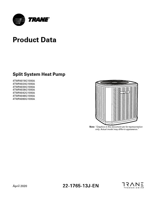
Product DataSplit System Heat Pump4TWR4018G1000A Array 4TWR4024G1000A4TWR4030G1000A4TWR4036G1000A4TWR4042G1000A4TWR4048G1000A4TWR4060G1000AN o t e:“Graphics in this document are for representationonly.Actual model may differ in appearance.”April202022-1765-13J-E NProduct Specifications(a)Certified in accordance with the Unitary Air-conditioner equipment certification program which is based on AHRI standard210/240.(b)Calculated in accordance with N.E.C.Only use HACR circuit breakers or fuses.(c)Reference the outdoor unit ship-with literature for refrigerant piping length and lift guidelines.Reference the refrigerant piping software pub#32-3312-xx or refrigerant piping application guide SS-APG006-xx for long line sets or specialty applications(xx denotes latest revision).(d)The outdoor condensing units are factory charged with the system charge required for the outdoor condensing unit,ten(10)feet of tested connecting line,and the smallest rated indoor evaporative coil match.Always verify proper system charge via subcooling(TXV/EEV)or superheat(fixed orifice)per the unit nameplate.(e)25,30,35and50foot linesets available.For a complete listing of lineset options available from equipment or supply stores,refer to the Trane Residentialand Light Commercial Product Handbook.P r o d u c t S p e c i f i c a t i o n s(a)Certified in accordance with the Unitary Air-conditioner equipment certification program which is based on AHRI standard210/240.(b)Calculated in accordance with N.E.C.Only use HACR circuit breakers or fuses.(c)Reference the outdoor unit ship-with literature for refrigerant piping length and lift guidelines.Reference the refrigerant piping software pub#32-3312-xx or refrigerant piping application guide SS-APG006-xx for long line sets or specialty applications(xx denotes latest revision).(d)The outdoor condensing units are factory charged with the system charge required for the outdoor condensing unit,ten(10)feet of tested connecting line,and the smallest rated indoor evaporative coil match.Always verify proper system charge via subcooling(TXV/EEV)or superheat(fixed orifice)per the unit nameplate.(e)25,30,35and50foot linesets available.For a complete listing of lineset options available from equipment or supply stores,refer to the Trane Residentialand Light Commercial Product Handbook.Accessory Description and UsageA n t i-S h o r t C y c l e T i m e r—Solid state timing device that prevents compressor recycling untilfive(5)minutes have elapsed after satisfying call or power e in area withquestionable power delivery,commercial applications,long lineset,etc.E v a p o r a t i o n D e f r o s t C o n t r o l—SPST Temperature actuated switch that cycles the condenseroff as indoor coil reaches freeze-up ed for low ambient cooling to30°F with TXV.R u b b e r I s o l a t o r s—Five(5)large rubber donuts to isolate condensing unit from transmittingenergy into mounting frame or e on any application where sound transmission needs tobe minimized.H a r d S t a r t K i t—Start capacitor and relay to assist compressor motor e in areas withmarginal power supply,on long linesets,low ambient conditions,etc.E x t r e m e C o n d i t i o n M o u n t K i t—Bracket kits to securely mount condensing unit to a frame orpad without removing any e in areas with high winds,or on commercial roof tops,etc.A H R I S t a n d a r d C a p a c i t y R a t i n g C o n d i t i o n sAHRI Standard210/240Rating Conditions1.Cooling80°F DB,67°F WB air entering indoor coil,95°F DB air entering outdoor coil.2.High Temperature Heating47°F DB,43°F WB air entering outdoor coil,70°F DB air enteringindoor coil.3.Low Temperature Heating17°F DB air entering indoor coil.4.Rated indoor airflow for heating is the same as for cooling.A H R I S t a n d a r d270R a t i n g C o n d i t i o n s—(Noise rating numbers are determiend with the unit incooling operations.)Standard Noise Rating number is at95°F outdoor air.Model NomenclatureOutdoor Units3 = 134 = 145 = 15Schematic DiagramsFigure 1. 1.5,2.0,2.5&3.5TonModelsFigure 2. 1.5,2.0,2.5&3.5TonModelsS c h e m a t i c D i a g r a m sFigure 3. 3.0TonS c h e m a t i c D i a g r a m sFigure 4.4and 5TonModelsS c h e m a t i c D i a g r a m sFigure 5.4and 5TonModelsS c h e m a t i c D i a g r a m sOutline DrawingMechanical Specification OptionsG e n e r a lThe outdoor condensing units are factory charged with the system charge required for theoutdoor condensing unit,ten(10)feet of tested connecting line,and the smallest rated indoorevaporative coil match.This unit is designed to operate at outdoor ambient temperatures as highas115°F.Cooling capacities are matched with a wide selection of air handlers and furnace coilsthat are AHRI certified.The unit is certified to UL1995.Exterior is designed for outdoorapplication.C a s i n gUnit casing is constructed of heavy gauge,galvanized steel and painted with a weather-resistantpowder paint finish.The corner panels are prepainted.All panels are subjected to our1,000hoursalt spray test.R e f r i g e r a n t C o n t r o l sRefrigeration system controls include condenser fan,compressor contactor and low and highpressure switches.A factory supplied,field installed liquid line drier is standard.C o m p r e s s o rThe compressor features internal over temperature and pressure protection.Other featuresinclude:Centrifugal oil pump and low vibration and noise.C o n d e n s e r C o i lThe outdoor coil provides low airflow resistance and efficient heat transfer.The coil is protectedon all four sides by louvered panels.L o w A m b i e n t C o o l i n gAs manufactured,this system has a cooling capacity to55°F.The addition of an evaporatordefrost control permits operation to40°F.The addition of an evaporator defrost control with TXVpermits low ambient cooling to30°F.The addition of the BAYLOAM107A low ambient kit permits ambient cooling to20°F.T h e r m o s t a t s—Cooling only and heat/cooling(manual and automatic change over).Sub-base tomatch thermostat and locking thermostat cover.22-1765-13J-EN11Trane-by Trane Technologies(NYSE:TT),a global innovator-creates comfortable,energy efficient indoor environments for commercial and residential applications.For more information,please visit or .The AHRI Certified mark indicates Trane U.S.Inc.participation in the AHRI Certification program.For verification of individual certified products,go to ahridirectory. org.Trane has a policy of continuous data improvement and it reserves the right to change design and specifications without notice.We are committed to using environmentally conscious print practices.22-1765-13J-EN28Apr2020Supersedes22-1765-13H-EN(October2019)©2020Trane。
第5讲-IPPBX,TG,IAD产品介绍
2
专业术语介绍
PBX:程控交换机 ,传统电话交换机,基于电路交换实现 电话功能。 IP PBX:IP PBX是一种基于IP的公司电话系统 TG:Trunk Gateway中继网关,负责对中继协议进行转换, 典型应用为将宽带协议转换为窄带协议(SIP/H323转换为 PRI/七号) AG: Access Gateway接入网关,负责将普通电话通过IP接 入到IP PBX上 IAD:综合接入设备,除具有AG功能外,一般还具有路由功 能,可以进行数据传输。
ATG产品主要用于建设IP接入网,采用V5接口与本地交换机(LE)连接,并通过 MGCP协议与VoIP网关连接。
16路E1接口(ATG2016) 2路FE接口 支持V5/MGCP协议 最大2000线用户容量 最大200路并发通话 最大128个VoIP网关 机框尺寸:442mm(宽)×67mm(高)×308mm(深) 交流输入:90V-260V, 50/60Hz
版权所有,禁止传播
19
AG产品-AG1016
AG1016是1U高19英寸VoIP接入网关设备,可直接应用于任何NGN/VoIP 网络中,负责将普通模拟电话通过IP网络接入到IPPBX上。接口类型为 DB100。
16路FXS 支持MGCP协议 支持设备堆叠功能 机框尺寸:428mm(宽)×44mm(高)×383mm(深) 交流输入:90V-260V 通过telnet和串口进行数据配置 详细配置见”AG IAD配置手册\AG1016“
版权所有,禁止传播
15
IPPBX设备-NC8000板位图
NC8000设备总共有11个槽位,分别为:0槽为NETS板,1~4槽为ET08板、AT0板 或ASU板,5槽现在为保留,6、7槽是cPCI板,8~11号槽是DSPA板,DSPA板扣 在NETS板内部。
12公斤重力发电led灯参数
LED灯作为一种节能环保的照明产品,受到了越来越多的关注和应用。
而12公斤重力发电LED灯作为一种新型的LED照明产品,其参数信息也备受关注。
本文将详细介绍12公斤重力发电LED灯的参数信息,以便读者更全面地了解这一产品。
一、产品型号:12公斤重力发电LED灯该LED灯的产品型号为12公斤重力发电LED灯,是一种利用重力发电原理来供电的LED照明产品。
二、功率与亮度1. 功率:12W该LED灯的功率为12W,属于较为节能的照明产品。
2. 亮度:800lm其亮度达到了800lm,能够提供良好的照明效果。
三、光色与色温1. 光色:白光该LED灯的光色为白光,适用于大部分室内环境的照明需求。
2. 色温:6000K色温为6000K,营造出明亮舒适的照明氛围。
四、光束角度光束角度:120°LED灯的光束角度为120°,能够有效扩散光线,提高照明覆盖范围。
五、使用寿命与保修1. 使用寿命:xxx小时该LED灯的使用寿命达到xxx小时,长时间稳定供电。
2. 保修信息:3年保修期在购物后的3年内,提供免费的维修与更换服务,保障产品的质量与使用体验。
六、其他参数1. 防护等级:IP65LED灯的防护等级为IP65,具有良好的防水防尘性能,适用于室内外各种环境。
2. 输入电压:AC 85-265VLED灯适用于广泛的输入电压范围,可在多种不同的电压环境下使用。
以上便是12公斤重力发电LED灯的各项参数信息,通过对这些参数的了解,读者可以更好地选择适合自己需求的LED照明产品。
希望本文对您有所帮助,谢谢!七、环保与节能12公斤重力发电LED灯作为一种利用重力发电原理来供电的照明产品,具有较高的能源利用率和环保性。
相比传统的光源,如白炽灯或荧光灯,LED灯具有更低的能耗和更长的使用寿命。
采用LED照明不仅能够减少能源的消耗,降低能源的浪费,还能够减少对环境的污染,降低碳排放。
LED灯的使用寿命长,减少了更换灯具的频率,减少了对资源的消耗,从而更好地保护了环境。
(最新)PD20G电动机保护器说明书(含漏电闭锁)
PD20G系列微机监控电机保护装置使用手册USER’S MANUAL江阴东瑞电力仪表有限公司地址:江阴市澄山路188号邮编:214432电话:0510-******** 86276870传真:*************E-mail:*****************.cnhttp:// 1.概述PD20G系列微机监控电机保护器适用于AC380V、AC660V低压系统,作为低压异步电动机和增安型电动机的保护、监测和控制的新一代智能化综合装置。
有先进的电动机保护、监控功能,同时显示各项整定参数信息,并且采用现场总线,为现代化的设备管理带来很大的便利。
符合标准:GB3836.3-2000、GB14048.4-2003、IEC2552.特点●交流采样,测量A、B、C三相电流及控制回路电压●现场显示电动机运行状态,保存三次电动机故障跳闸记录●一路保护输出,一路可编程继电器输出●高亮LED显示,跟随电动机运行状态和用户要求实时显示●三相电流不平衡、断相、欠流、自启动等功能用户可取可舍●当电动机过流时过流灯(设置灯)闪烁告警,过流倍数越大,闪烁越快●故障定位明确,显示故障时的电压值或电流值,断相显示哪一相,电流不平衡显示大小两相●采用RS485通信总线,可广泛用于各种监控系统作为带有电机保护及控制的智能化监控单元(选择配置)●一路4-~20mA模拟量电流输出任意选择对应A、B、C三相电流之一(选择配置)●漏电保护、漏电闭锁等功能用户可根据需要增选配置3.主要功能保护功能:过流、欠流、堵转、断相、三相电流不平衡、短路、漏电(选配)等故障保护测量功能:三相电流、漏电电流和对地绝缘电阻的测量和显示通用功能:增安型电动机保护、三相异步电动机保护、馈线保护,三种保护装置通用通信功能:通过本保护器的RS485接口与上层系统通信。
总线接口支持参数设置、控制及监测等功能。
通信协议遵循Modbus-RTU标准。
一般采用RS485总线接口进行物理连接,通常上位机或PLC设备作为主站,本保护器作为子站。
迪文科技ADA360K120S001A产品数据手册说明书
ADA360K120S001A产品特点:●宽输入电压:输入工作电压范围100-240VAC。
●低功耗:空载损耗<0.075W。
●高能效:六级能耗,功率效率89%。
●高可靠性:符合EN60601-1 CLASS Ⅱ安全等级和 2×MOPP 绝缘防护等级 , 通过 CE 认证。
●阻燃绝缘:UL94V-0 阻燃耐热材料。
●保护种类:短路保护、过流保护、过压保护,并可自恢复。
●便捷转换:适配英规、澳规、欧规、美规、中规五款转换插头。
Features:●Wide input voltage: the input working voltage range is 100-240VAC.●Low power consumption: No-load <0.075W.●High Energy Efficiency: Six levels of energy consumption, power efficiency up to 89%.●High reliability: Comply with EN60601-1 CLASS Ⅱ safety level and 2×MOPP insulation protection level, and pass CE.●Flame retardant insulation:UL94V-0 flame retardant heat resistant material.●Protection types:short circuit protection, over current protection, over voltage protection, and self-recovery.●Convenient conversion: Adapt to five conversion plugs of British, Australian, European, American, and Chinese.1、产品介绍Product IntroductionADA360K120S001A 产品是一款单组输出的壁挂式电源适配器。
- 1、下载文档前请自行甄别文档内容的完整性,平台不提供额外的编辑、内容补充、找答案等附加服务。
- 2、"仅部分预览"的文档,不可在线预览部分如存在完整性等问题,可反馈申请退款(可完整预览的文档不适用该条件!)。
- 3、如文档侵犯您的权益,请联系客服反馈,我们会尽快为您处理(人工客服工作时间:9:00-18:30)。
产品规格书
产品名称: 120W方形投光灯
产品型号: XR-TGD120W
文件编号: TGD-007
文件版次: A/1
制订部门:技术部
文件发放部门:技术部、生产部、品管部、国内营销部、国际贸易部、工业工程部制订:审核:批准:
●宽范围工作电压,长寿命,低光衰,维护成本低。
●光效高,节能省电,比传统节能灯省电75%以上。
●可直接替换传统大功率钠灯。
●环保无污染,不含对环境有害的汞污染。
二. 外观尺寸:
四、光通量测试图:
六、平均照度图:
七、包装方式:
八、应用范围:
户外照明
九、安装说明
1、配置必须由专业人员安装。
2、接线时必须切断外部电源。
3、接线时外部电源线的线芯不得外露。
注意:所有信息如有改动恕不另作通知。
如有疑问,请联系供货商。
十、LED铭牌:
备注:产品铭牌中的颜色根据订单规定打勾。