SGM48752 CMOS模拟多路复用器
艾尔文迪电子UHF-5805四通道可重复充电无线麦克风系统说明书
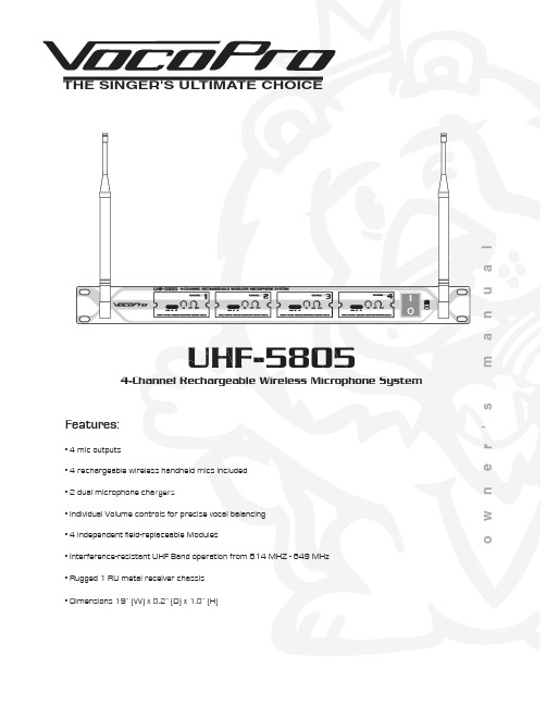
la u n a ms 'r e n w o THE SINGER'S ULTIMATE CHOICEUHF-5805Features:• 4 mic outputs• 4 rechargeable wireless handheld mics included • 2 dual microphone chargers• Individual Volume controls for precise vocal bala • Individual Volume controls for precise vocal balancing • 4 independent field-replaceable Modules• Rugged 1 RU metal receiver chassis • Dimensions 19” (W) x 8.2” (D) x 1.8” (H)4-Channel Rechargeable Wireless Microphone System• Interference-resistant UHF Band operation from 614 MHZ - 649 MHzTable of contentsSafety instructions (2)FCC information (3)Welcome (4)Listening for a lifetime (5)Specifications (6)Microphone basics (7)Before getting started (8)Mounting (9)Getting connected (10)Maintenance procedures (11)Charging the Microphones (12)Front and rear panel descriptions and functions (13)UHF-5805 & stage monitor/P.A. loudspeakers (14)Operations (14)Troubleshooting (15)��������������������CAUTION: To reduce the risk of electric shock, do not remove cover (or back). Nouser-serviceable parts inside. Only refer servicing to qualified service personnel.�������To reduce the risk of fire or electric shock, do not expose this unit to rain or moisture.��������������������������������The lightning flash & arrowheadsymbol, within an equilateral triangle, is intended to alert you to the presence of danger.The exclamation point within anequilateral triangle is intended to alert you to the presence of importantoperating and servicing instructions.�������������������� - All the safety and operating instructions should be read before the appliance is operated.���������������������� - The safety and operating instructions should be retained for future reference.���������������� - All warnings on the appliance and in the operating instructions should be adhered to.���������������������� - All operating and use instructions should be followed.�������������� - Do not use attachments notrecommended by the product manufacturer as they may cause hazards.��������������������� - Do not use this unit near water. For example, near a bathtub or in a wet basement and the like.������������������� - The appliance should be used only with a cart or stand that is recommended by the manufacturer.���� An appliance and cart combination should be moved with care. Quick stops, excessive force, and uneven surfaces may cause an overturn.�������������� - The appliance should be situated so its location does not interfere with its proper ventilation. For example, the appliance should not be situated on a bed, sofa, rug, or similar surface that may block the ventilation slots.������� - The appliance should be situated away from heat sources such as radiators, heat registers, stoves, or other appliances (including amplifiers) that produce heat.����������������� - The appliance should beconnected to a power supply only of the type described in the operating instructions or as marked on the appliance.����������������������������� - Precautions should be taken so that the grounding or polarization means of an appliance is not defeated.������������������������� - Power-supply cordsshould be routed so that they are not likely to be walked on or pinched by items placed upon or against them, paying particular attention to cords at plugs,convenience receptacles, and the point where they exit from the appliance.������������ - Unplug this unit from the wall outlet before cleaning. Do not use liquid cleaners or aerosol cleaners. Use a damp cloth for cleaning.��������������� - An outdoor antenna should be located away from power lines.������������������ - The power cord of the appliance should be unplugged from the outlet when left unused for a long period of time.��������������������������� - Care should be taken so that objects do not fall and liquids are not spilled into the enclosure through openings.���������������������������� - The appliance should be serviced by qualified service personnel when:A. The power supply cord or plug has been damaged; or B. Objects have fallen into the appliance; or C. The appliance has been exposed to rain; orD. The appliance does not appear to operate normally or exhibits a marked change in performance; orE. The appliance has been dropped, or the enclosure damaged.������������� - The user should not attempt to service the appliance beyond that described in the operating instructions. All other servicing should be referred to qualified service personnel.������To CATV system installer's (U.S.A.): This reminder is provided to call the CATV system installer's attention to Article 820-40 of the NEC that provides guidelines for proper grounding and, in particular, specifies that the cable ground shall be connected as close to the point of cable entry as practical.SAFETY INSTRUCTIONS1. IMPORTANT NOTICE: DO NOT MODIFY THIS UNIT!: This product, when installed as indicated in the instructions contained in this manual, meets FCCrequirements. Modifications not expressly approved by Vocopro may void your authority, granted by the FCC, to use this product.2. IMPORTANT: When connecting this product to accessories and/or another product use only high quality shielded cables. Cable(s) supplied with this product MUST be used. Follow all installation instructions. Failure to follow instructions could void your FCC authorization to use this product in the U.S.A.3. NOTE: This product has been tested and found to comply with the requirements listed in FCC Regulations, Part 15 for Class "B" digital devices. Compliance with these requirements provides a reasonable level of assurances that your use of this product in a residential environment will not result in harmful interference with other electronic devices. This equipment generates/uses radio frequencies and, if not installed and used according to the instructions found in the owner's manual, may cause interference harmful to the operation of other electronic devices. Compliance with FCC regulations does not guarantee that interference will not occur in all installations. If this product is found to be the source of interference, which can be determined by turning the unit "Off" and "On", please try to eliminate the problem by using one of the following measures:Relocate either this product or the device that is being affected by the interference.Use power outlets that are on different branch (circuit breaker or fuse) circuits or install AC line filter(s).In the case of radio or TV interference,relocate/reorient the antenna. If the antenna lead-in is 300-ohm ribbon lead, change the lead-in to coaxial type cable.If these corrective measures do not produce satisfactory results, please contact your local retailer authorized to distribute Vocopro products. If you can not locate the appropriate retailer, please contact Vocopro, 1728 Curtiss Court, La Verne, CA 91750.1. To ensure the finest performance, please read this manual carefully. Keep it in a safe place for future reference.2. Install your unit in a cool, dry, clean place - away from windows, heat sources, and too much vibration, dust, moisture or cold. Avoid sources of hum (transformers, v motors). To prevent fire or electrical shock, do not expose to rain and water.3. Do not operate the unit upside-down.4. Never open the cabinet. If a foreign object drops into the set, contact your dealer.5. Place the unit in a location with adequate air circulation. Do not interfere with its proper ventilation; this will cause the internal temperature to rise and may result in a failure.6. Do not use force on switches, knobs or cords. When moving the unit, first turn the unit off. Then gently disconnect the power plug and the cords connecting to other equipment. Never pull the cord itself.7. Do not attempt to clean the unit with chemical solvents: this might damage the finish. Use a clean, dry cloth.8. Be sure to read the "Troubleshooting" section on common operating errors before concluding that your unit is faulty.9. This unit consumes a fair amount of power even when the power switch is turned off. We recommend that you unplug the power cord from the wall outlet if the unit is not going to be used for a long time. This will save electricity and help prevent fire hazards. To disconnect the cord, pull it out by grasping the plug. Never pull the cord itself.10. To prevent lightning damage, pull out the power cord and remove the antenna cable during an electrical storm. 11. The general digital signals may interfere with other equipment such as tuners or receivers. Move the system farther away from such equipment if interference is observed.NOTE:Please check the copyright laws in your country beforerecording from records, compact discs, radio, etc.Recording of copyrighted material may infringecopyright laws.CAUTIONThe apparatus is not disconnected from the AC power source so long as it is connected to the wall outlet, even if the apparatus itself is turned off. To fully insure that the apparatus is indeed fully void if residual power, leave unit disconnected from the AC outlet for at least fifteen seconds. ����������������������������������������������������������������������������������Be sure to position the voltage selector to match the voltage of your local power lines before installing the unit.240V120VFCC INFORMATION (U.S.A.)Welcome...And Thank you for purchasing the UHF-5805from VocoPro, your ultimate choice in Karaoke entertainment! With years of experience in the music entertainment business, VocoPro is a leading manufacturer of Karaoke equipment, and has been providing patrons of bars, churches, schools, clubs and individual consumers the opportunity to sound like a star with full-scale club models, in-home systems and mobile units. All our products offer solid performance and sound reliability, and to reinforce our commitment to customer satisfaction, we have customer service and technical support professionals ready to assist you with your needs. We have provided some contact information for you below.VocoPro1728 Curtiss CourtLa Verne, CA 91750Toll Free: 800-678-5348TEL: 909-593-8893FAX: 909-593-8890VocoPro Company Email DirectoryCustomer Service & General Information****************Tech Support***********************Remember Our WebsiteBe sure to visit the VocoPro website for the latest information on new products, packages and promos. And while you're there don't forget to check out our Club VocoPro for Karaoke news and events, chat rooms, club directories and evena KJ Service directory!We look forward to hearing you sound like a PRO, with VocoPro, your ultimate choice in Karaoke entertainment.FOR YOUR RECORDSPlease record the model number and serial number below, for easy reference, in case of loss or theft. These numbers are located on the rear panel of the unit. Space is also provided for other relevant informationModel NumberSerial NumberDate of PurchasePlace of PurchaseSelecting fine audio equipment such as the unit you’ve just purchased is only the start of your musical enjoyment. Now it’s time to consider how you can maximize the fun and excitement your equipment offers. VocoPro and the Electronic Industries Association’s Consumer Electronics Group want you to get the most out of your equipment by playing it at a safe level. One that lets the sound come through loud and clear without annoying blaring or distortion and, most importantly, without affecting your sensitive hearing.Sound can be deceiving. Over time your hearing “comfort level” adapts to a higher volume of sound. So what sounds “normal” can actually be loud and harmful to your hearing. Guard against this by setting your equipment at a safe level BEFORE your hearing adapts.To establish a safe level:• Start your volume control at a low setting.• Slowly increase the sound until you can hear it comfortably and clearly, and withoutdistortion.Once you have established a comfortable sound level:• Set the dial and leave it there.• Pay attention to the different levels in various recordings.Taking a minute to do this now will help to prevent hearing damage or loss in the future. After all, we want you listening for a lifetime.Used wisely, your new sound equipment will provide a lifetime of fun and enjoyment. Since hearing damage from loud noise is often undetectable until it is too late, this manufacturer and the Electronic Industries Association’s Consumer Electronics Group recommend you avoid prolonged exposure to excessive noise. This list of sound levels is included for your protection.���������������������������Level������������ExampleQuiet library, Soft whispersLiving room, Refrigerator, Bedroom away from traffic Light traffic, Normal ConversationAir Conditioner at 20 ft., Sewing machineVacuum cleaner, Hair dryer, Noisy RestaurantAverage city traffic, Garbage disposals, Alarm clock at 2 ft.��������������������������������������������������������������Level��������������ExampleSubway, Motorcycle, Truck traffic, Lawn MowerGarbage truck, Chainsaw, Pneumatics drillRock band concert in front of speakersGunshot blast, Jet planeRocket launching pad-Information courtesy of the Deafness Research FoundationListening For A LifetimeSpecifi cationsReceiverCarrier Frequency Range: UHF 614~694MHzOscillation Mode: Quartz Controlled Fixed Frequency Stability: 10 PPMSensitivity: 1.6uV @ sinad =12dBMax. Deviation Range: 50HzS/N Ratio:>105dBT.H.D.: <0.5% @ 1kHzImage rejection: 85dB typicalSpurious Rejection: 75dB typicalFrequency Response: 40Hz~16kHzSquelch Control: dual-squelch circuitMax. Output Level: Balance: 0~400mV, Unbalance: 0~200mV Power Supply: External DC Power Supply, 0.7A, 12~15V DC Dimensions: 19”(L) x 8.2”(D) x 1.8”(H)Microphone basicsMicrophone PositionThe UHF-5805 is ideal for close-up vocals and can be held in the hand or mounted on a mic stand. The most common applications and placement techniques are listed below. Keep in mind that microphone technique is largely a matter of personal taste, and there is no one “correct” microphone position.Proximity EffectWhen the sound source is less than ¼ in. from the microphone, the microphone boosts bass frequencies (by 6 to 10 dB at 100 Hz), creating a warmer and richer bass sound than when farther away. This effect, known as proximity effect, happens only in unidirectional dynamic microphones like the UHF-5805.FeedbackFeedback occurs when the amplified sound from any loudspeaker reenters the sound system through any open microphone and is repeatedly amplified. Most commonly, feedback is caused by the following condi-tions: placing loudspeakers too close to microphones, having too many open active microphones, boosting tone controls indiscriminately (mainly treble) and performing in areas with high ratios of room surfaces that have hard and reflective surfaces such as glass, marble and wood. What to do if feedback occurs before the sound system is loud enough?• Request that the talker speak louder into the microphone.• Reduce the distance from the talker to the microphone. Each time this distance ishalved, the sound system output will increase by 6dB.• Reduce the number of open microphones.• Move the loudspeaker farther away from the microphone. Each time this distance isdoubled, the sound system output can be increased by 6dB.• Move the loudspeaker closer to the listener.• Use an equalizer/feedback reducer to cut the frequency bands in which the feedbackoccurs.Microphone Placement & Tone QualityLead & Backup VocalsLips should be less than 3” from or even touching the windscreen on an axis to the microphone. Doing this creates a robust sound, emphasizes bass and provides maximum isolation from other sources.SpeechWhen giving a speech or simply speaking, place the microphone 4” to 10” away from the mouth, just above nose height for a natural sound with reduced bass. You can also place the microphone 8” to 16” away from the mouth, slightly off to one side, for a more “distant” sound with highly reduced bass and minimal “s” sounds.Before getting startedBefore starting any installation procedures, it is recommend to completely unpack all the package contents. The original packaging should be kept in the event that re-shipping is needed. Upon unpacking the UHF-5805, you should have received the following items:•Custom Aluminum Travel Case (1)• UHF-5805 Receiver (1)• Handheld Microphones (4)• 3 ft. male/male ¼” cable (1)• 14V DC Main Unit power adapter (1), 9V DC Charger power adapter (2)• Dual Microphone Charger (2)9V9VUniversal Mic Charger Universal Mic Charger14VTo install the UHF-5805 to a 19” rack case, complete the steps below.1. Attach mounting brackets to the UHF-5805 via the supplied mounting screws.2. Align the UHF-5805 with the desired space in rack and slowly slide in, rear panel first.3. While aligned, use rack case screws (not included) in the order shown below to stabilize the UHF-5805 in its space, using the “X” rotation (numbered below) will ensure even tension and flush alignment.MountingNOTE: Depending on your rack case design, it may be neces-sary to allow for sufficient space for the antennas.NOTE: Do not tighten screws firmly until all screws are in place.����Maintenance proceduresRemoving the Field Replaceable ModulesEach of the 4 microphone modules on the UHF-5805 were designed in a way that allows them to slide out. This is a convenient feature if ever a module needs to be repaired or replaced.1. Remove the two screws that fasten the module to the front panel.2. To remove the module, simply slide the module out of the compartmentNOTE: It might be helpful to use a flat-head screwdriver to nudge the module out of its compartment.3. To re-insert, slide the module into compartment until it is completely secured. Secure the module withthe screws.The UHF-5805 comes with two dual chargers that let you charge all four microphones at the same time.Charging the MicrophonesIf the LED light on the microphone(s) does not light up when the microphone is turned on, this indicates that the microphone needs to be chargedTo charge:1. Place the microphone in the charger slot, the LED on the charger will be lit while the microphone is charging.2. When the LED on the charger turns off, the microphone is charged and can be removed.NOTE: For longest battery life, be sure to turn the microphones off when not in use.Reading the LED IndicatorsThe LEDs on the charger indicate the charging status. There are three states: blinking, on, and off.• Blinking - The power is connected to the charger but there are no microphones being charged • On - The microphone is being charged• Off - The microphone is completely charged and can be removed.Charger and Microphone Descriptions and Functions1. Microphone slots - Insert ne slots the microphones in these slots to charge2. Bodypack charger2. Body - pack charger Insert the optional rechargeable body pack in this slot to charge3. Microphone charge LED charge LED charge LE D in D - Indicate the - I indicators charging status of the microphones4. Bodypack charge LED in 4. Body - Indicates the charging status of the bodypack- I dicator - The color of this LED indicates the microphone’s charge level. Green means 5. Charge Indicator LED the charge is high, Orange means the charge is getting low and should be charged, and Red means the charge is very low and must be charged immediately.- Used to turn the microphone power ON and OFF . The mic power is ON when the 6. Power Switch switch is in the ON position and the power is OFF when the switch is in the OFF position.Charging the MicrophonesUniversal Mic Charger11562334NOTE:Make sure you are using the 9V power adapter for microphone chargersFront and rear panel descriptions and functions1.ANTEN ANTE NNA N - P NAS rovide both RF and AF signals.- Indicates whether the UHF-5805 is ON or OFF . When it is lit, the power is ON.2. POWER (LED) - Lights when RF signals are received from the microphone channels. - L 3. RF (LED) - 4. AF (LED)Lights when AF signals are received from the microphone channels.5. SQUELCH controls SQUELCH - Manual controls for controlling each microphone’s signal strength for bestcontrols performance. Turn clockwise to increase SQUELCH control and turn counter-clockwise to decreaseSQUELCH application.- Adjusts the individual VOLUME of the receiver’s 4 microphone channels.6. VOLUME controls - Contains the SQUELCH and VOLUME controls for each of the 4 wireless 7. MICROPHONE modules - C microphones. Each module can be easily removed individually. - Turns the UHF-5805 ON/OFF .8. POWER button - Main power jack for connection to an AC electrical outlet or power strip/surge 9. AC POWER connection - M protector. NOTE: Make sure you are connecting the 14V power adapter here.- This ¼” unbalanced output jack is for output connection to amplifiers, effects devices 10. MIXED OUTPUT or mixers. Both mic channels are output through this jack for mixed output. - These XLR unbalanced output jacks are for output connections to amplifiers, effects 11. XLR AUDIO OUTS devices or mixers. These are for separate mic channel connections with unmixed mic output.1567910113428UHF-5805 & stage monitor/p.a. loudspeakersIf you will be using the UHF-5805 with stage monitors and/or P.A. system, try the following:• Place the stage monitor directly behind the microphone.• Locate the P.A. loudspeakers so that they point away from the rear of the microphone. (With the speakers located in these positions, the possibility of feedback is greatly reduced).• Always check the stage setup before a performance to ensure optimum placement of microphone and monitors.IMPORTANT: Every wireless microphone installation is a unique situation, and can present a variety of prob-lems. Never attempt a live performance without first conducting a “walkthrough” test of the system in the performing area. If major changes (additional wireless systems or intercoms, relocation of scenery, etc.) have been made since the last walk-through test, check the wireless system again, as close to performance time as possible.P.A. Speakers Facing AwayFrom Rear of MicrophoneMonitor Directly BehindMicrophoneOperations2. Adjust the receiver’s VOLUME controls to approximately 50%.3. Switch the microphone’s POWER BUTTONS to the ON positions.4. Talk or sing into the microphones. During normal operation, the RF/AF signal LED’s will light when amicrophone is being used.5. Adjust the receiver’s VOLUME controls until the output levels are balanced w ith each other and otherpossible source output i.e. CD+G tracks.TroubleshootingProblemsNo sound output, RF/AF LED(s) are not glowingReceived signal is noisy or contains extraneous sounds with the microphone(s) ON.There is noise coming from the receiver with the microphones turned OFF.Momentary loss of sound as microphone(s) are moved throughout the operating range.Solutions• Make sure the microphone and receiver power switches and receiver are set to the ON position.• Check microphone charge to ensure there is sufficient power. Charge mic if necessary• Check receiver’s AC power connection.• Make sure antennas are firmly connected and extended to an optimal position.• If necessary, reduce the distance between the microphones and receiver.• Turn up the receiver’s VOLUME level controls.• Check for proper connection between receiver and external amplifier/mixer.• Talk into the microphone and observe the receiver’s RF/AF signal LED’s. If they glow, the problem is elsewhere in the sound system.• Check microphone(s) charge and recharge if the charge is low.• Remove local sources of UHF interference, such as lighting equipment.• Adjust the squelch controls on the front of the UHF-5805 receiver.• Signal may be too weak. If so, reposition antennas. (If possible, move them closer to the transmitter).• Remove local sources of UHF interference, such as lighting equipment.• Reposition the receiver or antennas.• Reposition the receiver, perform a “walkthrough”, and observe the signal strengths. If audio dropouts persist, mark these “dead spots” in the operating area and avoid them during the performance.UHF-5805 Manual © VocoPro 2011V 1.1Erratic LED blinking on the main receiver modules• Make sure the 14V power adapter is pluggedin to the main unit. Do not use the 9V adapterswith the main receiver unit.• If the power adapter is the 14V and the main unitlights are still blinking, contact VocoPro for areplacement。
双通道低成本模数转换器cs5550中文
4 寄存器描述…………………………………………………………………………..…………………..18 4.1 配置寄存器………………………………………………………………………………...18 4.2 DC偏移寄存器…………………………………………………………………………...19 4.3 AC/DC增益寄存器……………………………………………………………………..19 4.4 周期计数寄存器…………………………………………………………………………...19 4.5 输出寄存器………………………………………………………………………………...20 4.6 滤波输出寄存器…………………………………………………………………………...20 4.7 状态寄存器和屏蔽寄存器………………………………………………………………...20 4.8 AC偏移寄存器…………………………………………………………………………...21 4.9 温度传感器数据输出寄存器………………………...……………………………………21 4.10 控制寄存器………………………………………………………………………………...21
4 of 22
8/11/03
1. 特性与规格说明 . 最大值和最小值参数是指在所有的操作条件可被保证的值.
. 典型参数是在标准供电和25°C时的测量值. . DGND = 0V.所有电压是指对 0V 的电压值.
模拟特性
参数
符号 最小值
精度(两个通道)
共模抑制比
CMRR
80
偏移漂移
-
模拟输入(AIN1±) 差分输入范围 {(AIN1+) - (AIN1- )}
测量和参考输入
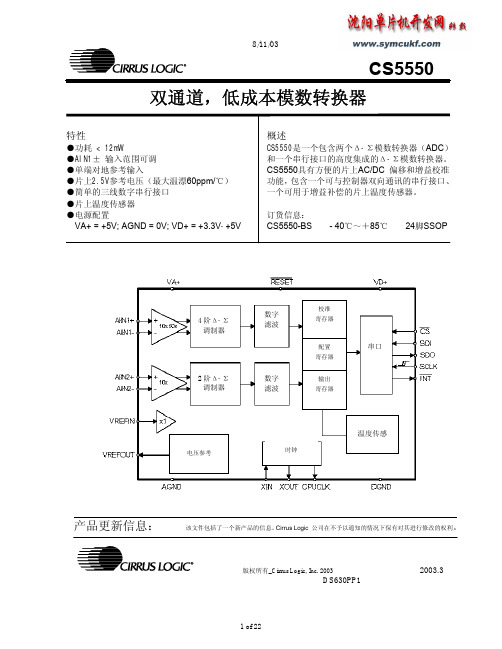
差分模拟输入9,10,15,16 AIN1+, AIN1-, AIN2+, AIN2- —差分模拟输入引脚。
Xilinx-v5
- 对于真双端口运行,每端口宽度可达 36 位宽 - 对于简单双端口运行 (一个读端口和一个写端口),
每端口宽度可达 72 位宽 - 9 位、18 位、36 位和 72 位宽度的存储器位数及奇偶
校验 / 边带存储器支持 - 从 32K x 1 到 512 x 72 的配置(8K x 4 到 512 x 72 用
于 FIFO 运行) • 多采样率 FIFO 支持逻辑
- 具有完全可编程近满标志和近空标志的满标志和空标 志
• 同步 FIFO 支持,没有标志不确定的问题 • 用于提高性能的可选流水线级数 • 字节写功能 • 专用级联布线,无需 FPGA 布线即可形成 64K x 1 存储
- 符合 PCI Express 基础规范 (PCI Express Base Specification) 1.1
- 每模块支持 1 倍、2 倍、4 倍或 8 倍通道宽度 - 与 RocketIO™ 收发器配合使用 • 三态 10/100/1000 Mb/s 以太网 MAC
(LXT/SXT)
- 可以将 RocketIO 收发器用作 PHY,也可以用多种软 MII (媒体独立接口)方案将其连接到外部 PHY
器 • 满足高可靠性存储器要求的集成可选 ECC • 针对 18 Kb (及以下)运行的特殊降功耗设计
550 MHz DSP48E Slice
• 25 x 18 补数乘法运算 • 用于增强性能的可选流水线级数 • 用于乘法累加 (MACC) 运算的可选 48 位累加器,可选
择将累加器级联为 96 位 • 用于复数乘法运算或乘加运算的集成加法器 • 可选按位逻辑运行模式 • 每 Slice 独立 C 寄存器 • 在一个 DSP 列中完全可级联,无需外部布线资源
PWM控制芯片SG3525原理及应用
PWM控制芯片SG3525原理及应用SG3525是一款经典的PWM控制芯片,具有广泛的应用领域。
本文将从原理和应用两个方面进行探讨,详细介绍SG3525的工作原理及在各个领域中的应用。
一、SG3525的工作原理SG3525是一款双路可调节PWM控制器芯片,由一对对称反馈比较器、三角波发生器、误差放大器、电压调节电路、电平移位电路和PWM输出级组成。
其工作原理如下:1.错误放大器:SG3525通过与输入信号进行比较,产生误差放大器输出的控制信号,以实现对输出波形的控制。
2.三角波发生器:通过内部电容和电阻的组合,生成一定幅值和频率的三角波信号,用于与错误放大器输出信号进行比较。
3.反馈比较器:SG3525具有一对对称的反馈比较器,将错误放大器输出信号与三角波信号进行比较,产生相应的控制信号。
4.电平移位电路:对反馈比较器的控制信号进行电平移位处理,以适应各种应用场景的控制要求。
5.PWM输出级:将经过电平移位的控制信号,经过输出级放大、滤波处理后,形成PWM信号。
二、SG3525的应用领域SG3525因其可靠性、稳定性以及功能强大而在电子领域应用广泛,以下是常见的应用领域及应用案例:1.开关电源:SG3525可以广泛应用于开关电源中,通过控制MOSFET等开关管的导通时间,实现对开关电源输出电压的稳定控制。
例如,SG3525可以用于UPS(不间断电源)的开关电源控制电路。
2.电动机驱动系统:SG3525可以用于电动机的速度和方向控制,通过控制PWM输出信号的占空比,实现电动机的转速和转向的控制。
例如,SG3525可以实现永磁直流电机的调速。
3.照明控制:SG3525可用于照明领域中的调光控制,通过控制PWM输出信号的占空比,实现对LED灯或者灯泡等照明设备的亮度调节。
4.变频调速系统:SG3525可以应用于交流电机的变频调速系统中,通过控制PWM输出信号的频率和占空比,实现对交流电机转速的精确控制。
SGM8052中文资料

SGM8051/2/4 SGM8053/5250MHz, Rail-to-Rail Output CMOS Operational AmplifierSG Microelectronics Co, LtdELECTRICAL CHARACTERISTICS : V S = +5V (G=+2, R F =887Ω, R L = 150Ω, unless otherwise noted)Specifications subject to change without notice.PACKAGE/ORDERING INFORMATIONMODEL CHANNEL ORDER NUMBER PACKAGEDESCRIPTIONPACKAGE OPTION MARKING INFORMATIONSGM8051XN5/TR SOT23-5 Tape and Reel, 3000 8051 SGM8051 SingleSGM8051XS/TRSO-8 Tape and Reel, 2500 SGM8051XS SGM8052XMS/TRMSOP-8 Tape and Reel, 3000 SGM8052XMS SGM8052 DualSGM8052XS/TR SO-8 Tape and Reel, 2500 SGM8052XSSGM8053XN6/TRSOT23-6Tape and Reel, 30008053SGM8053Single with shutdownSGM8053XS/TR SO-8 Tape and Reel, 2500 SGM8053XS SGM8054XS14 SO-14 Tube, 50 SGM8054XS14 SGM8054XTS14 TSSOP-14 Tape and Reel, 3000 SGM8054XTS14 SGM8054XS/TR SO-16 Tape and Reel, 2500 SGM8054XS SGM8054 QuadSGM8054XTSTSSOP-16 Tape and Reel, 3000 SGM8054XTS SGM8055 Dualwith shutdownSGM8055XMS/TRMSOP-10Tape and Reel, 3000SGM8055XMSABSOLUTE MAXIMUM RATINGSSupply Voltage, V+ to V- ......................................... 7.5 V Common-Mode Input Voltage........................................ (–V S )– 0.5 V to (+V S ) +0.5V Storage Temperature Range ................ –65℃ to +150℃ JunctionTemperature ..............................................................160℃ Operating Temperature Range ........... –55℃ to +150℃ Package Thermal Resistance @ T A = 25℃SOT23-5, θJA ......................................................... 190/W ℃ SOT23-6, θJA ......................................................... 190/W ℃ SO-8, θJA ..................................................................125/W ℃MSOP-8, θJA .......................................................... 216/W ℃ MSOP-10, θJA ........................................................ 216/W ℃ SO-16, θJA ................................................................ 82/W ℃ TSSOP-16, θJA ....................................................... 105/W ℃ Lead Temperature Range (Soldering 10 sec)......................................... 260℃ESD SusceptibilityHBM...........................................................................1000V MM. (400V)NOTES1. Stresses above those listed under Absolute Maximum Ratings may cause permanent damage to the device. This is a stressrating only; functional operation of the device at these or any other conditions above those indicated in the operational section of this specification is not implied. Exposure to absolute maximum rating conditions for extended periods may affect device reliability.CAUTIONThis integrated circuit can be damaged by ESD. Shengbang Micro-electronics recommends that all integrated circuits be handled with appropriate precautions. Failure to observe proper handling and installation procedures can cause damage.ESD damage can range from subtle performance degradation to complete device failure. Precision integrated circuits may be more susceptible to damage because very small parametric changes could cause the device not to meet its published specifications.TYPICAL PERFORMANCE CHARACTERISTICSAt T A= +25℃, V S = +5V, G = +2, R F= 887Ω, R G = 887Ω, and R L = 150Ωconnected to Vs/2,unless otherwise noted.TYPICAL PERFORMANCE CHARACTERISTICSAt T A = +25℃, V S = +5V , G = +2, R F= 887Ω, R G = 887Ω, and R L = 150Ω connected to Vs/2,unless otherwise noted.Non-Inverting Small Signal Step Response Non-Inverting Large Signal Step ResponseTime(50ns/div) Time(50ns/div)O u t p u t V o l t a g e (50m V /d i v )O u t p u t V o l t a g e (500m V /d i v )Rail-To-RailG = +2 R F = 887ΩR L = 1K Ω4.88V0VTime(200ns/div)TYPICAL PERFORMANCE CHARACTERISTICSAt T A= +25℃, V S = +5V, G = +2, R F= 887Ω, R G = 887Ω, and R L = 150Ωconnected to Vs/2,unless otherwise noted.TYPICAL PERFORMANCE CHARACTERISTICSAt T A= +25℃, V S = +5V, G = +2, R F= 887Ω, R G = 887Ω, and R L = 150Ωconnected to Vs/2,unless otherwise noted.TYPICAL PERFORMANCE CHARACTERISTICSAt T A= +25℃, V S = +5V, G = +2, R F= 887Ω, R G = 887Ω, and R L = 150Ωconnected to Vs/2,unless otherwise noted.APPLICATION NOTESDriving Capacitive LoadsThe SGM805x family is optimized for bandwidth and speed, not for driving capacitive loads. Output capacitance will create a pole in the amplifier’s feedback path, leading to excessive peaking and potential oscillation. If dealing with load capacitance is a requirement of the application, the two strategies to consider are (1) using a small resistor in series with the amplifier’s output and the load capacitance and (2) reducing the bandwidth of the amplifier’s feedback loop by increasing the overall noise gain.Figure 1 shows a unity gain follower using the series resistor strategy. The resistor isolates the output from the capacitance and, more importantly, creates a zero in the feedback path that compensates for the pole created by the output capacitance.V IN V OUTFigure 1. Series Resistor Isolating Capacitive LoadPower-Supply Bypassing and Layout The SGM805x family operates from either a single +2.7V to +5.5V supply or dual ±1.35V to ±2.75V supplies. For single-supply operation, bypass the power supply V DD with a 0.1µF ceramic capacitor which should be placed close to the V DD pin. For dual-supply operation, both the V DD and the V SS supplies should be bypassed to ground with separate 0.1µF ceramic capacitors. 2.2µF tantalum capacitor can be added for better performance.Good PC board layout techniques optimize performance by decreasing the amount of stray capacitance at the op amp’s inputs and output. To decrease stray capacitance, minimize trace lengths and widths by placing external components as close to the device as possible. Use surface-mount components whenever possible.For the high speed operational amplifier, soldering the part to the board directly is strongly recommended. Try to keep the high frequency big current loop area small to minimize the EMI (electromagnetic interfacing).V SSVnVpV SS(GND)Figure 2. Amplifier with Bypass Capacitors GroundingA ground plane layer is important for high speed circuit design. The length of the current path speed currents in an inductive ground return will create an unwanted voltage noise. Broad ground plane areas will reduce the parasitic inductance.Input-to-Output CouplingTo minimize capacitive coupling, the input and output signal traces should not be parallel. This helps reduce unwanted positive feedback.Typical Application Circuits Differential AmplifierThe circuit shown in Figure 3 performs the difference function.If the resistors ratios are equal ( R4 / R3 =R2 / R1 ), then V OUT = ( Vp – Vn ) × R2 / R1 + Vref.VnVp V OUTFigure 3. Differential AmplifierLow Pass Active FilterThe low pass filter shown in Figure 4 has a DC gain of (-R2/R1) and the –3dB corner frequency is 1/2πR2C. Make sure the filter is within the bandwidth of the amplifier. The Large values of feedback resistors can couple with parasitic capacitance and cause undesired effects such as ringing or oscillation in high-speed amplifiers. Keep resistors value as low as possible and consistent with output loading consideration.V INV OUTFigure 4. Low Pass Active Filter Driving VideoThe SGM805x can be used in video applications like in Figure 5.V INR G V OUTG = 1 + R F / R GFigure 5. Typical Video DrivingSOT23-5SOT23-6SO-8MSOP-8MSOP-10SO-14TSSOP-14SO-16TSSOP-16REVISION HISTORYLocation Page 9/05— Data Sheet changed from REV.A to REV.BAdded SGM8055 . . . . . . . . . . . . . . . . . . . . . . . . . . . . . . . . . . . . . . . . . . . . . . . . . . . . . . . . . . . . . . . . . . . . . . .. . . . . . . Universal Changes to PRODUCT DESCRIPTION, FEATURES, and PIN CONFIGURATIONS . . . . . . . . . . .. . . . . . . . . . . . .. . 1 Changes to ELECTRICAL CHARACTERISTICS. . . . . . . . . . . . . . . . . . . . . . . . . . . . . . . . . . . . . . . . . . .. . . . . . . . . . . . . .. .2 Updated PACKAGE/ORDERING INFORMATION. . . . . . . . . . . . . . . . . . . . . . . . . . . . . . . . . . . . . . . . . .. . . . . . . . . . . . . .. .3 11/06— Data Sheet changed from REV. B to REV. CChanges to ABSOLUTE MAXIMUM ATINGS . . . . . . . . . . . . . . . . . . . . . . . . . . . . . . . .. . . . . . . . . . . . . . . . . . . . . . . . . . .. . . . . . . 3 01/08— Data Sheet changed from REV. C to REV. DAdded SGM8054’s SO-14 and TSSOP-14 Packages. . . . . . . . . . . . . . . . . . . . . . . . . . . . . . . . . . . . . . . . . . . .. . . . .1, 3, 16, 17SG Microelectronics Co., LtdA2608, NO.72 North RoadXisanhuan, Haidian District,Beijing, China 100037Tel: 86-10-51798160/80Fax: 86-10-51798180-803。
2多路复用与差错控制技术

LOGO 程控交换技术与设备(第2版) 程控交换技术与设备( 版
2.2 时分多路复用技术
在接收端,合成的时分 多路复用信号由分路开 关送入相应的通路,通 过重建低通滤波器恢复 为原来的连续信号。
LOGO 程控交换技术与设备(第2版) 程控交换技术与设备( 版
2.2 时分多路复用技术 2.2.2 30/32路PCM帧结构 路 帧结构
30/32路PCM信号是国际电报电话咨询委员会(CCITT)建议采用的国 际标准接口基群信号。用它可以组成高次群,也可独立使用。
LOGO 程控交换技术与设备(第2版) 程控交换技术与设备( 版
程控交换技术与设备 (第2版) 版
广西工业职业技术学院
LOGO
第2章 多路复用与差错控制技术 章
内容提要: 内容提要: 脉冲编码调制( 脉冲编码调制(PCM)数字传输原理。 )数字传输原理。 时分多路复用的基本概念及多路复用技术。 时分多路复用的基本概念及多路复用技术。 差错控制编码的基本方法。 差错控制编码的基本方法。 检错及纠错的基本原理以及常用的检、 检错及纠错的基本原理以及常用的检、纠错 码。
2.1 脉冲编码调制(PCM)数字传输原理 脉冲编码调制( )
例2.2 抽样值Is=+88.5∆,试用A律逐级反馈编码器编出8位PCM码。
LOGO 程控交换技术与设备(第2版) 程控交换技术与设备( 版
2.1 脉冲编码调制(PCM)数字传输原理 脉冲编码调制( )
2.1 脉冲编码调制(PCM)数字传输原理 脉冲编码调制( ) 2.1.2 语音信号的数字化
1.抽样 奈奎斯特抽样定理。 (1)奈奎斯特抽样定理。 fs(t)=f(t)δT(t) )=F Fs(f)=F(f)δΩ(f)
NI PXI PXIe-2527 32 × 1 多路复用器电路板说明书

Input Characteristics
All input characteristics are DC, A otherwise specified.
Maximum switching voltage Channel-to-channel.....................300 V Channel-to-ground ......................300 V, CAT I
Topologies ...................................... 1-wire 64 × 1 multiplexer, 1-wire dual 32 × 1 multiplexer, 2-wire 32 × 1 multiplexer, 2-wire dual 16 × 1 multiplexer, 4-wire 16 × 1 multiplexer, Independent
Refer to the NI Switches Help for detailed topology information.
Caution To ensure the specified EMC performance, operate this product only with shielded cables and accessories.
Caution When hazardous voltages (>42.4 Vpk/60 VDC) are present on any relay terminal, safety low-voltage (≤42.4 Vpk/60 VDC) cannot be connected to any other relay terminal.
pwm复用默认电平

pwm复用默认电平摘要:1.PWM 简介2.PWM 复用默认电平的概念3.PWM 复用默认电平的实现方法4.PWM 复用默认电平的应用案例5.PWM 复用默认电平的优势与局限正文:一、PWM 简介脉宽调制(Pulse Width Modulation,简称PWM)是一种模拟控制技术,通过改变脉冲的宽度来控制电机、灯光等设备的亮度或速度。
PWM 信号是一种具有固定频率的方波信号,其占空比可调,从而实现对输出电压或电流的调控。
在众多电子设备和控制系统中,PWM 技术具有广泛的应用。
二、PWM 复用默认电平的概念PWM 复用默认电平是指在PWM 信号输出过程中,当没有外部信号输入时,PWM 信号会自动切换到预设的默认电平状态。
这种设计使得PWM 信号在不需要进行调节时,可以保持在一个稳定的状态,从而提高了系统的稳定性和可靠性。
三、PWM 复用默认电平的实现方法实现PWM 复用默认电平的方法主要有以下两种:1.软件实现:在程序中设置一个默认电平值,当没有外部信号输入时,PWM 信号输出默认电平值。
这种方法简单易行,但可能会受到微控制器的运算速度和程序设计的影响,导致输出信号的实时性和准确性有所降低。
2.硬件实现:使用硬件电路设计一个默认电平电路,当没有外部信号输入时,默认电平电路将PWM 信号切换至默认电平。
这种方法具有较高的实时性和准确性,但需要额外的硬件成本。
四、PWM 复用默认电平的应用案例PWM 复用默认电平在许多实际应用中发挥着重要作用,例如:1.伺服控制系统:在伺服控制系统中,PWM 信号用于控制伺服电机的速度和位置。
当没有外部控制信号输入时,通过PWM 复用默认电平功能,可以使伺服电机保持在一个稳定的运行状态。
2.照明系统:在照明系统中,PWM 信号用于控制灯光的亮度。
当没有外部控制信号输入时,PWM 复用默认电平功能可以使灯光保持在一个预设的亮度水平,提高照明效果的舒适性。
五、PWM 复用默认电平的优势与局限PWM 复用默认电平功能具有以下优势:1.提高系统稳定性:在没有外部控制信号输入时,系统可以保持在一个稳定的状态,降低了系统出现异常的可能性。
- 1、下载文档前请自行甄别文档内容的完整性,平台不提供额外的编辑、内容补充、找答案等附加服务。
- 2、"仅部分预览"的文档,不可在线预览部分如存在完整性等问题,可反馈申请退款(可完整预览的文档不适用该条件!)。
- 3、如文档侵犯您的权益,请联系客服反馈,我们会尽快为您处理(人工客服工作时间:9:00-18:30)。
SGM48752CMOS Analog MultiplexerGENERAL DESCRIPTIONThe SGM48752 is a CMOS analog IC configured as two 4-channel multiplexers. This CMOS device can operate from 2.5V to 5.5V single supplies. Each switch can handle rail-to-rail analog signals. The off-leakage current is only 1nA at +25℃.All digital inputs can support 1.8V logic control I/O.The SGM48752 is available in Green SOIC-16 and TSSOP-16 packages. It operates over an ambient temperature range of -40℃ to +85℃.APPLICATIONSBattery-Operated EquipmentAudio and Video Signal RoutingLow-Voltage Data-Acquisition Systems Communications CircuitsAutomotive FEATURES q2534762101●Guaranteed On-Resistance48Ω (TYP) with +5V Supply●Guaranteed On-Resistance Match Between Channels ●Low Off-Leakage Current 1nA at +25℃●Low On-Leakage Current 1nA at +25℃●Optimized Rise Time and Fall Time of A, B Control Pinsto Reduce Clock Feedthrough Effect●2.5V to 5.5V Single-Supply Operation●1.8V Logic Compatible●Low Distortion: 0.7% (R L = 600Ω, f = 20Hz to 20kHz)●High Off-Isolation: -83dB (R L = 50Ω, f = 1MHz)●Low Crosstalk: -110dB (f = 1MHz)●-40℃ to +85℃ Operating Temperature Range●Available in Green SOIC-16 and TSSOP-16 PackagesSGM48752CMOS Analog Multiplexer PACKAGE/ORDERING INFORMATIONMODELPACKAGEDESCRIPTIONSPECIFIEDTEMPERATURERANGEORDERINGNUMBERPACKAGEMARKINGPACKINGOPTION SOIC-16 -40℃ to +85℃SGM48752YS16G/TRSGM48752YS16XXXXXTape and Reel, 2500SGM48752TSSOP-16 -40℃ to +85℃SGM48752YTS16G/TR SGM48752YTS16XXXXXTape and Reel, 4000NOTE: XXXXX = Date Code and Vendor Code.Green (RoHS & HSF): SG Micro Corp defines "Green" to mean Pb-Free (RoHS compatible) and free of halogen substances. If you have additional comments or questions, please contact your SGMICRO representative directly.ABSOLUTE MAXIMUM RATINGSV CC to GND..........................................................-0.3V to 6V Voltage into Any Terminal (1).................-0.3V to (V CC + 0.3V) Continuous Current into Any Terminal........................±20mA Peak Current, X_, Y_(Pulsed at 1ms, 10% duty cycle).................................±40mA Junction Temperature...................................................150℃Storage Temperature Range........................-65℃ to +150℃ Lead Temperature (Soldering, 10s)..............................260℃ESD Susceptibility HBM.. (3000V)MM (200V)NOTE:1.Voltages exceeding V CC or GND on any signal terminal are clamped by internal diodes. Limit forward-diode current to maximum current rating.RECOMMENDED OPERATING CONDITIONS Supply Voltage Range........................................2.5V to 5.5V Operating Temperature Range.......................-40℃ to +85℃OVERSTRESS CAUTIONStresses beyond those listed may cause permanent damage to the device. Functional operation of the device at these or any other conditions beyond those indicated in the operational section of the specification is not implied. Exposure to absolute maximum rating conditions for extended periods may affect reliability.ESD SENSITIVITY CAUTIONThis integrated circuit can be damaged by ESD if you don’t pay attention to ESD protection. SGMICRO recommends that all integrated circuits be handled with appropriate precautions. Failure to observe proper handling and installation procedures can cause damage. ESD damage can range from subtle performance degradation to complete device failure. Precision integrated circuits may be more susceptible to damage because very small parametric changes could cause the device not to meet its published specifications.DISCLAIMERSG Micro Corp reserves the right to make any change in circuit design, specification or other related things if necessary without notice at any time.CMOS Analog MultiplexerSGM48752 shouji181********PIN CONFIGURATIONS (TOP VIEW)V CC Y XX0X1A BY2Y1Y0Y3GNDX3X2ENABLENC SOIC-16/TSSOP-16PIN DESCRIPTIONFUNCTION TABLEX = Don’t careNOTE: Input and output pins are identical and interchangeable. Either may be considered an input or output; signals pass equallywell in either direction.SGM48752CMOS Analog Multiplexer ELECTRICAL CHARACTERISTICS(V = 5.0V, Full = -40℃ to +85℃, typical values are at T = +25℃, unless otherwise noted.)ELECTRICAL CHARACTERISTICS(V = 3.3V, Full = -40℃ to +85℃, typical values are at T = +25℃, unless otherwise noted.)TYPICAL PERFORMANCE CHARACTERISTICSV CC = 5.0V, unless otherwise noted.On Resistance vs. Input VoltageOff Isolation vs. Frequency203040506070012345Input Voltage (V)O n R e s i s t a n c e (Ω)-120-100-80-60-40-2000.11101001000Frequency (MHz)O f f I s o l a t i o n (d B )TEST CIRCUITSV OUTV A ,V BV 0VV OUTV X0,V Y0tTest Circuit 1. Address Transition Times (t TRANS )V OUTV ENABLEV 0V V OUTV X0,V Y00VTest Circuit 2. Switching Times (t ON , t OFF )V OUT V A ,V BV CC50%0VV OUTV X ,V t R <20ns t F <20nsTest Circuit 3. Break-Before-Make Time (t D )TEST CIRCUITSV OUTV ENABLEV CC 0VV OUTΔV OUT IS THE MEASURED VOLTAGE DUE TO CHARGE TRANSFER ERROR Q WHEN THE CHANNEL TURNS OFF.Q = ΔV OUT × C LTest Circuit 4. Charge Injection (Q)CHANNEL SELECTOFF-ISOLATION = 20log (V OUT /V IN )ON-LOSS = 20log (V OUT /V IN )CROSSTALK = 20log (V OUT /V IN )OFF-ISOLATION IS MEASURED BETWEEN COM AND "OFF" NO TERMINAL ON EACH SWITCH.ON-LOSS IS MEASURED BETWEEN COM AND "ON" NO TERMINAL ON EACH SWITCH.CROSSTALK IS MEASURED FROM ONE CHANNEL (A, B) TO ALL OTHER CHANNELS.SIGNAL DIRECTION THROUGH SWITCH IS REVERSED; WORST VALUES ARE RECORDED.Test Circuit 5. Off Isolation, On Loss and CrosstalkTest Circuit 6. CapacitanceAPPLICATION INFORMATION Power-Supply ConsiderationsOverviewThe SGM48752 construction is typical of most CMOS analog switch. It supports single power supply. V CC and GND are used to drive the internal CMOS switches and set the limits of the analog voltage on any switch. Reverse ESD protection diodes are internally connected between each analog-signal pin and both V CC and GND. If any analog signal exceeds V CC or GND, one of these diodes will conduct. During normal operation, these and other reverse-biased ESD diodes leak, forming the only current drawn from V CC or GND.Virtually all the analog leakage current comes from the ESD diodes. Although the ESD diodes on a given signal pin are identical and therefore fairly well balanced, they are reverse biased differently. Each is biased by either V CC or GND and the analog signal. This means their leakages will vary as the signal varies. The difference in the two diode leakages to the V CC and GND pins constitutes the analog-signal-path leakage current. All analog leakage current flows between each pin and one of the supply terminals, not to the other switch terminal. This is why both sides of a given switch can show leakage currents of either the same or opposite polarity. Over-Voltage ProtectionProper power-supply sequencing is recommended for the CMOS device. Do not exceed the absolute maximum ratings because stresses beyond the listed ratings can cause permanent damage to the devices. Always sequence V CC on first, followed by the logic inputs and analog signals. If power-supply sequencing is not possible, add one 100Ωresistor in series with the supply V CC pin for over-voltage protection (Figure 1).*INTERNAL PROTECTION DIODESFigure 1. Over-Voltage Protection Using External ResistorPACKAGE INFORMATION PACKAGE OUTLINE DIMENSIONSTSSOP-16RECOMMENDED LAND PATTERN (Unit: mm)DimensionsIn MillimetersDimensionsIn InchesSymbolMIN MAX MIN MAXA1.100 0.043A1 0.0500.1500.0020.006A2 0.8001.0000.0310.039b 0.190 0.300 0.007 0.012c 0.0900.2000.0040.008D 4.9005.1000.1930.201E 4.300 4.500 0.169 0.177E1 6.2506.5500.2460.258e 0.650 BSC 0.026 BSCL 0.5000.7000.020.028H 0.25 TYP 0.01 TYPθ 1°7°1°7°PACKAGE OUTLINE DIMENSIONSSOIC-16RECOMMENDED LAND PATTERN (Unit: mm)Dimensions In Millimeters Dimensions In Inches SymbolMIN MAX MIN MAXA 1.350 1.750 0.053 0.069 A1 0.100 0.250 0.004 0.010 A2 1.350 1.550 0.053 0.061 b 0.330 0.510 0.013 0.020 c 0.170 0.250 0.006 0.010 D 9.800 10.200 0.386 0.402 E 3.800 4.000 0.150 0.157 E1 5.800 6.200 0.228 0.244 e1.27 BSC0.050 BSCL 0.400 1.270 0.016 0.050 θ 0° 8° 0° 8°TAPE AND REEL INFORMATIONNOTE: The picture is only for reference. Please make the object as the standard.KEY PARAMETER LIST OF TAPE AND REELPackage TypeReel DiameterReel WidthW1 (mm)A0 (mm)B0 (mm)K0 (mm)P0 (mm)P1 (mm)P2 (mm)W (mm)Pin1 QuadrantSOIC-16 13″ 16.4 6.5 10.3 2.1 4.0 8.0 2.0 16.0Q1TSSOP-16 13″ 12.4 6.9 5.6 1.2 4.0 8.0 2.0 12.0Q1DD0001REEL DIMENSIONS TAPE DIMENSIONS DIRECTION OF FEEDCARTON BOX DIMENSIONSNOTE: The picture is only for reference. Please make the object as the standard. KEY PARAMETER LIST OF CARTON BOXReel Type Length(mm)Width(mm)Height(mm)Pizza/Carton13″386 280 370 5DD0002。