HE系列时间控制器使用说明书
恒温控制器操作指南说明书
Step 11. Enter to the Thermocouple Type Input Submenu Press d to display flashing, previously selected Thermocouple type.Step 12. Scroll through available selection of TC types Press b to sequence thru flashing Thermocouple types,(select k -for type "K" CHROMEGA TM /ALOMEGA TM )J K T E N DIN J R S B C - TC types J k t E N dN J R S b C - DisplayStep 13. Store TC typeAfter you have selected the Thermocouple type press d to store your selection, the instrument automatically advances to the next menu item.Step 14. Enter to Reading Configuration MenuThe display shows RDG Reading Configuration, which is the top menu for 4 submenus: Decimal Point, Degree Units, Filter Constant and Input/Reading Submenus.Step 15. Enter to Decimal Point Submenu Press dto show DEC Decimal Point.Step 16. Display the Decimal Point positionPress d again to display the flashing Decimal Point position.Step 17. Select the Decimal Point position Press b to select FFF.F Decimal Point position.Step 18. Store selected Decimal Point positionBy pressing d momentarily the Decimal Point position will be stored and the instrument will go to the next menu item.Step 19. Enter to Temperature Unit Submenu Display shows TEMP Temperature Unit.Step 20. Display available Temperature Units Press d to display the flashing Degree °F or °C .Step 21. Scroll through Temperature Units selection Press b to select °F Degree.Step 22. Store the Temperature UnitPress d to display momentarily that the Degree Unit has been stored and the instrument will go automatically to the next menu item.Step 23. Enter the Filter Constant Submenu Display shows FLTR Filter Constant Submenu.Step 24. Display the Filter Constant Value Submenu Press d to display the flashing, previously selected Filter Constant.Step 25. Scroll through available Filter Constants Press b to sequence thru Filter Constants 0001, 0002,0004, 0008, 0016, 0032, 0064and 0128.Step 26. Store the Filter ConstantPress d momentarily to store 0004Filter Constant and the instrument will automatically go to the next menu item.Step 27. Enter Alarm 1 MenuPress a until the ALR1Alarm 1 Menu appears on the Display. In the following steps we are going to DisableLatch, Active Above, Deadband 020.0, and above Setpoint 1Value will activate Alarm 1.Step 28. Select Latch Type SubmenuPress d to display flashing DSBL / ENBL .If flashing DSBL is displayed, press a , if ENBL is displayed, press b until DSBL is displayed, then press d to store and go to the next menu item.Step 29. Select the Above Type of Active Submenu Press d . If flashing ABoV Above is displayed, press a ,otherwise press b until ABoV is displayed. Press d to store and advance to next menu item.WARRANTY/DISCLAIMEROMEGA ENGINEERING, INC. warrants this unit to be free of defects in materials and workmanship for a period of 61 months from date of purchase. OMEGA’s WARRANTY adds an additional one (1) month grace period to the normal five (5) year product warranty to cover handling and shipping time. T his ensures that OMEGA’s customers receive maximum coverage on each product.If the unit malfunctions, it must be returned to the factory for evalua-tion. OMEGA’s Customer Service Department will issue an Authorized Return (AR) number immediately upon phone or written request. Upon examination by OMEGA, if the unit is found to be defective, it will be repaired or replaced at no charge. OMEGA’s WARRANTY does not apply to defects resulting from any action of the purchaser, includ-ing but not limited to mishandling, improper interfacing, operation outside of design limits, improper repair, or unauthorized modifica-tion. This WARRANTY is VOID if the unit shows evidence of having been tampered with or shows evidence of having been damaged as a result of excessive corrosion; or current, heat, moisture or vibration; improper specification; misapplication; misuse or other operating conditions outside of OMEGA’s control. Components in which wear is not warranted, include but are not limited to contact points, fuses, and triacs.OMEGA is pleased to offer suggestions on the use of its vari-ous products. However, OMEGA neither assumes responsibil-ity for any omissions or errors nor assumes liability for any damages that result from the use if its products in accordance with information provided by OMEGA, either verbal or writ-ten. OMEGA warrants only that the parts manufactured by the company will be as specified and free of defects. OMEGA MAKES NO OTHER WARRANTIES OR REPRESENTATIONS OF ANY KIND WHATSOEVER, EXPRESSED OR IMPLIED, EXCEPT THAT OF TITLE, AND ALL IMPLIED WARRANTIES INCLUDING ANY W ARRANTY OF MERCHANTABILITY AND FITNESS FOR A PARTICULAR PURPOSE ARE HEREBY DISCLAIMED. LIMITATION OF LIABILITY: The remedies of purchaser set forth herein are exclusive, and the total liability of OMEGA with respect to this order, whether based on contract, warran-ty, negligence, indemnification, strict liability or otherwise, shall not exceed the purchase price of the component upon which liability is based. In no event shall OMEGA be liable for consequential, incidental or special damages.CONDITIONS: Equipment sold by OMEGA is not intended to be used, nor shall it be used: (1) as a “Basic Component” under 10 CFR 21 (NRC), used in or with any nuclear installation or activity; or (2) in medical appli-cations or used on humans. Should any Product(s) be used in or with any nuclear installation or activity, medical application, used on humans, or misused in any way, OMEGA assumes no responsibility as set forth in our basic WARRANT Y/DISCLAIMER language, and, additionally, purchaser will indemnify OMEGA and hold OMEGA harmless from any liability or damage whatsoever arising out of the use of the Product(s) in such a manner.RETURN REQUESTS/INQUIRIESDirect all warranty and repair requests/inquiries to the OMEGA Customer Service Department. BEFORE RE URNING ANY PRODUC (S) O OMEGA, PURCHASER MUS OB AIN AN AUTHORIZED RETURN (AR) NUMBER FROM OMEGA’S CUSTOMER SERVICE DEPART MENT (IN ORDER T O AVOID PROCESSING DELAYS). T he assigned AR number should then be marked on the outside of the return package and on any correspondence.FOR WARRANTY RETURNS, please have the followinginformation available BEFORE contacting OMEGA:1. Purchase Order number under which the product was PURCHASED,2.3. Model and serial number of the product under warranty, and Repair instructions and/or specific problems relative to the product.FOR NON-WARRANTY REPAIRS, consult OMEGA for current repair charges. Have the following information available BEFORE contacting OMEGA:1. P urchase Order number to cover the COST of the repair or calibration,2.3.Model and serial number of the product, and R epair instructions and/or specific problems relative to the product.OMEGA’s policy is to make running changes, not model changes, whenever an improvement is possible. This affords our customers the latest in technology and engineering.OMEGA is a trademark of OMEGA ENGINEERING, INC.© Copyright 2018 OMEGA ENGINEERING, INC. All rights reserved. T his document may not be copied, photocopied, reproduced, translated, or reduced to any electronic medium or machine-readable form, in whole or in part, without the prior written consent of OMEGA ENGINEERING, INC.MQS 3720/0818This Quick Start Reference provides information onsetting up your instrument for basic operation. Thelatest complete Communication and OperationalManual as well as free Software and ActiveXControls are available at or onthe CD-ROM enclosed with your shipment.The instrument is a panel mount device protected in accordance with EN 61010-1:2001, electrical safety requirements for electrical equipment for measurement, control and laboratory.Remember that the unit has no power-on switch. Building installation should include a switch or circuit-breaker that must be compliant to IEC 947-1 and 947-3. SAFETY:•Do not exceed voltage rating on the label located onthe back of the instrument housing.•Always disconnect power before changing signal andpower connections.•Do not use this instrument on a work bench withoutits case for safety reasons.•Do not operate this instrument in flammable orexplosive atmospheres.EMC:•Whenever EMC is an issue, always use shielded cables.•Never run signal and power wires in the same conduit.•Use signal wire connections with twisted-pair cables.•Install Ferrite Bead(s) on signal wire close to theinstrument if EMC problems persist.。
中央控制器使用说明书

中央控制器使用说明书学习功放遥控器操作:把厂家所配的接收头插在<键盘输入>接口上,然后按住中控器面板上的<2,3>两键,打开电源,中央控制器上的数字显示器显示――。
1.选定按中控器面板上的<1>键表示+按中控器面板上的<2>键表示-一直调整到数字显示为功放模式:A-2.选定模式后,按中控器面板上的<3>确定,进入学习状态。
3.选择键码:显示=01 服务灯显示=02切歌显示=03暂停显示=04音量+显示=05音量-显示=06麦克风+显示=07麦克风-显示=08变调+显示=09变调中显示=10变调-显示=11重唱显示=12原伴唱显示=13静音显示=14 摇滚显示=15抒情显示=16唱将显示=17 流行或按墙板键直接选定例如:麦克风+,选择键码时按中控器面板上的<1>+使显示06;或按墙板麦克风+,显示06,1):按遥控器的相应键,学习成功的数字显示器显示<02>2):再按一次遥控器的相应键,学习成功的数字显示器显示<03>遥控器的这个键学习完毕,重复操作:1)―2)学习另一键,直到学习完成。
学习完成后,关掉电源然后重新开机,中央控制器的数字显示器显示<HE >,这时可正常使用打操作。
学习键盘键值的操作把计算机键盘插在<键盘输入>接口上,然后按住中控器面板上的<2,3>两键打开电源,中央控制器的数字显示器显示――。
1.模式选定按中控器面板上的<1>键表示+按中控器面板上的<2>键表示-一直调整到数字显示为键盘码模式:P-2.选定模式后按中控器面板上的<3>确定,进入学习状3.选择键码显示=01 服务灯显示=02切歌显示=03暂停显示=04音量+显示=05音量-显示=06麦克风+显示=07麦克风-显示=08变调+显示=09变调中显示=10变调-显示=11重唱显示=12原伴唱显示=13静音显示=14 摇滚显示=15抒情显示=16唱将显示=17 流行例如:切歌,选择键码按中控器面板上的1表示+,2表示-,使中央控制器的数字显示器显示02,或直接按墙板的“切歌”键,使显示02,{如果不好使,例如,操作如下:先进入P—然后按3 按墙板的切歌键在用键盘键入键直,在按墙板,然后在键入键直,就OK了}1):按键盘的相应键的键值,中央控制器的数字显示器显示<-2>,无须再按,稍后会自动跳到<-3>表示学习成功。
Honeywell C300控制器用户指南说明书

Process SolutionsHoneywell’s C300 controller provides powerful and robust control for the PlantCruise by Experion® platform. With the C300 and the Control Execution Environment,customers can improve engineering productivity and maintenance, maximize process uptime, and reduce production costs.At the core of the C300 in PlantCruiseis Honeywell’s field-proven deterministic Control Execution Environment (CEE) core software. The CEE provides a superior control execution and scheduling environment. Control strategies are configured and loaded through Control Builder, an easy to use and intuitive engineering tool.The C300 controller hardware offers unique space saving, installation, and maintenance benefits consistent with its innovative Series 8 form factor.The C300 is optionally redundant, requiring no additional hardware other than an identical second hardware module.The ‘designed-vertical’ C300 controller provides a superior control execution and scheduling environment.With the C300 controller, customers can:• Improve engineering productivity with a rich set of function libraries and a seamless and intuitive user environment, • Maximize process uptime and minimize maintenance effort with robust diagnostics and full hardware redundancy, and, • Reduce production costs with flexible and efficient control strategies, on-process migration, and efficient hardware processing power.Easy Control Strategy Creation through Rich Function LibrariesThe Control Execution Environment function blockssupport:• Continuous Control • Logic Based Control • Sequential Control • Model Based ControlEach function block contains a rich set of predefined features, such as alarm limits and priorities, various control algorithms, and maintenance statistics, all of which are configurable parameters. Function blocks are linked together in Control Modules to perform specific control tasks, which provide a foundation for efficient control engineering.Embedded functionality guarantees consistent control strategyexecution and delivers consistent alarming and operations behavior. This consistency reduces operator errors and saves implementation time by eliminating the need to develop low-level basic functions.The CEE fully supports the ISA S88.01 batch standard and integrates sequences with devices. The devices will track the state of the sequences and perform pre-configured actions based on those sequences. This reduces the implementation and complexity of handling abnormal situations. The SCMs support abnormal handling, recipe parameters, and on-line monitoring of the execution through chart visualization.One Seamless Environment through Easy Data CommunicationParameters provide access to every imaginable piece of information in the controller. This data can be used throughout the Experion system, whether for other control strategies or for operator purposes. For example, in custom displays, parameters such as setpoints or outputs can be historized and used in trend views. The engineer does not need to know where the information resides. Instead, he can just reference it, and the system manages the underlying logistics of that information. The system will notify the user based on the status information associated with the value and take appropriate action when required.Each parameter is also protected from accidental changes through a security access level, and certain parameters can only be changed off-line. Communication is based on report- by-exception and publish-subscribe, making efficient use of communication bandwidth by accessing data only when needed and avoiding duplication.Consistent and Predictive Behavior Makes Engineering and Maintenance EasierThe C300 CEE supports an execution period per control strategy, ranging from 50 msec to 2000 msec. The user can make changes to existing or add new control strategies without interrupting other control strategies executed by the controller. The user has full control over the function block execution order within the control strategy and the execution order of multiple control strategies. Control strategies can be easily moved between control environments by using the convenient drag-and-drop feature within Control Builder. Easy and Intuitive Engineering EnvironmentControl Builder is the control engineering and maintenance tool for the Control Execution Environment, and improves the control engineer’s productivity by simplifying configuration with a graphical user interface and predefined function blocks ready for wiring into a specific control strategy. The control engineer can enable and change standard function block features without the need to build these from the ground up. The control strategy can be documented with embedded objects such as text, documents or web-links.Online Monitoring Is Available to the Engineer and OperatorOnce control strategies are created and loaded to the C300 controller, the engineer can monitor the strategy on-line using the same graphical interface. This is helpful for verifying a control strategy or for troubleshooting a process problem. The control or maintenance engineer can directly modify parameters from the engineering environment without needing an operator interface. Controller Based Model Predictive Tuning with ProfitLoopProfit Loop is Honeywell’s patented algorithm that provides a single input / single output model-predictive function block that is included in the standard C300 controller function block library. It has the operating simplicity and computational efficiency of a standard PID function block, yet provides tight, robust control, increasing process stability by up to 30 percent. Profit Loop creates a simple model of the process to predict the effect of control moves on the process (controlled) variable. Because Profit Loop can anticipate future process behavior, the controller knows exactly how much to move the process to meet the desired control objectives. Profit Loop incorporates the best elements of both traditional PID algorithms and the model-based control and optimization technologies of Profit Controller at the regulatory level.For More InformationTo learn more about how Honeywell’sPlantCruise by Experion C300 Controller can improve plant performance, visit our website or contact your Honeywell account manager. Honeywell Process Solutions Honeywell1250 West Sam Houston Parkway South Houston, TX 77042Honeywell House, Arlington Business Park Bracknell, Berkshire, England RG12 1EB Shanghai City Centre, 100 Junyi Road Shanghai, China 20051 Custom Algorithm Blocks Custom Algorithm Blocks (CABs) are similar in purpose and structure to native function blocks included with Control Builder. These blocks have predefined algorithms and data structures. By contrast, Custom Algorithm Blocks have user defined algorithms and data structures. CABs are developed using Visual Basic integrated into Control Builder.The C300 controller supports the execution of CABs in Experion LX. CABs can greatly reduce the effort required to create complex control strategies that require the robust control environment offered by the C300.Investment ProtectionHoneywell is committed to protecting customer investments by supporting and integrating previous control products. Consistent with this philosophy, the Control Execution Environment, which holds the user application, is platform- independent. This allows the user to make use of new, more powerful hardware platforms when they become available, while retaining the specific user application.PN-13-16-ENG February 2014© 2014 Honeywell International Inc.。
BYC07HE编程触摸屏热水器温度控制器用户手册说明书

BYC07HE Programming Touch Screen Heating ThermostatUser Manual[General]This Thermostat is applicable to water system and electric-heated system with high power. According to the preset temperature value, thermostat will automatically start or stop the controlled object (Such as valve, heating floor, heating wall, electric heater etc). It will enable you to live in an energy-saving and comfortable living environment.• With the latest single-chip computer control technology, the heating equipment is anti-jamming and extremely stable.• Multiple time modes: 5+2/6+1/7days, the heating equipment supports different temperature setting accordingly with 6 time-modes daily.• Users are free to choose manual mode or full automatic mode for different purposes.• Using flame resistance material, the heating equipment is safe and reliable.• The clock would continue to run even if power was cut off and it will not affect the period setting value.• Keypad locking function is designed to prevent the children from misusing.[Technical parameters] Array• Power Supply: 85-250VAC 50/60 Hz•The maximum switch power: 2A/16A• Internal sensor measurement range: 0 - 40℃.Setting range: 5 - 35℃(factory settings: 25℃)• External sensor measurement range: 0 - 95℃.Setting range: 0 - 90℃(factory settings: 50℃)• Monitor type: Touch screen with LCD•Display area: 60 x 45 mm• Setting Unit: 0.5℃/step• Display resolution: 0.1℃•Inside sensor: NTC B=3380 10k @25degrees Celsius• Extra sensor: NTC B=3380 10k @25 degrees Celsius,• When the working temperature of thermostat is below 0 degrees or thermostat’s detected temperature is below 0 degrees, screen woulddisplay as 0 degrees.[Temperature control mode]According to the sensor setting of thermostat, there are three different control modes, enter the advance function to set.Internal control (IN): Only enable built-in sensor temperature measurement, the temperature control is based on the built-in temperature sensor. Itis suitable for the detection of air temperature or the room temperature.External control (OUT): Only enable external sensor to temperature measurement, the temperature control is based on the external sensor. It issuitable for the detection of the heating body temperature.Dual temperature control (ALL): Temperature control is based on the built-in temperature sensor and an external temperature sensor(over-temperature protection). It is suitable for the detection of room temperature and heating body whether over-temperature monitoring. If theexternal sensor is over temperature, thermostat will shuts down the heater.[Display three kinds of temperature]The thermostat’s main screen shows air temperature or room t emperature when it is under IN or ALL temperature controlling mode, The AIR iconwould be lit, the vice-monitor would alternatively display temperature value and current time every 5 seconds.When the thermostat is under OUT temperature controlling mode, the FLOOR icon would be lit,, the main screen would display floortemperature or the tested temperature of the external sensor location.When the temperature is under ALL temperature controlling mode, press and the main screen would display floor temperature or the tested temperature of the external sensor location. And the FLOOR icon would be lit. The main screen will automatically display air temperature 5 seconds later. Then the AIR icon would be lit.Operation Guide[On and off]Press keys you can turn on or turn off the thermostat.The display would be as the left picture when turning off:[System time]You need to adjust system time when it comes to use at the first time.How to set the system time: Keep pressing for 5 seconds,it will enter into the time setting. The current revisable object will flash and display. Press and choose time you want to revise (week / hour / minute),press or to modify the current setting. If you need to modify the previous parameters, please press key. After modified minute,you can press to exit the system clock settings.[Automatic / manual switch]Press you can choose the manual mode or automatic mode.Manual mode: System will control temperature under the set value without any change. The set temperature is going to be the most comfortable temperature. There would be no icon or week/ Stage displaying.Automatic mode: System would control temperature according to the preset temperature values in different time. The icon will lit, which means that the system is running under automatic mode. The week and Stage icon would alternately display every 5 seconds, 1-7is systematic reuse. When screen shows WEEK, 1-7 would display the values of the week. When screen shows STAGE, 1-6 would display the current values.[Setting the periods of time modes]The periods setting can realize the control of temperature and time under automatic mode. Once setting up, the values could be saved and reused in the thermostat forever.The thermostat can save three kinds of schedules (5+2 / 6+1 / 7) in 6 periods; One week for a cycle.Each data is saved as the start time (hours: minutes) and the temperature degree of this period. The end time of the period would be saved as the start time of next period. You can also shut down a certain period according to your actual needs.Press the for 5 seconds, you will enter into the period setting (See the right picture following).Press button to select the object you want to modify (the period start time: hours, minutes andset temperature), press or to modify the corresponding value. If you want to turn off a period,please press until the OFF option shows. You can use the to back to the previous setting.The system’s default period is 5+2. For specific data, please see the following table. User can modify the period by entering into the programmingwould be 15 degrees.[Lock ]Press key for 2 seconds at the same time, the controller keypad would be locked. Screen would show .Press the at the same time for 2 seconds under the locked status, keypad would be unlocked.[System setting]Warning: System setting is used to set some important parameters of the system, that’s only for professionals’operation. Do not make any improper modification by yourself. The item has already been debugged and tested by professionals, there is no need to reset.Enter the system setting: Press to switch on the thermostat when the unit is turned off. Within the next second please press Key as soon, you will enter into system setting.The system menu parameters in order of appearance: AdJ->PrG->LtP->SEn->Top->dt0->dt1->bL->Sat->dEF,The ther mostat’s monitors displaying type is LCD segment displaying. There are some differences between the displayed value and practical value.Please make reference to the specific figure:You can press to switch the system parameters. At the same time press or to modify settings. Select a set value. If you do not press the or , the parameters would not be modified. If you want to save the data, you must go through all the functions then exit the system menu.[ The common errors and solutions of the system ]1. Fault phenomenon : There is no displayReason & solution:1、Power supply system is having problems or power is supplied incorrectly, please check if the inlet wire is normal.2、If the connection is not right, please wired up as the wiring diagram on the back side.3、Actual temperature is too low, please note the thermostat temperature range. If the temperature is lower than -5 ℃, the unit cannotnormally display.4、Power supply box and the motherboard Coupling is not connected correctly, please connect correctly.5、Power supply box and the motherboard Coupling are opposite inserted, please mind the direction6、Power supply box and the motherboard Coupling is broken, please don't overexert. Coupling length is 6cm, the installation must becareful. If damaged, no warranty and replacement2. Fault phenomenon : Display ruptureReason solution: Display encounters hard objects or sudden force, no replacement and warranty3. Fault phenomenon : Display a black screenReason solution: If the display surface temperature is too high, please note whether there is heater nearby, if so please remove.4. Fault phenomenon : Display ER0 or ER1Reason solution:ER0:If built-in sensor is abnormal, please pay attention to whether the small black dot in temperature sensing window was damaged during removalER1:The system is set in the dual temperature control (ALL) mode, or it is not connected with an external sensor, or the external sensor is abnormal.5. Fault phenomenon : No pen on LCDReason solution: Please check whether the iron plate is deformation when installation. If it is deformation, please correct it.6. Fault phenomenon : No backlightReason solution: Please check whether backlight lamp connection is broken when removing in the panel.7. Fault phenomenon : Backlight always brightReason solution: 1、The ON is set in the system menu bL 2、If it is damaged, please replace it.8. Fault phenomenon : Large deviation of measurement temperature and the actual temperatureReason solution: 1、The thermostat should be installed at ventilated place. It can not be installed at the place in direct sunshine or nearby the heater 2、Back connection screw is not locked, causing terminal serious fever9. Fault phenomenon : Display 0 degreesReason solution: It is normal if thermostat display 0 degrees when the actual environment is below 0 degrees.[ Dimension in mm ]4[ Wiring diagram ][Installation Diagram]1. Separate box to start the installation2. Using a screwdriver and gently pry the position as shown, separate panel and the iron plate3.Separate coupler; please note the direction of lead, 4. After the panel is separated, please pay attention to the interior components of the panel, handled with care and properly placed! 5.Strip length <= 9MMWiring up as picture, you must tighten the terminal screws, the iron platescrews can not be too tight to prevent iron plate to deformation 5. Plug in the join line, fasten the panel .Buckle panel, align this position 6. Close frame, the installation is complet.a c i nLOADa c i nextra sensorextra sensorS P S T .V A L V EH3 WIRE DIGRAMH1 WIRE DIGRAM ac in:85-250v Imax 16Aac in:85-250v Imax 2ALNRelay1Relay2L N L1N1To boiler。
人民电器 HL系列行程开关 产品说明书

表2HL 系列行程开关,适用于交流50Hz ,额定交流电压至380V ,直流电压至220V 的控制电路中,作控制运动机构的行程和变换其运动方向或速度之用。
产品符合: GB/T 14048.5 IEC 60947-5-1标准。
□ □ □ 额定绝缘电压Ui:500V(50Hz);约定发热电流Ith:5A ;额定工作电压和额定工作电流见表1:绝缘电阻:≥MΩ;防护等级:IP65;机械寿命:200万次,电寿命:50万次;操作频率:20次/分,操作速度:5m/s~0.5m/s ;□ □ 100□ □ □ 工频耐压:1890V ,历时1min 而无闪络、击穿现象;□ 安装地点的海拔不超过2000m ;周围空气温度。
周围空气温度24h 的平均值不超过+35℃湿度:安装地点在最高温度为+40℃时,空气的相对湿度不超过50%,在较低的温度下可以 允许有较高的相对湿度,例如20℃时达90%,对由于温度变化偶尔产生的凝露应采取特殊 的措施污染等级:3安装条件:安装在无显著摇动和无冲击振动的地方。
安装在无爆炸危险的介质中,且介质中无 足以腐蚀金属和破坏绝缘的气体及尘埃(包括导电尘埃)。
安装在没有雨雪侵袭的地方安装类别:Ⅲ。
□ :-5℃~+40℃;□ ;□ ;□ ;□ 正常工作条件和安装条件主要技术数据产品概述162行程开关的动作性能参数图2 HL-5030图1 HL-5000图4 HL-5100图3 HL-50502外形及安装尺寸图5 HL-5200图6 HL -5300用户订货时必须说明:□ 所需产品完整的名称及型号、数量;□ 有特殊要求的,请在订单上注明。
例如:HL-5200 100只。
订货须知163。
控制器日期时间设置的说明书
控制器日期时间设置的说明书
一、控制器日期时间设置
1.1 前言
本说明书旨在为使用控制器的用户提供有关如何正确设置控制器的日期和时间的详细说明,以使控制器正常运行并最大限度地延长其使用寿命。
请仔细阅读并按照说明进行操作。
1.2 日期时间设置步骤
1.首先,在控制器上按下“设置”按钮,进入设置模式。
2.然后,按下“日期/时间”按钮,在显示屏上显示日期和时间的设置选项。
3.接下来,按下“增加”或“减少”按钮来改变日期和时间的数值,并在显示屏上确认更改。
4.最后,按下“确认”按钮以确认日期和时间的更改,并在显示屏上显示设置状态。
5.完成日期时间的设置,控制器将正常运行。
二、注意事项
2.1 时间格式
请注意,控制器要求的时间格式为“小时:分钟:秒钟”,请勿使用其他格式进行设置,否则可能会导致控制器无法正确运行。
2.2 时间校准
在设置日期和时间之后,请不要忘记将控制器的时间进行校准。
否则,控制器可能会在使用过程中出现时间错误,影响其正常运行。
2.3 时间同步
为了确保控制器与其他设备的同步和协调,建议在每次使用控制器时,将控制器的时间与其他设备的时间进行同步。
三、总结
本说明书对控制器日期时间设置进行了详细的介绍,并提供了设置
步骤、注意事项等详细信息。
希望在使用控制器时,用户能够仔细阅
读说明书,并按照说明正确设置日期和时间,以确保控制器正常运行,延长其使用寿命。
HOBBYWING 金铂系列80A-120A V4电子速度控制器使用说明书
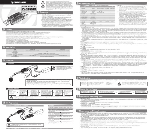
0103Specifications04User Guide05ESC Programming06Programmable Items07Data CheckingProgrammable Item List of Platinum 60A V4 ESC. (“*” in the form below indicate factory defaults. )USER MANUALPLATINUM 120A V4 / 80A V4Brushless Electronic Speed Controller1. Flight Mode:1.1 In “Fixed-wing” mode, the motor will start up when the throttle amount reaches 5% or above. There is no soft start-up, the motor responds to the throttle increase rapidly.1.2 In “Helicopter (Linear Throttle)” mode, the motor will start up when the throttle amount reaches 5% and it will start up in a soft way with the throttle (from 0 to 100%) acceleration time is fixed to 3.5 seconds . It will accelerate to the RPM corresponds to the specific throttle amount at the fixed rate.1.3 In “Helicopter (Elf Governor)” mode, the motor will start up when the throttle amount reaches 40% or above. And it will complete the speed standardization and enter thespeed-governing operation in the preset start-up time (4~25s). In this mode, the motor will standardize its speed every time it starts up. Due to different discharge rates/capabilities of different batteries, the RPM you standardize each time may be a little different.In consequence, at the same throttle amount, the RPM may be a bit different when using different batteries, but this won’t affect the speed-governing effect.1.4 In “Helicopter (Store Governor)” mode, the motor will start up when the throttle amount reaches 40% or above. It will also start up in a very soft way. And it will also complete the speed standardization and enter the speed-governing operation in the preset start-up time. In this mode, the motor will only standardize its speed the first time when it starts up. When performing RPM standardization for the first time, we recommend using afully-charged battery with good discharge capability. After the RPM standardization, change another battery to fly your aircraft. At the same throttle amount, the RPM should be the same as the RPM of the first flight. For consistent control feel, we recommend using this mode.The motor will beep a long beep to indicate • High performance microprocessor for excellent motor speed-governing and super soft start-up.• Microprocessor powered by independent DC regulator has better anti-interference performance, which greatly reduces the risk of losing control.• DEO (Driving Efficiency Optimization) Technology adopted greatly improves throttle response & driving efficiency, reduces ESC temperature.• New switch-mode BEC with adjustable output voltage ranges from 5V to 8V and continuous/peak current of 10A/25A.• BEC is separated from other circuits of the ESC, it will keep its normal output when the MOSFET board of the ESC is burnt. • Multiple flight modes: Fixed-wing, Helicopter (Linear Throttle), Helicopter (Elf Governor) , Helicopter (Store Governor).• New governor program with adjustable governor parameter P/I brings excellent speed-governing effect, guarantees the stability of the propeller’s revs when the load changes dramatically. • Data logging records the standardized RPM, minimum voltage and maximum temperature of the flight.• "Restart in auto rotation" can manually interrupt the auto rotation and quickly restart the motor to avoid crashes caused by incorrect operations. • Independent output port for RPM (that is: motor speed) signals.• Separate programming port for ESC programming or parameter setting.• WIFI module (sold separately) for programming the ESC wirelessly with your smart phone (IOS or Android).• Online data checking, ESC programming, firmware upgrade (Multifunction LCD program box or WIFI Express is needed) supported.• Multiple protections like start-up protection, ESC thermal protection, capacitor thermal protection, over-current protection, overload protection, and throttle signal loss protection.Throttle Signal/BEC Output/RPM Signal Transmission WiresSeparate Programming PortPlatinum 80A V4Switch-mode, 5-8V Adjustable (Step: 0.1V), 10A/25A Cont./PeakWhite Throttle Signal Wire/Red & Black BEC Output Wires/Yellow RPM Signal Transmission Wire450-500 Class Helicopters(Propeller: 380-470mm)80A/100A84.29x38.2x20.4mm / 96.5gProgrammingConnect the LCD program box and a battery to your ESC as shown above.successfully connected to your ESC.relates to the ESC.main blades =R ÷ Motor Poles ÷ 2 ÷ Gear Ratio × Throttle Amount (%).Program Your ESC with a WIFI Express: For detailed information, please refer to the user manual of WIFI Express.The ESC will record the standardized RPM, minimum voltage, maximum current and maximum temperatures of the flight but won’t save these data, so you need to keep the ESC on if you want to check the information of the flight.08Normal Start-up ProcessTurn on the transmitter, and then move the throttle stick to the bottom position.After connected to a battery, the ESC will emit “♪123” indicating it’s normally powered on.The motor will emit several beeps to indicate the number of LiPo cells.The motor emits a long beep indicating the ESC is ready to go.09Explanations for Warning Tones1. Input voltage is abnormal:The ESC will measure the input voltage the moment when it’s powered on. The motor will keep beeping “BB, BB, BB” (the interval between two BBs is 1 second) when the input voltage is beyond the normal range. The warning tone won’t stop until the voltage turns normal. 2. Throttle signal loss protection is activated:The motor will beep “B-, B-, B-” (the interval between two B-s is 2 seconds) when the ESC doesn’t detect any throttle signal. 3. Throttle stick is not at the bottom position:The motor will beep “B-B-B-B-B-” when the throttle stick is not moved to the bottom position.4. Throttle range is too narrow:The motor will beep “B-B-B-B-B-” when the throttle range you set is too narrow (when designing this ESC, it requires that the entire throttle range you set cannot be less than 50% of the whole throttle range available on the transmitter.) The warning tone indicates the throttle range you set is void and you need to set it again.10Explanations for Multiple Protections1. Start-up Protection:The ESC will monitor the motor speed during the start-up process. When the speed stops increasing or the speed increase is not stable, the ESC will take it as a start-up failure. At that time, if the throttle amount is less than 15%, the ESC will automatically try to restart up; if it is larger than 15%, you need to move the throttle stick to back the bottom position and then restart up the ESC. (Possible causes of this problem: poor connection/ disconnection between the ESC and motor wires, propellers are blocked, etc.)2. ESC Thermal Protection:The ESC will gradually reduce the output but won’t cut it off completely when the ESC temperature goes above 110 . For ensuring the motor can still get some power and won’t cause crashes, so the maximum reduction is about 50% of the full power. The ESC will gradually resume its maximum power after the temperature lowers down. In addition, the ESC temperature cannot exceed 70℃ when it’s powered on. Otherwise, it cannot be started up. (Here we are describing the ESC’s reaction in soft cutoff mode, while if in hard cutoff mode; it will immediately cut off the power.) 3. Capacitor Thermal Protection:The ESC will activate this protection when the operating temperature of capacitors goes over 130 . It protects capacitors in the same way as the ESC thermal protection does to the ESC .4. Throttle Signal Loss Protection:When the ESC detects loss of signal for over 0.25 second, it will cut off the output immediately to avoid an even greater loss which may be caused by the continuous high-speed rotation of propellers or rotor blades. The ESC will resume the corresponding output after normal signals are received. 5. Overload Protection:The ESC will cut off the power/output or automatically restart itself when the load suddenly increases to a very high value. (Possible cause to sudden load increase is that propellers are blocked.)6. Over-current Protection :The ESC will cut off the power when the current gets close to the short circuit current (of 300A). This protection may be activated by the burnt motor or some others.Program Your ESC with a Multifunction LCD Program BoxAbout RPM Standardization & OthersI. The motor will enter the soft start-up when user switches the throttle amount from 0 to 40% or above (50% throttle is recommended). The pitch of main blades should be 0 degree during the soft start-up process, the RPM standardization completes when the soft start-up ends, and the ESC makes the motor enter the speed-governing state. In “Helicopter (Store Governor)” mode, if user wants to re-standardize the speed, he needs to set the flight mode to “Helicopter (Elf Governor)” and save this mode first, and then reset the flight mode back to “Helicopter (Store Governor)”, then the ESC will re-standardize the motor speed when the motor rotates for the first time after the ESC is powered off and then on again.II. For ensuring the speed-governing effect, we recommend setting the throttle amount to 85% or below in both speed-governing modes (Helicopter (Store Governor) & Helicopter (Elf Governor)), so there will besufficient compensating room to maintain the consistency of the RPM. We recommend replacing the motor or adjusting the gear ratio if the expected RPM still cannot be reached when the throttle amount exceeds 85%. (Note: You need to re-standardize the RPM after replacing the motor, blades, body frame or adjusting the gear ratio.)III. In “Helicopter (Store Governor)” mode, if you fly your aircraft with another pack that has poor discharge capability after the RPM standardization (with a pack which has good discharge capability), the pack has poor discharge capability will get damaged.IV. In “Helicopter (Store Governor)” mode, different battery packs can bring the same stable RPM only if they have the same cell count. This won’t change even when you change the battery pack. However, battery packs with different cell count don’t have the same effect. For instance, in “Helicopter (Store Governor)” mode, you can not use a 4S to calibrate the motor RPM and then use a 6S to drive the motor, hoping it can run at the same RPM.V. User can decide the control feel via adjusting Governor Parameter P/I. In “Helicopter (Store Governor) or Helicopter (Elf Governor)” mode, connect your ESC to a smart phone or PC, then you can check the throttle vs speed chart.2. LiPo Cells:The ESC will automatically calculate the number of LiPo cells you have plugged in as per the “3.7V/Cell” rule if “Auto Calc.” is selected. Or user can set this item manually. 3. Voltage Cutoff Type:The ESC will gradually reduce the output to 50% of the full power in 3 seconds after the voltage cutoff protection is activated, if soft mode is selected. . It will immediately cut off all the output when hard mode is selected. 4. Cutoff Voltage:2.8V-3.8V (custom), 3.0V (default).5. BEC Voltage:5-8V (adjustable), 0.1V (step), 6V (default).6. Start-up Time:4-25s (adjustable), 1s (step), 15s (default). (Note: It only functions in Helicopter (Store Governor) and Helicopter (Elf Governor))7. Governor Parameter P:Control the ESC maintaining the stability of the current motor speed. 8. Governor Parameter I:Control the dynamic response. To be specific, control the supplement extent when the actual motor speed is below expectation. If you choose a very big value, then the supplement may be too much. If select a very small value, then the supplement may not sufficient.9. Auto Restart Time:the ESC will cut off its output when the throttle amount is between 25% and 40%. If you increase the throttle amount to above 40% within preset time period (0-90s), the motor will rapidly start up and accelerate to the speed (in the programmed Restart Acceleration Time) corresponds to the specific throttle amount, complete the shutdown and restart up . If you move the throttle stick to over 40% beyond the preset time period, the ESC will enter the soft start-up process. (Note: This function won’t effect unless the throttle amount is over 25% and it only effects in “Helicopter (Store Governor) and Helicopter (Elf Governor)” mode.)10. Restart Acceleration Time:1-3s (adjustable), 0.5s (step), 1.5s (default). This item controls the time the motor will cost to restart and accelerate to the full speed. (This function only effects in “Helicopter Governor Elf/Store” mode) 11. Brake Type:11.1 Proportional Brake: when the throttle range on the transmitter is between 20% and 100%, the corresponding ESC throttle output is between 0% and 100%.When the throttle range on the transmitter is between 20% and 0%, the corresponding brake force is between 0 and 100%.11.2 Reverse: after selecting this option, the RPM signal wire will turn into a reverse signal wire (the signal range is in line with the throttle range). After setting a channel on the transmitter, when the reverse signal length is above 20% signal length, the Reverse mode will be activated. The reverse signal length must be below 20% signal length when the ESC is powered on for the first time. When the reverse signal length is below 20% signal length, 0-100% throttle corresponds to “CW”; when the reverse signal length is above 20% signal length, the motor will stop spinning CW (and then spin CCW); at this time, 0-100% throttle corresponds to “CCW”. Any signal loss will activate the throttle signal loss protection, no matter it happens to the RPM signal wire or the throttle signal cable during the flight.12. Brake Force:0-100% (adjustable), 1% (step), 0 (default). (Note: this function only effects in “Normal Brake” mode.)13. Timing:0-30° (adjustable), 1° (step), 15° (default).14. Motor Rotation:CW/CCW. User can adjust this item via a multifunction LCD program box.15. DEO (Freewheel):User can decide this function “Enabled” or “Disabled” in “Fixed Wing” mode or in “Helicopter (Linear Throttle)” mode. This item has been preset to “Enabled” and cannot be adjusted in “Helicopter (StoreGovernor) and Helicopter (Elf Governor)” mode. This function can brings better throttle linearity.20161227。
时间控制器说明书
时间控制器说明书时间控制器说明书1:简介时间控制器是一种用于控制定时任务的设备,它通过设定时间参数,实现对其他设备的开关、调节等操作。
本说明书旨在为用户提供详细的操作步骤和注意事项,以帮助用户正确使用时间控制器。
2:产品规格时间控制器的规格如下:- 尺寸:毫米 x 毫米 x 毫米- 重量:克- 输入电压:AC V- 最大载荷电流:安培- 工作温度:-°C 至 +°C3:组件及功能时间控制器由以下组件组成,每个组件都具有特定的功能:3.1 显示屏:用于显示当前时间和设置参数。
3.2 按钮:用于选择菜单和操作参数设置。
3.3 开关:用于手动控制设备的开关状态。
3.4 时间调节按钮:用于调节时间参数。
4:安装步骤在安装时间控制器之前,请确保断开电源,并按照以下步骤进行操作:4.1 将时间控制器固定在所需的位置,并确保其安装牢固。
4.2 连接电源线,并确认电源线的连接正确无误。
4.3 打开电源,启动时间控制器。
5:使用说明时间控制器具有以下功能:5.1 时间设置:通过按下时间调节按钮,在显示屏上设置当前时间。
5.2 定时开关:在定时菜单下,选择开关状态和时间参数,实现设备的定时开关。
5.3 循环定时:在循环定时菜单下,选择循环周期和设备操作时间,实现设备按照设定周期循环运行。
5.4 周期调节:在周期调节菜单下,选择设备的工作周期和休息周期,实现设备的定期工作和休息。
5.5 手动开关:通过手动操作按钮,实现对设备的开关控制。
6:常见问题解答以下是一些常见问题的解答,供用户参考:6.1 时间显示不准确:请确保设置的当前时间准确无误,并检查电源是否正常。
6.2 定时任务无法执行:请确认定时任务的时间参数是否正确,并检查设备的接线是否正确。
6.3 时间控制器无法正常工作:请检查电源是否正常,如果问题仍然存在,请联系售后服务。
7:附件本文档涉及的附件包括:- 时间控制器使用手册- 时间控制器安装图纸8:法律名词及注释本文档中涉及的法律名词及其注释如下:- AC:交流电(Alternating Current),指电流在正负方向上交替变化的电力。
- 1、下载文档前请自行甄别文档内容的完整性,平台不提供额外的编辑、内容补充、找答案等附加服务。
- 2、"仅部分预览"的文档,不可在线预览部分如存在完整性等问题,可反馈申请退款(可完整预览的文档不适用该条件!)。
- 3、如文档侵犯您的权益,请联系客服反馈,我们会尽快为您处理(人工客服工作时间:9:00-18:30)。
★轻触按键设定仪表参数,操作极其简单,避免了拔码 型仪表易坏的缺点;
★具有手动自动复位,掉电保持计数值、参数锁定保 护功能;
★可自由设定延时输出时间;★外供DC12V电源;
★适合应用于包装机械、食品机械、木工机械等行业;
HE系列时间控制器使用说明书
一、基本特点
四、型号说明
二、仪表技术指标
三、操作面板说明
五、仪表的操作说明
供电电源整机功耗
继电器触点容量继电器寿命绝缘电阻强度环境条件输入信号输入阻抗延时时间定时范围
AC220V±10% 50/60Hz <3W
250VAC/3A或30VDC/5A 机械寿命:500万次;
电气寿命:10万次(额定负载内)
≥20M Ω;1.5KV/1M
-10~50℃(不结冰);35~85% RH(湿度)方波、正弦波脉冲信号2V≤H≤30V:0≤L≤1V
≥10K Ω
0.001S ~999999H
0.001S ~999.999S; 1M ~999999M;0.01S ~9999.99S; 1H ~999999H;0.1S ~99999.9S; 1S ~9999M59S;1S ~999999S; 1S ~99H59M59S;
A、SET:设定键及确认键 ; :左移键; :减键; ▲:增加键; RST键:复位键
B、在操作菜单参数过程中,同时按 +▲键可退出参数 设定并保存
(预置值设定)
小时灯秒灯分钟灯
面板按键锁OUT预置值
密码锁
定时范围
停电记忆
输出模式
定时模式注:修改参数方法:按 鍵令下排闪动,
再 键修改,后按SET 鍵確認剛修改的參數。
注:若本接線图与实际仪表接線图有
差别, 请您按实际仪表接線图接線。
8.1 接線注意事项
8.2 接線范例
8.3 输出方式逻辑图
(1)输入导線不宜过长,建议输入線使用屏蔽線。
(2)输入信号線应远离仪表电源線,动力电源線和负荷線,以避免产生杂讯干扰。
(3)对电气回路和非带电金属体进行耐压实验等场合,请将计数器从回路拆下或短路(有可能损坏CMOS电路)
★RST为复位端子为高电平触发
★CPIN为触发端子为低电平触发
输出输出
說明:1.當CON 設為PAU 時,控制端短接可以暫停計是時。
2.当CON 设为TR1时,控制端短接一下可触发计时,或暂停计时。
六、仪表外型及安装开孔尺寸。