Mentor EN2004 ( Board Station ) 中文简明教程
Mentor PCB软件入门级操作教程
MENTOR软件操作教程目录一、Mentor设计界面和环境 (2)1、打开MEMTOR及界面介绍: (2)2、常用菜单介绍: (3)3、 Expedition PCB项目设置: (5)二、PCB的前处理。
(12)1、软件的打开 (12)2、导入DXF。
(12)3、点击菜单栏File---Import进入下面的菜单; (12)4、工程文件(原理图)、库文件、网表的导入。
(12)5、板框的制作和层数的定义。
(13)6、过孔的制作。
(15)7、定位孔的制作 (17)8、Mark点的制作。
(19)一、Mentor设计界面和环境1、打开MEMTOR及界面介绍:打开图标,进入下面的界面;单机操作时,选第一个操作,其余全不选,多人协作勾选选项,其余全不选。
点击OK进入软件。
2、常用菜单介绍:①File②Edit③View ●Undo---撤销上一步操作。
●Redo---重复上步操作。
●Copy Bitmap to Clipboard---将选中对象复制到剪切板。
或者用笔画命令●Select All---全选(Ctrl+A).●Add to Select Set---对选中的对象执行其子选项中的操作,如锁定等。
●Find---查找。
如查找器件、网络等。
●Review---检查设计状态、冲突、最小距离、焊盘等。
●Place---摆放如图中子选项中的对象。
●Fix/Semi Fix/Unfix---固定选中的对象/半固定选中的对象/解除固定。
●Lock/Unlock---锁定选中的对象/解除锁定。
●Highlight/Unhighlight/Unhighlight All---高亮选中的对象/解除选中对象的高亮/去除全部高亮。
●Delete/Delete all Traces and Vias---删除选定对象/删除所有连线和过孔。
④Setup⑤Place⑥Planes●Display Contral---显示控制。
PROTEL_2004_项目实训全--教案

《PROTEL 2004 项目实训》教案教师姓名 XX 所任年(班)级科目 Protel 2004 项目实训所授班级学生基础及能力情况分析:该门课程所授班级为机电班和机维班,该部分学生已经在高一学习了电工基础的知识,基本上会看原理图,但掌握的还不够,具体表现在会看,看不会拆分功能模块,简单的图看的懂,复杂的图不会分析。
电路板上的电路看不懂,不会分析。
但对于实际操作,如电路板的模拟制作,应该能激发学生一定的兴趣。
教材分析及教学总体设想:protel是中等职业技术学校机电专业核心教学与训练课程,是一门实践性很强的集理论与实践操作于一体的主干课。
本课程主要任务是使学生全面了解原理图及PCB图的绘画、电路板的制作。
学期教学目的要求:熟悉Protel 2004的文件组织结构;学会PCB工程、原理图文件、PCB文件等的创建、保存和改名;对集成元件库进行加载与卸载;根据要求查找相应的元器件;学会元器件、导线、节点、电源和接地组件等的放置、移动和旋转及其属性的设置;按要求对元器件进行布局,学会元器件参数位置的调整;熟练掌握元器件的查找与放置功能;学会总线、总线分支线的放置与属性编辑;进行元器件引脚属性的设置和引脚位置的调整;理解多部件元器件的基本组成及其放置和引脚的编辑;学会“自上而下”和“自下而上”层次原理图的设计及利用图纸连接器进行原理图的设计;理解SCH Library工作面板中的各项内容,并能进行相关操作;学会多部件元器件符号的制作、修改及添加封装;根据原理图生成网络表,并能看懂网络表所包含的内容;学会自动布局和手动布局的操作方法;掌握布线规则的设置和自动布线的操作方法;掌握PCB 和原理图文件双向更新的相关操作;掌握元件封装的命令与创建方法;掌握参考点的设置方法;学会对已创建的元件封装,按实际要求进行修改;熟悉向导中元件封转的种类。
学期教学重点及难点:对集成元件库进行加载与卸载;熟练掌握元器件的查找与放置功能;进行元器件引脚属性的设置和引脚位置的调整;理解多部件元器件的基本组成及其放置和引脚的编辑;学会“自上而下”和“自下而上”层次原理图的设计及利用图纸连接器进行原理图的设计;理解SCH Library工作面板中的各项内容,并能进行相关操作;学会自动布局和手动布局的操作方法;掌握PCB和原理图文件双向更新的相关操作;掌握元件封装的命令与创建方法。
Protel2004演示文稿清单
Protel 2004 EDA技术及应用演示文稿清单章节幻灯片幅数封面 6第1章42第2章78第3章70第4章62第5章45第6章68第7章75第8章56第9章178第10章67第11章92第12章47合计886前言第1章Protel2004基础11.1 Protel2004概述11.1.1 Protel2004的主要组成11.1.2 Protel2004的特性11.1.3 Protel2004的系统配置21.1.4 Protel2004的安装及文件组成31.2 Protel2004的操作界面31.2.1 Protel2004的菜单栏41.2.2 Protel2004的主页61.2.3 Protel2004的工作面板61.3 Protel2004项目文件的管理81.3.1 新项目文件的建立91.3.2 打开和编辑已有的项目文件111.3.3 项目文件的组织141.3.4 关闭文件141.4 设置项目选项141.4.1 ErrorReporting(错误报告)151.4.2 ConnectionMatrix(连接矩阵)151.4.3 Comparator(比较器)151.4.4 ECO(工程变化顺序)161.4.5 Options(选项)161.4.6 Multi Channel(多通道)171.4.7 DefaultPrints(设置项目打印输出)171.4.8 Searchpaths(搜索路径)181.4.9 编译项目18练习题19上机实践19第2章绘制单管放大电路原理图202.1 创建设计项目文件和原理图文件20 2.1.1 电路原理图的设计流程202.1.2 创建设计项目文件212.1.3 创建原理图文件222.2 原理图图样参数设置232.2.1 “SheetOptions”选项卡232.2.2 “Parameters”选项卡272.3 原理图设计工具栏及画面调整282.3.1 原理图设计工具栏282.3.2 图样的放大与缩小302.4 装载元器件库和放置元器件312.4.1 元器件库管理器312.4.2 查找元器件322.4.3 装载元器件库332.4.4 放置元器件342.5 元器件的属性编辑和位置调整372.5.1 编辑元器件属性372.5.2 向元器件添加新的模型392.5.3 元器件位置的调整412.6 连接线路462.6.1 “Wiringtools”工具栏462.6.2 连接导线472.6.3 放置线路节点492.6.4 保存原理图文件49练习题50上机实践50第3章绘制振荡器与积分器电路原理图51 3.1 创建设计项目文件和原理图文件51 3.1.1 创建设计项目文件513.1.2 创建原理图文件523.1.3 设置图样大小523.2 装载元器件库和放置元器件543.2.1 装载元器件库543.2.2 放置元器件543.2.3 放置电源和接地符号553.2.4 编辑元器件属性563.3 元器件的排列573.3.1 左对齐573.3.2 右对齐583.3.3 按水平中心线对齐583.3.4 水平均布583.3.5 顶端对齐593.3.6 底端对齐593.3.7 按垂直中心线对齐593.3.8 垂直均布593.3.9 同时进行综合排列或对齐593.4 放置连线和节点603.4.1 放置连线603.4.2 放置节点613.5 放置网络标号和I/O端口623.5.1 放置网络标号623.5.2 放置I/O端口633.6 美化原理图653.6.1 绘图工具命令653.6.2 绘制直线653.6.3 绘制多边形663.6.4 绘制圆弧673.6.5 绘制椭圆弧673.6.6 绘制Bezier曲线683.6.7 放置注释文字693.6.8 放置文本框693.6.9 绘制矩形与圆角矩形703.6.10 绘制圆与椭圆713.6.11 绘制扇形图723.6.12 美化振荡器与积分器电路原理图73 练习题74上机实践74第4章绘制单片机最小系统原理图754.1 绘制单片机最小系统单张原理图75 4.1.1 创建PCB设计项目文件754.1.2 创建原理图文件764.1.3 设置图样大小764.1.4 装载元器件库764.1.5 放置元器件并进行布局调整784.1.6 连接线路794.2 层次式原理图的设计804.2.1 层次式原理图概述804.2.2 层次式原理图的设计方法824.3 多通道电路设计874.3.1 设计多通道电路874.3.2 由多通道电路产生网络表90 4.3.3 查看多通道原理图914.3.4 通道的切换92练习题94第5章原理图电气检查及报表95 5.1 电气连接检查955.1.1 设置电气连接检查规则95 5.1.2 检查结果报告975.2 创建网络表975.2.1 设置网络表选项985.2.2 产生网络表995.2.3 Protel网络表格式1005.3 产生元器件列表1005.3.1 元器件清单报表1015.3.2 元器件交叉参考表1025.3.3 简易元器件材料表1035.4 生成层次表1045.4.1 元器件交叉引用参考报表104 5.4.2 层次报表1075.4.3 端口引用参考1085.5 批量输出工作文件1085.5.1 创建输出任务配置文件109 5.5.2 输出配置1095.5.3 数据输出1105.6 原理图输出1115.6.1 页面设置1115.6.2 打印机设置1125.6.3 打印预览1125.6.4 打印112练习题113上机实践113第6章电路仿真1146.1 仿真元器件库1146.1.1 常用仿真元器件库1146.1.2 仿真信号源元器件库1146.1.3 仿真专用函数元器件库116 6.1.4 仿真数学函数元器件库116 6.1.5 信号仿真传输线元器件库116 6.1.6 元器件仿真属性编辑1176.1.7 仿真源工具1176.2 仿真设置1186.2.1 节点电压设置1186.2.2 初始条件设置1186.2.3 仿真器的设置1196.3 运行电路仿真1256.3.1 对电路图进行仿真分析的方法步骤125 6.3.2 电路仿真举例126练习题134上机实践134第7章集成元器件库的创建与管理1357.1 原理图元器件库编辑器1357.1.1 打开原理图元器件库编辑器1357.1.2 绘图工具1367.1.3 IEEE工具1377.1.4 元器件库编辑管理器1387.2 创建原理图元器件1397.2.1 绘制原理图元器件1397.2.2 复制导入元器件1437.2.3 原有元器件编辑修改1447.2.4 给元器件添加一个别名1467.2.5 元器件报表1467.2.6 产生元器件规则检查报表1467.2.7 产生元器件库报表1477.3 创建PCB元器件封装1487.3.1 启动PCB元器件封装库编辑器148 7.3.2 手工创建元器件封装1497.3.3 利用向导创建元器件封装1527.4 PCB封装库管理器1557.4.1 PCB元器件库管理器面板1557.4.2 元器件封装管理器的应用1577.5 创建集成库1587.5.1 准备基本元器件库文件1587.5.2 创建集成库项目文档1607.5.3 为集成库项目文档添加源库文件160 7.5.4 编译集成库项目文档162练习题162上机实践163第8章印制电路板(PCB)设计基础164 8.1 印制电路板概述1648.1.1 印制电路板的分类1648.1.2 印制电路板的结构1658.1.3 元器件封装1668.2 PCB图设计流程及遵循原则1678.2.1 PCB图设计流程1688.2.2 印制电路板设计应遵循的原则168 8.3 PCB的文件管理和工具栏1718.3.1 PCB的文件管理1718.3.2 PCB的工具栏1738.3.3 印制电路板的3D显示1758.4 PCB参数设置1778.4.1 启动PCB参数设置对话框177 8.4.2 PCB参数设置177练习题182第9章PCB单面布线设计1839.1 新建PCB文件1839.1.1 使用PCB向导创建新的文件183 9.1.2 将PCB文件添加到设计项目186 9.2 规划印制电路板1879.2.1 Protel2004工作层的设置1879.2.2 印制电路板的选项设置1909.2.3 定义印制电路板的形状及尺寸191 9.3 装载元器件封装库的操作1929.3.1 装载元器件库1929.3.2 浏览元器件库1939.3.3 搜索元器件库1939.4 网络与元器件的装入1959.4.1 编译设计项目1959.4.2 装入网络与元器件1959.5 放置元器件封装1969.5.1 元器件封装的放置1969.5.2 设置元器件封装的属性1989.5.3 元器件封装的修改1999.6 放置导线2009.6.1 放置导线操作2009.6.2 导线的修改和调整2019.6.3 导线的删除2029.6.4 设置导线属性2029.7 放置焊盘2039.7.1 焊盘的放置2039.7.2 焊盘的属性设置2039.8 放置导孔2059.8.1 导孔的放置2059.8.2 设置导孔属性2059.9 放置文字2069.9.1 放置文字的操作2069.9.2 设置文字属性2069.10 放置坐标指示2079.10.1 放置坐标指示2079.10.2 坐标指示属性设置2079.11 放置尺寸标注2089.12 放置相对原点2099.13 放置圆弧导线2099.13.1 圆弧导线的放置2099.13.2 圆弧导线属性的设置2119.13.3 圆弧导线的移动和调整2129.14 放置矩形铜膜填充2139.14.1 矩形铜膜填充的放置2139.14.2 设置矩形填充属性2139.14.3 矩形铜膜填充的修改2149.15 放置多边形敷铜2149.15.1 放置多边形敷铜2149.15.2 放置敷铜2169.15.3 调整敷铜2169.16 分割多边形敷铜2179.17 放置屏蔽导线2179.18 放置泪滴2189.19 自动布局2189.20 手工编辑调整元器件的布局2209.20.1 选取元器件2209.20.2 元器件封装的基本操作2219.20.3 排列元器件2249.21 自动布线2259.21.1 设置布线规则2259.21.2 自动布线操作226练习题229上机实践229第10章PCB双面布线设计23010.1 创建PCB图文件23010.1.1 打开“振荡器与积分器-PRJPCB”项目文件230 10.1.2 新建“振荡器与积分器-PCB”文件23010.1.3 定义印制电路板形状及尺寸23110.2 放置元器件封装23210.2.1 装载元器件库23210.2.2 装入网络与元器件23210.2.3 添加网络连接23310.3 手动布线和自动布线23610.3.1 手动布线23610.3.2 自动布线23810.4 手工调整印制电路板23910.4.1 调整元器件24010.4.2 调整布线24010.4.3 调整焊盘24010.4.4 电源/接地线的加宽24110.4.5 对印制电路板敷铜24110.4.6 文字标注的调整24210.4.7 补泪滴处理245练习题246上机实践246第11章设计规则及检查24711.1 设计规则24711.1.1 PCB设计规则和约束编辑对话框247 11.1.2 与电气相关的设计规则24811.1.3 与布线有关的设计规则25011.1.4 与SMD布线有关的设计规则255 11.1.5 与焊盘延伸量有关的设计规则256 11.1.6 与内层有关的设计规则25711.1.7 与测试点有关的设计规则26011.1.8 与印制电路板制造有关的设计规则262 11.1.9 与高频电路设计有关的规则26411.1.10 与元器件的布局有关的规则266 11.1.11 信号完整性分析26911.2 设计规则向导27211.3 设计规则检查273练习题275第12章PCB报表与输出27612.1 生成的PCB报表27612.1.1 生成印制电路板信息报表27612.1.2 生成元器件清单报表27712.1.3 生成元器件交叉参考表28012.1.4 生成项目文件层次报表28012.1.5 生成网络状态表28112.1.6 生成网络表28212.1.7 生成元器件插置文件28212.1.8 生成测试点报表28312.1.9 生成底片文件28412.1.10 生成数控钻文件28512.1.11 其他报表28612.2 PCB图打印输出28812.2.1 打印属性设置28812.2.2 打印机设置28812.2.3 打印289练习题291上机实践292附录常用元器件图形符号293 参考文献299。
高压软起使用手册(奥博)-EN04
AMVS computerized softstarter withChineseDisplayfor MV AC motorUserManualNanjing Aubo Electric Co.LtdProduct Feature:AMVS is the computerized digital soft starter for MV AC motor , with Chinese display. Its system uses the advanced single chip microcomputer, PLC controller and color touch screen HMI and high voltage power electronic semiconductor devices and modern control technology to integrate a new type of product of solid state starter and running protection of MV AC motor. In addition to the excellent starting function, this product also has a perfect comprehensive protection function of the motor running, can ensure that the motor and mechanical transmission equipment running in a safe and reliable operation of the various circumstances. Compared with other types of medium voltage motor soft starter (such as water resistance type), the soft starter consumes less energy in the process of starting , therefore it has the obvious energy saving effect, and itcan be used in the occasion of frequent starting. At the same time, since the soft starter is made of solid state devices, it has the long-term use of free maintenance, and a small equipment size, easy to move and a better vibration resistance as clear advantages. Further more, it has the following unique features and obvious advantages, becoming the ideal replacement of other traditional medium voltage soft starter.1.Starting of initial voltage can be set according to the actualsituation and need flexibly, as low as to 15% of the supply voltage, and the highest could be 90%, make the motor have a larger starting torque and small starting current, reducing the equipment operation requirement for power grid capacity, saving the investment of equipment. Reduce the impact stress to the motor and to the mechanical transimission part itself, and can prolong the service life of motor and transmission machinery.2.When starting, the initial start voltage, the start time andstarting current limit and so on, are available on color LCD touch screen to be easily set up and be implemented, and soft stop deceleration time can be set freely according to the requirementsslowing down and stop condition of equipment and motor.3. variety of starting mode ( reduced voltage starting ,constantcurrent starting) control to meet the various startingperformance requirements of the device.4.Perfect motor running protection function, can ensure the safetyof the equipment operation, protection function are like:a. protection alarm for input supply voltage high.b. protection alarm for input supply voltage low.c. the input power phase loss alarm.d. motor overload alarm for inverse time over current protection .medium voltage motor imbalanced current alarmf. motor start excess time protection alarm.g. the bypass contactor fault alarm.h. residual current leakage alarm for the equipment.i. the main three-phase thyristor power device breakdown damagealarm and display.j. short circuit instantaneous tripping alarm (which can be classified as current transformer range 0.1- 2.5 times current).5.The soft starter shows motor three-phase working current and theresidual current leakage, and the voltage of power supply, anddisplays the total motor running time, which is not affected bypower outages, to facilitate the understanding of the equipmentrunning total time, easy to carry out regular maintenance.6.The running parameters of display are colored Chinese touch screenman-machine interface, easy parameters setting is veryintuitive.7.According to user requirements it can privide profibus dpcommunication interface, and remote monitor computer networkingcommunication at the next higher level and to realize the remotecontrol.(please notify when ordering for other communicationneed)Touch screen panel shows the various parameter setting.The function description:Running time (RUNtime) : 0-9999 hour (H); The count value is for all previousrun time accumulated, after 9999 hours fullvalue, it goes automaticallyback tozero.Every time after restart, the timingcounts again.Start Time: The unit is seconds; 0.1 99.9 seconds (S)Stop Time: The unit is seconds; 0.1 99.9 seconds (S)Overcurrent: The unit is A; it is generally set as about 1.2 times of rated current of motor nameplates.In the process of motorstarting, it doesn't work.When the soft starter goes into runstate, if the motor current is the same or more than the value,the controller will count the timing of inverse timeoverload .When it achieves the time set by overload time, thesoft starter will stop working and generate overload alarmsignal.overload time: 0.1-199.9 seconds (S); When the motor current exceed theset overload current value, such as thetime more than the set time,it producesoverload alarm. This time has theinverse time protection characteristics,that is, when the actual current exceedsthe set overload current value, the greaterthe current, the shorter the protectiontime.start voltage: range: 10-90%; When starting voltage is corresponding to 10% 90% of the power supply voltage , the user can adjustit according to actual situation of devices.Residual current: The unit of the value is A, which is the actual signal detected from the residual current transformer, witha range of 0.01-9.99 A.The value displayed is the actualresidual current detected by the residual currenttransformer, which cannot be modified. When the userreplaces the transformer with different type, he must adjustP4 potentiometer of the control board to calibrate it.Start current limit: The unit is A: the current value is the maximum current value in the process of starting a motor.In theprocess of starting, when the motor starting current reachesthe value, the starter will limit the increase of thestarting current, the starting time value being the biggestprotection time.If due to the reason of too heavy load, thestart can not be completed in the set starting time, thestarter will stop and generate "starting overtime" alarm.If the equipment is normal, this can be resolved byincreasing the current limit value or increasing thestarting time. Please pay attention to this! The largest setvalue shall not exceed two times of the "mutual inductancecurrent" set value! When the start mode is selected as“reduced voltage", the parameter value is invalid.Current leakage protection: The unit of the value is A, with a range of 0.01-9.99 A.The set values is the trigger value ofleakage current protection.When the value is set to 0.00A, the function is invalid.This value is the value detectedby the residual current transducer on the output side ofsoft starter. When the output cable or the medium voltagemotor has a bad insulation to the ground and causes leakagecurrent to ground, if the leakage current detected isgreater than the set value, and duration time is greaterthan the set leakage time, the soft starter will immediatelystop and produce a fault alarm on the display(leakageblocking protection alarm) .When it is used for the firsttime, the value can be set to a maximum first. At the firststarting of equipment, the user should observe the maximumleakage current (usually during start), and the averageleakage current during run. When it comes to stop, set theparameter to a value 20-30% greater than the actual leakagecurrent .Current leakage delay: The unit of the value is second, with a range of 0.1-9.99 second.The set values is the delayvalue of leakage current protection.When the value is setas 0.0 seconds, it is the instantaneous protection action .Due to all kinds of complicated conditions of transmissioncable and medium voltage motor, the leakage current isbigger during start and is smaller during run, so settingthe appropriate time delay of the protection willeffectively avoid mis-operation of the leakage protection,that is, when the leakage current is beyond the above item ,the user should notice this.The leakage time delay functionbecomes invalid once the motor goes into run mode normally.Once the leakage current exceeds the set leakage currentprotection value, the soft starter will immediately stopand produce an alarm on the display (leakage blockingprotection alarm).Over voltage protection: The unit is KV: this parameter is to protect the device from working with too high power supply voltage.Generally it can be set at + 20% to + 25% higher than ratedvoltage .When the supply voltage exceeds the set value, thesoft starter will produce fault alarm on thedisplay.(power supply over voltage alarm)Under voltage protection: The unit is KV: this parameter is to protect the device from working with too low power supply voltage.Generally it can be set at -35% lower than the ratedvoltage .When the supply voltage is below the set value,the soft starter will produce fault alarm on thedisplay.(power supply under voltage alarm)Transducer current: The unit is A: this parameters is the internal transducer data set by manufacturer, which is only to bemodified after the engineer input the password.start mode: Normal mode: in this mode, the motor starts from the "initial voltage", a set low voltage , according to a setstart time to improve output voltage linearly, until theend of start time.Low-frequency mode: especially suitable for the equipmentwith large mechanical friction and larger mechanicalinertia .In this case, the starter starts with 25 hz frequency,making the motor produce large starting torque with smallerstart current , significantly extending the service life ofequipment. (this function is applicable only for users withspecial heavy duty start requirement) To be notify beforeorder.low frequency voltage: The value is the set voltage value of low frequency running.The password for engineer modification : the password is 168.Pressing the reset button will reset the passwordtozero.Description for the fault alarm displayed on the screen in Chinese character :Motor overload alarm: The motor current has surpassed the overloadcurrent protection current value, and time is alsomore than the set overload time delay value .the input power phase loss alarm: There is a phase loss of three-phaseinput power of power controller. The input power shouldbe checked.motor current abnormal alarm: The motor three-phase winding has a phaseloss or three phase current is seriously imbalanced.Excess start time alarm: This is the alarm happening in the processof start, initially activated due to the reason"starting current limit" value is too small or "starttime" value is too short. This can be avoided byincreasing “starting current limit value" or"starting time" value. After normal operation, thealarm is caused by overweighted mechanical load, thereason of which should be find out before next start.Bypass switch fault alarm: When the equipment completes start goes intorun, if the bypass contactor is not closed, that isto say, L1 contact does not connect contact I9, in 5seconds the starter will stop and send the alarm.Alarm for motor residual current leakage: When the leakage current signalof residual current transducer connected with theanalog input port LH1 and LH2 is greater than the setleakage current protection value, the soft starterwill stop and generate this alarm.When a user firstinstalls and uses the equipment, he should carry onthe leakage current range adjustment and calibration.Over voltage of power supply alarm: When the supply voltage exceedsthe "over voltage protection” set value, the powersupply voltage is beyond the protection value.Power supply under voltage alarm: When the supply voltage is belowthe "under voltage protection " set value, the powersupply voltage is beneath the protection value.Power assembly damage alarm: Is there any damage or breaking down ofthyristor pack of phase A, B, C of the starter mainline, it will report an alarm.Attention! When the soft starter conducts the low voltage 380 v commissioning, "protection device" of the keypad should be set as forbidden; otherwise, it will produce a false alarm.Upon the stop caused by the above alarm, after finding out the reason and troubleshooting, pressing (reset) button on the keypad can clear the alarm.Medium voltage soft starter functions and requirements of external terminal serial number:一.Iinput and output for external connectionUPSL; UPSN: input for external 220 v power supply, by connecting the power supply, all controls within the soft starter work swell based on it.AC7; AC8: terminal of the coil control for the soft starter bypass medium voltage vacuum contactor (coil working voltage is AC220V) LH1,LH2: The secondary detecting coil input of the external residual current transducer.COM: input function control common pointI0.0: stop enabling terminal of soft starter; Normally closed contact, disconnecting its connection with COM, soft starter stops.IO.1: start enabling terminal of soft starter; Normally open contact, disconnecting its connection with COM, soft starter starts.I0.2: remote alarm reset terminal; When the port connects with COM , the soft starter stops immediately and goes into the initialization reset. This is used to remove an alarm and the external equipment interlocking protection.I0.3: alarm reset terminal; when this terminal connects with COM, the soft starter stops immediately stops immediately and goes into the initialization reset.. This is used to remove an alarm and the external equipment interlocking protection.I0.4: bypass operation.I0.5: terminal for cabinet door limit interlock ; when the terminal is connected with COM , the start button works; disconnecting htis point will cause the soft start cease to work. interlock protection used for starter panel door safety limitI0.6: external signal enabling terminal, used for both remote and local controlI0.7: control terminal for external interlock protection; Normally open contact, when the point is connected with COM , it can be used as external emergency stop and interlocking protection of the equipment .I1.0: The running signal sent by the main control board.I1.1: Soft starter ready signal sent by the main control board.I1.2: Alarm signal from the main control board.I1.3: input terminal for external remote start signal; when the point is connected with COM , the soft starter will start and run normally , when the point is disconnected with COM disconnect, soft starter stops immediately.I1.4: input terminal for external remote stop signal; when the point is connected with COM , the soft starter stops immediately.Two: Each output port:24 G: common point for output indicator controlQ0.0: vacuum circuit breaker closing indicator.Q0.1: vacuum circuit breaker breaking indicator.Q0.2: indicator for the operation of bypass contactor .When the soft starter switches to bypass this contact closes for bypass operation via vacuum contactor .Q0.3: SCR detection enabling. When there is any damage of SCR, this point sends out a fault signal and stops the motor .Q0.4: fault indicator.Q0.5: start indicator; for MV soft starter, in the process of starting, this point and 24 G have 24 v dc voltage output. When start is overand it runs with bypass operation, the indicator is off.Q0.6: fault reset enabling terminal, used to reset the fault signal of on the main board.Q0.7: main board run enabling terminal, used to control the start signal of the soft starter.Q1.0: indicator for remote control permission of the soft starterQ1.1: operation indicator light; When MV soft starter ends starting , bypass contactor is closed, the operation condition can be viewedby an external indicator.Low voltage commissioning wiring instructions; When you conduct low voltage commissioning for soft starter, you should connect thethree wiring terminal next to the upper incoming terminal onthe back of the starter with the terminal copper screw of main linerespectively. Namely the mentioned three terminals should beconnected respectively with the input A, B, C of the soft starter, and they are connected to 380 v power supply at the same time . Whenthe output of the soft starter R, S, T are connected to motor orresistive load bulb, you can carry out the the low voltage 380 vcommissioning.Attention ! (During the 380v low voltage commissioning, you must switch off the power supply breaker on the 220 v low voltage side of medium voltage transformer !This can prevent AC220V voltage from going to medium voltage power supply side through the medium voltage power transformer !Then connect a 220 v power supply to A21, B21 separately, at the same time, on the touch screen set the power assembly protectionfunction as invalid!Otherwise it will generate false alarm of device damage. )Three .adjustment instruction for the parameters of themain control board, as below:1. The adjustment of short-circuit tripping current; The main controlboard has the instantaneous trip protection function for the short circuit impact of the main line when the starter is working.The calibration adjustment method of the functionis as following;At the main control board current transformer input 1, 6 terminal, givea current signal, while 2 and 3, 4 and 5 are connected.Normally the short-circuit tripping current can be adjusted to 1.6 times that of the CT primary current. After conversion, the current at terminal 1, 6 is 8A, adjust the current to 8 A, then adjust the precision potentiometer P8, measuring the measurement holes DL0 on the right of IC4 , to get the voltage of 2.5 V or so, then adjust the P4 potentiometer, to make the relay next to socket DL1 and DL2 close, plus DL1 and DL2 close, the PLC controller will generate tripping alarm at this time.2. The calibration of residual current protection; Connect terminal2 of LH1-2 socket to the secondary terminal of residual current CT,put a current signal wire through the threading hole of CT, the current value is the residual current to be protected, adjust the precision potentiometer P10 to let the residual current on the touch screen display value being the tested value.3. Initial startup voltage adjustment; In general, this item need notadjustment, by setting the value of start voltage, it's possible to change the motor start voltage .If the start voltage has reached more than 70% , it meets the voltage value of start, at this time you can adjust the P5 potentiometer on the main control board, and measure the UY test hole on the left upper position of the potentiometer, make the voltage to be about 2-5 v. The higher the voltage, the higher voltage the motor start with.all aspects of the wiring diagram of AMVS MV Soft Starter ,please refer to the appended drawings: The requirement for the use of the product:Power supply: three-phase ac 2300-11000 vacThe range of the motor: three-phase medium voltage asynchronous motor. Start number: no more than 10 times per hour, start interval is greater than 6 minutes after the the previous start.Cooling method: natural air cooling or forced air cooling (depending on the size and working conditions).Installation method: fixed installation in the enclosure.Conditions of use: less than 2000 meters above sea level.When it is more than 2000 meters high, you should decrease the rated power and the number of frequent starting.Environment temperature in 25 to + 45 c, relative humidity is not more than 95% (20 c), no condensing.No corrosive gas, no conductive dust.Note:The user can choose corresponding MV Soft Starter according to motorcapacity . The soft starter of large size also can be sometimesused for small capacity motor.Selection of details:AMVS-080-V6-C12:AMVS---enterprise code080 currentV6 voltageC12 control voltageThe man-machine interface touch screen operation display of medium voltage soft starter:Touch screen operation instructions高压软起触摸屏画面共分为五个画面窗口,如下:1、medium voltage soft starter touch screen will be divided into fivescreen window, as follows:Run displayThis picture is mainly used as a display, including three phase current display, overload protection value, protection value for residual current, measured residual current, motor start current limit value, the circuit breaker closing status, preparing, remote/local state and the state of the motor start and run time.Among them the "alarm reset" is a button to click to reset the soft starter; Cabinet door limit can be choose as valid or invalid , i.e., being valid means when the cabinet door is open the soft starter is not allowed to start, if the cabinet door is open in the process of running the motor stops immediately , and it is not allowed to open considering the personal safety .Invalid refers to that when the cabinet door is open, the motor operation is out of control.Click the parameters setting to enter the parameter setup screen, click the alarm content observation to go into the alarm screen, click the control interlock observation to go into the picture of operation interlock.2、parameter settingThis picture is mainly to set some protection function of the soft starter, clickthe corresponding text box below to input value needed to be set.As below:alarm for power supply over voltage: over voltage protection for power supply. Click below text to input the preset value, the factory setting: 12alarm for power supply under voltage: under voltage protection for power supply. Click below text to input the preset value, the factory setting:7Soft start time: motor soft start time, unit Second, click below text to input the preset value, the factory: 10Soft stop time: motor soft stop time, unit Second, click below text to input the preset value, the factory setting:Initial start voltage: motor start voltage, normally set as 20% - 20%; click below the text to input the preset value, the factory setting: 30%overload current protection: 1.3 to 1.5 times of the rated motor currentOverload alarm delay: the factory setting : 0Maximum start current limit: generally as 3-4 times of the rated currentresidual current leakage protection: this function is set according to the ratio of transducer. For example, if the transducer ratio is 100/5, the residual current leakage should be set as 5: while the transducer ratio is 100/1, residual current leakage should be set as 1Click below text to input the preset value, the factory setting: 5The cuurent leakage alarm delay: the factory setting : 0short circuit tripping current: It's a second protection to prevent the motor current from exceeding overload current protection without protection , as a second protection. This function value is set to 3-4 times higher than that of overload protection value.Current transducer:100/5 Click below text to input the preset value, the factory setting: 100Kick start voltage: the factory setting: 0The permitted interval before next start : in order to prevent the loss of SCR withstand voltage and the reducing of the service life due to frequent start of soft starter .This function should be set more than 10 minutes before next start. The time is: preset value * 100 ms factory setting:6000Motor start mode:Click below text to input the preset value, the factory setting: soft startStart load setting: light duty/ heavy duty switchover Click below the text to input the preset value, the factory: light dutyMain circuit SCR detection: to detect the condition of SCR factory setting:detectionParameters change lock: Once this function is clicked, after it displays modification is allowed, it is allowed to modify the above functions; when modification is forbidden, it is possible to modify the function. the factory: modification forbidden3、Equipment alarm displayalarm for power supply voltage too high/ too low3 phase power phase loss alarmMotor current overload alarmabnormal motor current alarmmotor start timeout alarm (i.e., motor stalling)The bypass contactor fault alarmresidual current leakage alarmShort circuit trip alarmA phase SCR alarmB phase SCR alarmC phase SCR alarmThe main control board not readyalarm for cabinet door limit switch open4、operation interlock pictureThis picture is the observation of on/off state of control buttons on the cabinet door and of remote DCS control . Click on the view of PLC's contact to go into the PLC contact observation images, click back to go back to running picture.5、PLC contact observationThis picture is to observe the on/off state of PLC contact, click back to previous page to return to the run interlock picture, click back to initial picture to go to the run picture。
Protel 2004 PCB设计入门及实训

4
Protel DXP 2004 SP2 印制电路板设计教程
PCB设计流程主要如下。 ⑴设计原理图。利用Protel2004提供的各种 原理图设计工具和各种编辑功能,完成原理图的 设计工作。 ⑵产生网络表。网络表是联系原理图和PCB 之间的纽带,一般在原理图设计完毕要产生网络 表文件,它是原理图设计的结束,也是PCB设计 的开始。 ⑶PCB设计。通过网络表调用原理图中的元 器件,合理地进行布局,并进行PCB布线,实现 PCB设计。
6
Protel DXP 2004 SP2 印制电路板设计教程
PCB样图
7
Protel DXP 2004 SP2 印制电路板设计教程
8
Protel DXP 2004 SP2 印制电路板设计教程
9
Protel DXP 2004 SP2 印制电路板设计教程
10
Protel DXP 20el DXP 2004 SP2软件基本配置
安装并激活Protel DXP 2004 SP2软件后,就可以 进行软件配置。
1.启动Protel DXP 2004 SP2
⑴在“开始”菜单中,单击DXP 2004 SP2快捷方式
图标
,启动Protel DXP 2004 SP2。
⑵执行“开始”→“程序”→“Altium SP2”→“DXP 2004 SP2”,启动Protel DXP 2004 SP2。
11
Protel DXP 2004 SP2 印制电路板设计教程
2.中英文界面切换 Protel 2004默认界面为英文,但SP2版本支持中文菜 单方式,可在“Preferences(优先设定)”中切换。
12
Board Station简明教程

Board Station Tutorial Written by Theodore ZeeffUniversity of Missouri-RollaLast Modified: April 5, 1998.Purpose: This tutorial describes how to design and manufacture a Printed Circuit Board (PCB) using Mentor Graphics.Board Station consists of 5 distinct programs? Design Architect (DA)? Librarian? Package? Layout? FablinkThe first of such programs, Design Architect (DA) will allow the user to conceptually draw out the design on the computer. Using circuit components such as basic logic elements, wires, buses, discrete components, etc., the design will quickly take form. Once completed, the design should look like one typically used by engineers for fine tuning and redesign.To take this design information and make it into an actual circuit, you will need to specify every detail about the PCB and any part that goes on it. The program you will use to describe these properties is Librarian. Once all of this information is provided and saved, the design can then be taken to the next stage of development.The next step uses Package. This program takes all of the information given by it in Design Architect and LIbrarian and links the two together. It also double checks anything you made yourself (parts, references to those parts...). Any errors made in the previous two steps will be found inside Package.The next step involves Layout. This program takes the information generated in previous steps and lets the user layout out the PCB with it. Final construction of the PCB takes place here, and by the end of t his program every detail about the board will have been specified.After Layout, the desired PCB can be processed by Fablink. In Fablink , the design will be translated into a language the milling machines can interpret. These files can then be uploaded to the machine for fabrication.Tutorial Sections:? Begin Tutorial: Getting Started (UMR) (Part 1/7)? How to use: BOLD BROWSER (Part 2/7)Designing a PCB using Board Station: ? How to use: DESIGN ARCHITECT (Part 3/7)? How to use: LIBRARIAN (Part 4/7)? How to use: PACKAGE (Part 5/7)? How to use: LAYOUT (Part 6/7)? How to use: FABLINK (Part 7/7)? Back to: EE Home pageBoard Station TutorialPart 3/7Design ArchitectBefore you begin, make sure you are in the PCB directory and that 'sul' a nd 'swd' have been executed inside this directory.To begin Design Architect, type da & at the eeclcxx% prompt. It will take some time to load the program. After about 20 seconds several disclaimers will have appeared and a window will come up on the screen. The screen should look something like the picture at the link below.?Picture of Design ArchitectTo start a new design sheet, press F1 or you may press the RMB (with the mouse cursor inside the DA window) and select Open Sheet from the menu titled Session ( RMB>Session>Open Sheet).Another window will appear titled 'Open Sheet'. For the component name, type in Design1 or another appropriate name where $USERLIB was. Then click on OK. Thisschematic will then be placed in the working directory named PCB. All of the information pertaining to the design will now be placed inside the directory '/PCB/Design1'. The name you give your 'sheet' should reflect what your design is. This name will be used to launch other programs in Mentor Graphics, so make it a good one.After a few seconds, you will see four different sections in the DA window.? The first and largest will be the Design Schematic area. This particular window has the title :" Schematic #1" then the working directory: "PCB | Design1". This is where the schematic will be constructed.? The second, which is in the upper right corner, is the Active Symbol window. This window displays the active symbol and what it will look like once placed in the Design Schematic window.? The third area is the Schematic Pallet window, which is located in the middle far right portion of the Design Architect window. A variety of menus will be displayed here depending on what you are doing in the Design Schematic window.? The forth area, located in the lower right corner of the Design Architect window, is called the Context Window. This shows the area presently displayed on the Design Schematic window relative to the entire design.TIP:There are additional commands for each window which can be accessed by clicking on the right mouse button (RMB) in each area's display window. Sometimes they can be used to speed up your design time. You may want to take the time t o familiarize yourself with these menus.Short Cuts:Before we begin constructing the schematic, there are several shortcuts you should familiarize yourself with.? The first involves using the middle mouse button (MMB). To use these shortcuts, just hold down the MMB in the Design Schematic window and move the mouse accordingly.A few of these are:?Enter: short stroke to right.?ESC: short stroke to left?Zoom OUT: stroke to upper right?Zoom IN: stroke to lower left?View All: stroke to upper left?View Area: stroke to lower right?Center About point: two quick MMB clicks at desired location?Additional Help: stroke in shape of question mark? The second type of short cut uses the ones listed below the Design Schematic window. They are positioned in several different boxes, each representing a function key(F1,F2...) . The letters in the middle box represent SHIFT, CONTROL and ALT. To use a particular function hold down the appropriate 'shift', 'control' or 'alt' key and press a function key.Making the Circuit SchematicCurrently there is only one reliable way of making a PCB at UMR, making each component by hand. One of the major disadvantages to doing this (aside from the extra work) is that the parts you make will not be fully simulated parts (although I believe it can be done...). There are Libraries of components available right now, but there are no geometry files that can be associated with them. Hopefully, by Fall Semester '98, there will be a complete set of simulation parts and associated geometries.Making Symbols Not Found in On line Libraries:The following is an example of a power connector. This part has two power connections.To create the symbol that will represent your connector go to the pallet and choose RMB>Display_Schematic_pallet. Now click on the dark box containing 'Session'. Now select Open Symbol from the new display. A dialogue window will appear. Fill the window as follows:Component Name: 2pin_pwrOptions: NOAnother window will appear that looks similar to the one being used for your design. The name of the window should contain 2pin_conn somewhere in the title. The finished symbol will look like the link below.?2pin_pwr Symbol:Will begin construction of the symbol by drawing the basic outline of the symbol that will define its boundaries in DA. Select pallet>Symbol_Draw>Add_Polygon or Add_Polyline. Now move your mouse cursor over the drawing area and click the LMB where you want the corners of your design to be. (Keep in mind that pins can only be attached to the large grid points displayed on this screen, so draw accordingly. Also keep in mind that you must end up at the same point where you started or you'll get an extra line on your symbol if you choose 'Add_Polygon'). An exact replica o f the part is not needed at this point. Just draw a basic outline of what need to distinguish it from other parts on the DA schematic. Double click on a spot on the symbol when you are done. Once the basic shape of the symbol has been made we need to add properties to it so that Package and Layout will be able to read it when needed. Make sure only the body of the symbol is selected and choose RMB>Properties>ADD>Add_Single_Property. Now click on REF in the window that appears. Now type in ' 2pin_pwr ' for the Property Value:. It is extremely important that the name of the property be exactly the same as the name of the symbol(keep in mind that it is case sensitive). Once you have filled in this information press 'ok'.While still having the symbol body selected, add another property using the same method. This time select COMP as the property and again use ' 2pin_pwr ' as the property value. This time, however, make the property hidden by selecting the 'hidden' option in the property window.Now we will add pins to the symbol. Select pallet>ADD_Pin. Fill out the window as follows:Pin Type: INPin Names: 1,2The pin type is not critical to this symbol. The only difference between IN and OUT is what will be displayed near the pin in the DA circuit. This has no impact on the way the pin is read by any program.The pin names should be written down if you were making a more complex symbol. The exact same names will be required by Librarian and a wrong name will lead to the pin, component and any trace attached to it not being read properly.Now that the pin names have been made, you need to place the pins on the symbol. Click 'OK' on the 'Add_Pin' window. Now place the pins as necessary.If you want to move the Pin Names, go to Setup in the menu bar. Now choose 'select filter'. When the new window appears, click on Set All. Now select 'OK' Now move your mouse cursor over the Pin Name you want to move. Now hold down the RMB (Right Mouse Button) and move the mouse cursor over the Move [a-MMB] selection. Now release the RMB. You should now be able to move the name of the pin anywhere you want to. Move the mouse till the name is in its desired location and press the LMB once.Once you are done making the symbol you will need to check it. SelectCheck>With_Defaults. If it checks out properly then select File>Save_Symbol. After this is done you can close the symbol window without losing the new symbol.To use the symbol in DA first click the LMB anywhere on the Design Schematic window. Now from the pallet choose pallet>Choose_symbol. From the list of directories displayed in the window choose 2pin_pwr. Click 'ok' to close the window. Now you should see your symbol in the Active Symbol window. Place the part where necessary.The other parts done as examples are the 6pin_res and the 16pin. The symbols are shown at the links below.?6pin_res Symbol:?16pin Symbol:Selection/Deselection: When you place parts in Mentor Graphics, the part just placed remains selected and active until you deselect it explicitly. If you have more than one part selected at a time, this may cause problems. For instance, if you want to delete a part that was placed wrong or didn't belong there and you press the 'del' key to delete that part while more than that part is selected, you will delete all active selected parts. To prevent this from happening, deselect the part by pressing 'F2' after the part has been placed. A quick way to find out how many parts are selected is located just below the main title bar. If you were to select the 74ls00 chip to place in the Design window you might see:sel (+1) (w|dae) (Design1|schematic|sheet1)(74ls00|MG_STD.POS)()The number after 'sel' in the parentheses is the number of selected items. After pressing 'F2' the number goes back to '0+'.To select a part click on the body of the symbol. When the part is selected it will turn white. If you did not select the part, it will remain purple. You may also want to select a number of parts in a certain area. To do this you can hold down the LMB (near the part) and move the mouse around until the 'rubber band' encloses part of the symbol. Double check your selection by noting the number of selections after the 'sel'. Notice how the ends of the pins near the purple diamonds can be selected too. For moving and deleting purposes you should not worry about this feature. Just click on the body of the symbol and edit as necessary.If you make a mistake, you can correct your last edit by selecting >Edit>Undo.Wires:After an appropriate number of logic symbols and misc. parts have been placed you will need to connect them with wires. To do so press 'F3' or select add wire from RMB>ADD>Wire: . A tool bar will appear at the bottom of the main window labeled 'add WI' (this will remain in place while you are making wires).Start a wire by going to an appropriate place on the design and clicking the LMB. Now move the cursor to where it needs to be connected and press the LMB again. You can 'bend' the wire by pressing the LMB where appropriate. (If you need to branch the wire, simply continue connecting one branch and once completed, backtrack, with same wire, to the point where it needs to branch off). Keep in mind that you should try not to use two or more wires to make one circuit node. Just backtrack through one branch and split off where necessary. Once you have completed one node, use the MMB shortcut for 'enter' to complete the wiring. Don't forget to press 'F2' to deselect the wires.If for some reason you need to connect two wires into one, select the pieces of wire that need to be connected, then use the command RMB>Connections>connect_all. Your wires are now connected. Remember,good wiring technique and consistent checking will keep you out of trouble later on. See the Checking Sheet section below for details on checking.Adding Text to Design Schematic:You may want to add comments to the schematic from time to time to clarify the design. To add such comments you need to select "text" on the schematic pallet on the right hand side of the screen, then "add comment" in the menu. Next a tool bar will appear with the label 'text'. Simply type your comment, press enter and move the text accordingly.If you desire to change the height of the text then you need to change the selection filter so it can be selected. Go to Schematic>text>set_selection_filter and activate the comment text. Now select the text region with the LMB then press RMB>Property/Text>Change_Height... . Notice that you can do more than just change the height. You can also Move, Delete and Change Values (what text is displayed). Choose 'height' to change size of text. Note that the default text size is .1875 inches.Simplifying Designs:Globals:Sometimes you will want to connect to wires, planes, or components together without having to connect them on the schematic with wires. In such a case, you will want to add a global bus to your schematic. Adding a global bus to your design will allow you to save time and effort into making your schematic look nice and possibly make your design easier to read.To make a global bus, choose Libraries>MGC_Libraries. Now choose Connectivity Symbols from the palette menu. You will have to change the name of the global variable to get it to work properly. Two or more Global's with the same name will be connected, others will not be. Position your cursor over the 'G' near the global and press 'Shift+F7'. Type in the new name in the window provided.Checking Sheet and Saving:When your design is completed or you just want to save your design go to Check>Sheet>With_Defaults. The program will now check your design to see if you have made any serious mistakes. After it is done assessing your design, a comment window will appear. Inside the window will be displayed various accounts of the checking process. If any errors are present in your design, it will display them.If you select text in the 'Check Sheet' window and switch back to the 'Schematic' window, the area on the schematic that the high-lighted text was referencing will be selected. This can be useful when checking complicated designs.When you want to save the design, with or without errors, go to File>Save_sheet. When its done and you are ready to leave, click the RMB on the main DA window title bar and choose 'QUIT'.? Next Part of Tutorial: Librarian? Back to Main Page: Go to BeginningBoard Station Tutorial Part 4/7LibrarianThis part of the tutorial will center around building individual parts needed to make the entire PCB. Such parts as the board itself, a multi-pin connector, through holes, pad stacks, component geometries and company logos. The information here should give you a head start towards building any geometry required of you.To begin Librarian you must invoke it on your design. First make sure that the working directory is still the directory above your design directory by typing sul and swd in the PCB directory. Next type the following command: librarian Design1 (Use the same name you used when opening a sheet in Design Architect).Librarian should now load up on the computer. It will take around 20 seconds depending how fast the system server is working at the time. Once it has stopped loading you'll need to get rid of the report window by double clicking on the box in the upper left portion of the window.For most designs you will need to create a default pad stack geometry which will be used when no pad stack is defined for an object. After this is done you should make the board itself and then all other geometries you need.The following procedure details the process by which pad stack geometries are defined in Librarian. You may not need t o make all three as listed (They are there for purpose of example) but you should make at least one through hole pin and one via so you have default geometries to fall back on in later steps.Creating Pin Pad stacksIf you are using a part that doesn't come from the Board Process Libraries then you will need to create the part geometries and the geometry of the pad stacks that connect the part to the PCB. All of these geometries will then be stored in your account so that you will not need to build them again.Through hole PinFrom the top menu select: Geometries>Create_Geometry> Thruhole_Pin...Then fill in the dialog box that comes up as follows:Pin Name: t032rdDrill Size: .032Units: InchesNo PAD ShapeSIGNAL ShapesLayer: SignalCircleDiameter: .060POWER ShapesLayer: PowerCircleDiameter: .070(Solder Mask)Single ShapeCircleDiameter: .070No OTHER ShapesWhen you are done, press OK. A new window will appear in the Librarian session. Observe and verify that it is what you want. If you don't like what you see then just close the window and don't save. Otherwise continue making the rest of the geometries or save the geometry following the procedure below for saving pad stacks.The standard form for the name of the pad stack is as follows:t032rdt: This stands for through hole032 : This stands for the diameter (in inches *1000) of the drill holerd : This stands for the basic shape of the pin, in this case, round.Standard Drill Sizes:.032.040.060.080.120Other drill sizes larger than .080 can be made, however, try not to use them if you can. They require more work to make when you get to the milling machine portion of PCBcreation. Surface PinFrom the top menu select the following: Geometries>Create_Geometries>Surface_Pin Now fill in the box as follows:Pin Name: s70x30Units: Inches(Pad)Single ShapeRectangleWidth: .070 Height: .030(Solder Mask) Single ShapeRectangleWidth: .080 Height: .040No Paste_Mask ShapesNo Other ShapesWhen you are done, press OK. Note that the name of the pad stack comes from what type of dimensions the object has.Through hole ViaA through hole via is a type of pad stack that allows the milling machine to drill down to another layer on the PCB and connect to that lower layer. To create a via through hole choose the following from the top menu: Geometries>Create_Geometries>Thruhole_Via and fill in the window as follows...Via Name: v032rdDrill Size: .032Units: InchesNo Pad ShapeSignal ShapesLayer: SignalCircleDiameter: .050Power ShapesLayer: powerCircleDiameter: .060(Solder Mask)Single ShapeCircleDiameter: .060No Other ShapesSaving Pad stacksTo save the geometries you have just created choose the following from the top menus: File>Save>ASCII_Geometries...Then fill out the box in the following manner:Geometries to save: All Geometries (or Specific Geometries)Separate File for EachLibrary to Store the Geometry: DesignReplace Existing File(s)After you have done this, a dialog box will appear and confirm your saving them. Now you are ready to quit Librarian if you need to by clicking the RMB on the main title screen and choosing 'quit'. It will then ask you if you want to save your work. Choose 'yes' and if there are errors then you can still save if you need to.Building a Board Geometry?Picture of Completed Board with LogoTo make a board geometry do the following from the top menus: Geometries>Create_Geometries>Board... Then fill out the dialog box as follows:Board Name: board (or some other appropriate name)Default pad stack Name: t032rd (or choose one you made above)Number of Routing Layers: 2 (or any number you wish)Default pad stack Size: .060 (may need to change depending on default)Route Power Nets: On Signal LayersClick on 'OK' to close the box.Now you are ready to begin constructing the basic outline of the PCB. First zoom out using the shortcut keystrokes until the maximum vertical and maximum horizontal coordinates are above what you need for the dimensions of the board. Move the cursor around the screen to find out what they are. The coordinate system is below the main menu bar (use absolute coordinate numbers).Now you need to setup the grid to which the cursor will 'snap'. Go to Setup>Grid and type in .1 next to 'X Increment'. The 'y' increment will default to the 'x' increment if you don't specify it. In this same window go to the 'display interval' and type in 2. Now press 'OK'.Start by selecting RMB>(TOP MENU)>SHAPES>Add_Polygon. Once you have done this you should see a cross hair where the cursor should be. Move the cursor to the absolute coordinate (0,0) and press the LMB. Now continue placing the four corners of the board geometry by clicking the LMB on the following locations: (4,0) (4,5) (0,5). Now double click on (0,0). You may want to make the board larger than you need it to be. The exact dimensions of the board can be specified later if needed. By doing so you make the layout of components easier to place in later steps.To complete the board you will need to specify where the routing can take place and where the components can be placed on it. Go to the menu RMB>Attributes>Create_Placement_Outline and choose interactive.You may want to change the grid so you can draw a more accurate outline. Once you are satisfied with the grid, place the cursor to the lower right hand corner of the board. Move out about .1 inches from each side of the board and press the LMB. Now place the corners of the board by clicking the LMB around the board in the appropriate places. Try to stay a uniform distance away from all sides. To complete t he outline double click the LMB on on spot where the outline should be.Next you will make the routing outline. Typically this outline should be on the outside of the placement outline. Use RMB>Attributes>Create_Routing_Outline. Use a similar procedure for making this outline as was done for the placement outline. Try to keep the routing outline about .05 inches off of the board outline.If you want to add a logo to the board geometry then follow the procedure listed below, otherwise skip the next section and read on.?Picture of LogoCreating a Company Logo:The designs created in this section will be made out of copper and then placed on the board geometry. This section outlines a fairly basic procedure but should provide enough information towards making a more complicated logo.From the main menu choose Geometries>Create_Geometry>Generic.... A window should appear. Under 'Geometry Name:' type 'logo' or some other appropriate name.The current editing layer should be the layer SIGNAL_1. The current layer is displayed in the upper right hand corner of the edit window. If it is not the current layer then select Setup>EditLayer then select Signal_1 (Physical _1) from the list.Setup:You may want to change the width of the trace. To do this select setup>linewidth and select something higher than .01 inches.Next you should setup the Grid to which your cursor will snap. To accomplish this select from the main menu Setup>Grid. Set the "X Increment' to around .01 or .05 . Leave the 'Y Increment' alone. Set the 'Display Interval' to 2. Press 'ok'.Next you will setup the line width of the traces. Select from the Main menu Setup>Line_Width. Enter .01 or more depending on your needs. Try to keep the size larger than .01. Press 'ok'.Text:To add text to the logo you'll first need to change the height of the text. Goto Setup>Text... from the main menu. In this dialogue box change the following... Height: .062 (or different value).Justification: Center CenterPress 'ok'.Now select RMB>Text>Add_Interactive_Text:. Now place the mouse cursor where you want the text to start and press the LMB. Now type in the appropriate text and press enter.If you make a mistake or you just need to move part of the design around you will first need to setup the selection filter. From the main menu choose Setup>Select_Filter. Once the window appears select all of the entries you can select and click on 'ok'. Now you will be able to select any of the parts displayed on the edit window. If you need to move a part just select it with the LMB. Then click the RMB and choose the appropriate command.Drawing:To add lines t o the design use the button on the Pallet window Addline>Vertices.. Select points around the drawing area where appropriate and make an outline of what you want.If you want to make a circle or polygon for your logo then choose RMB>Shapes>Add_Polygon or Add_Circle.As you may have noticed there are many different ways to construct a logo. Feel free to explore the other options included in librarian. Just keep in mind that all of the pieces on the logo should be made from the SIGNAL_1 layer if you want it on the top of the board and made from SIGNAL_2 layer if it is to be on the bottom layer.Adding Logo to Board Geometry.To add the finished logo to the board you already constructed you will first need to switch over to the edit window with the board geometry on it. You can 'shrink' the edit window size of the windows on top of the board geometry window until you see the board OR you can go to Geometries>Change_geometries and select the board from the list, select 'ok' on the window that appears next.Once you see the board geometry selectRMB>Shapes>Extended_Menu>Add_Geometry. Now fill in the box with the exact name of the logo you created. Don't change anything else in the window. Press 'ok'. Now move the cursor to where you want the logo to go. Press the LMB when you are over the right place.?Picture of Completed Board with LogoMaking Geometries for User Defined Symbols:Making your own symbols is a lot easier than you might think. In fact, its sometimes more convienient to make your own than it would be to search around the Board Process Libraries for the 'right' geometry.To make a component geometry, choose Geometries>Create_Geometries>Component from the top menu bar. In the window that appears, enter the name of your symbol under Component Name:. The exact name of the geometry is not critical. However, you may want to include soom information about the size or dimension of the part in its name so others like it don't get confused with the one you made. For instance, if the geometry you。
mentor_EN2004中文教程

Mentor EN2004入门培训Expedition 系列Design CaptureDesign ViewLibrary ManagerAnalog DesignerFPGA BoardLinkExpedition PCBPCB PlannerPCB ViewerPCB BrowserBetaSoftexpedition 系列就是我们所说的WG,work group。
BoardStation系列Design ArchitectBoard ArchitectBPL-CAD LibraryRF ArchitectAccusim IIAccupartsQuickSimⅡBPL-Dig LibraryContinuum / QuickSim ProBoard Station PCBBoard Station REAutoTherm这是我们所说的EN系列,enterprise .有的EN里面包括ICX ,是高速电路仿真工具。
Mentor boardstation pcb设计流程一.设置环境变量.二.建原理图库文件,symbol.三.画原理图(schematic)四.建封装库(library), 还包括每个器件的map文件.五.Package.六.Layout,完成布局和布线.七.Fablink完成数据输出.一. 环境变量设置MGC_LICENSE_FILEC:\flexlm\license.datMGC_LOCATION_MAPD:\MentorGraphics\mgc_home\mgc_location_mapMGC_PLOT_OPTIONSc:\mgc_print_filesMGC_WDD:\MentordataMGLS_LICENSE_FILEc:\flexlm\license.datLM_LICENSE_FILEC:\Mentor\EN2002\Licensing\license.dat主要是用来定义一些变量的路径,使用时方便操作,并且有助于设计的统一性。
MENTOR WG2004安装及破解全过程
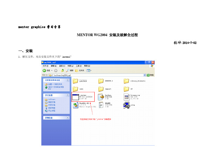
mentor graphics学习分享MENTOR WG2004 安装及破解全过程张冰2014-7-02一、安装1.解压文件,双击安装文件夹下的”_instmsi”2.选择“是”,然后出现安装的目录,选择“NEXT”后,会自动拷贝安装所需要的文件,稍等,到出现正式界面4.点击“Install Products”5.点击”Agree”6.按照下面的提示选择好Mentor软件安装文件所在的目录,以及想要安装到的目录,点击“Next”7.勾选第一项“Integreted Systems Design…”选择“NEXT“.8.选择常用的工具:“License Server”、“PCB Browser”、“Library Manager Design Capture”、“Design Capture”、“DesignView”、“Expedition PCB”,点击“Next”9.点击“Install”.10.安装过程中出现下面的界面,直接点击“OK”,继续安装11.安装进度条跑完100%后,出现下面的界面,点击“NEXT”12.选择安装的目录,此处默认是在前面第6步中选择的目录,一般不做修改,点击“NEXT”13. 点击“Skip”(无需点击NEXT ,安装界面自动消失)14. 点击“确定”15. 上一步完成后,软件会自动安装并注册相关文件,注意:不要关掉期间任何的DOS窗口及安装界面,只需等待1~2分钟。
等待安装结束,点击“Done”16. 点击“Exit”,退出安装程序二、破解1.打开安装文件下License文件夹,双击“MentorKG.exe”生成License文件,然后将生成的“License.txt”拷贝至C盘的Flexlm文件夹(如果没有此目录,则需手动新建)2.点击“开始菜单”→“所有程序”→“Mentor Graphics Licensing”→“Configure Licensing”3.点击“NEXT”4. 选择第③项“Define product license locations”,点击“Next”5.选择刚刚拷贝至C盘Flexlm文件夹下的License.TXT,选择“Next”5.点击“确定”,结束软件的破解安装至此,软件的安装及破解全部都已经完成,点击快捷方式“Design Capture”、“Expedition PCB”、“DesignView”,如果能够成功打开,则证明安装及破解成功(God bless you!)。
- 1、下载文档前请自行甄别文档内容的完整性,平台不提供额外的编辑、内容补充、找答案等附加服务。
- 2、"仅部分预览"的文档,不可在线预览部分如存在完整性等问题,可反馈申请退款(可完整预览的文档不适用该条件!)。
- 3、如文档侵犯您的权益,请联系客服反馈,我们会尽快为您处理(人工客服工作时间:9:00-18:30)。
Mentor EN2004 ( Board Station ) 中文简明教程---- ( 源自:http:/ )目录前言第一章: Board Station 架构与设计流程第二章:Design Manager界面介绍第三章:Librarian 工具的使用第四章: 设置布线规则及手动布线(Layout的使用)第五章:Fablink 的使用和出Gerber数据附录:Board Station环境变量的设定前言本教程将会介绍Mentor Graphics Board Station PCB Tool 整个架构及设计流程。
在第二章,介绍Board Station 的架构与流程。
从第三至第五章,实际设计一个简单的板子,从导入/创建库元件(Geometry)、摆放组件(Placement)、走线(Routing)与出 Gerber 制版数据。
1. 导入库文件(Resolve Geometry)2. 摆放元件(Placement)3. 布线(Routing)4. 出 Gerber 制版数据第一章: Board Station 架构与设计流程※名词解释:Board Architect: 线路图设计。
产生对象:comps、nets、tech、gates、pins、catalog、reuse。
Librarian: 提供零件库维护及建立新零件功能。
产生对象:geoms。
Layout: 提供摆放组件及绕线功能。
产生对象:traces。
Board Station RE: 提供更快速绕线、自动绕线、Hispeed 绕线功能。
产生对象:traces。
Fablink: 提供 Gerber Out、Gerber Check功能。
产生对象: drill_table、aperture_table、artwork。
如果你是由Board Architect(原理图编辑工具)开始设计,你可以编辑原理图,新增、修改元件(Component) 、连接网络(Net) 、定义可重复使用区域(Reuse Block)的属性以及设定Design Rules,如:线长、线宽、每个物件(trace, via, pin, plane fill...)之间的距离(spacing)与Hispeed Net Rule..等等。
如果你是从其它的原理图工具进入Board Station,那必须输出Mentor Board Station 格式的Netlist 与 Complist,至少必须输出这两个文字文件(ASCII file),然后将其转换成Board Station 的两个对象(nets & comps),再到Board Station 的Librarian Tool 将所需要的物理封装库(geometry)与板框,从公司零件库中,下载到自己的Project工作目录下,形成零件库对象geoms。
并检查所有的实体组件,都没有问题后,就可以进入到 Layout Tool 。
进入Layout 之后,你可以选择在Layout Tool 作手动或自动摆放元件(Manual/Auto Placement)以及半自动拉线的ADE Router,或是在Board Station RE Tool 环境下摆放元件、作全自动布线、并且可以设定Hispeed Rules 自动拉等长线及设定Differential Pairs 手动或自动布线等功能。
当所有的连接线(traces)都完成连接之后,就可以进入Fablink Tool,定义Gerber order、作分割Power层(或在Layout Tool完成亦可)、执行Gerber Check(MDV Tool) 、最后输出Gerber 值班数据。
第二章:Design Manager界面介绍鼠标左键点击开始 > 程序 > Mentor Graphics > Dmgr即可打开 Board Station 程序,进入Design Manager界面。
Design Manager 界面是用来管理Mentor Board Station 设计工具与工程文件的接口。
左边窗口是Tools Window,你安装的Tools 都会在此窗口出现,你可以按右键选Update Window 来重新排列图示。
右边窗口是工作路径下的文件夹,你可以按右键选View by Name ,依照档名来重新排列文件夹。
Lab 1 – 从DMGR产生comps与nets两个pcb对象: ( 需要数据: MGT_Library.rar(点击下载),解压缩至工作路径 C:/Home 路径下 )1. 新增数据夹,Add> Directory,输入: ADESIGN。
2. For BA USER:如果你使用的线路图编辑工具是Mentor 的Board Architect,请至路径"C:/Home/MGT_Library/BS_Quick_Start/ATEST_schematic"下,直接将所有档案,复制到你现在编辑的design 路径下(C:/Home/ADESIGN),并请跳过这个练习。
因为,于BA 作储存即会产生 comps & nets 对象。
For Orcad USER:载入其它线路图工具输出的 .CMP & .NET档案:1)、从下拉选单,选择MGC> Orcad to BS... 项目,再选择Create/Update Design。
2)、并依指示选择欲输入的CMP与NET档案,如下图。
第三章:Librarian 工具的使用1. 启动LIBRARIAN tool:在Design Manager中,点选Librarian图标,并双击Librarian 图标。
2. Librarian Options:选择 On a Design,再选到你所新增的design资料夹ADESIGN,按OK;接着选择 Stand PCB,按OK,Option 不选,再按OK;如下图。
3. 进入librarian:进入librarian后,会有一个讯息窗口,记载着进入librarian的过程中,程序执行的讯息。
请按着中间键,由左向右画一 (stroke 456),执行画图命令 (Stroke Command)来关闭讯息窗口。
4. 建立板框 Board Geometry:(1) 从下拉选单(Pull Down Menu),选Geometries > Create_Geometry > Board...并填入板框讯息,如下图所示,再按 OK。
(2) 执行 Setup > Edit Layer… (或 stroke 36987),即会出现层面设定窗口,点选BOARD_OUTLINE,按OK。
在工作窗口按鼠标右键 [Shapes] > Add Line > Add Line : , 依照下列座标点完成 Board_Outline 范围:(0, 0) → (0.25, -0.25) → (2.475, -0.25) → (2.725, 0) → (2.725, 3) (2.475, 3.25) → (0.25,3.25) → (0, 3) → (0, 0)(3) 建立 Placement Outline,请按右边工具列中的PLACE_OUTLINE,选择Automatic,输入0.04的安全间距,按OK。
(4) 建立 Routing Outline,请按右边工具列中的ROUTING_OUTLINE图示,选择Automatic,输入0.04的安全间距,按OK。
5. 建立Through Hole Via:从下拉选单,选取Geometries > Create_Geometry > Thruhole Via…,并填入以下讯息,建立一个 Through Hole Via – VIA_25_13。
6. 建立Through Hole Pin:从下拉选单,选取Geometries > Create_Geometry > Thruhole Pin…,并填入以下讯息,建立一个 Through Hole Pin – P30_50。
7. 建立 Surface Pin:从下拉选单,选取Geometries > Create_Geometry > Surface Pin…,并填入以下讯息,建立一个 Surface Pin – S51X55。
8. 建立 Component:从下拉选单,选Geometries > Create_Geometry > Component…,并填入以下讯息,建立一个 Component –CC0805。
下拉选单,Setup > Grid… , 即出现设定格点对话窗,设定如下 X Increment = 0.1 , Display Interval = 1,按 OK。
在工作列中,点选 Add Pins Icon , 确定Numeric=1, Increment=1,将 Pin 放在坐标 Pin1 (0, 0); Pin2 (74.8, 0); 你可以用 coo 命令来订定坐标,如 “coo 0 0"与“coo 74.8 0"加完两个pin之后,用笔势命令,stroke 654,取消Add Pins 的命令。
接下来,点选右边功能列PLACE_OUTLINE 图标点选 Both Layers,加入组件的外框。
这时候,左下角会出现一个命令列,并且在等待你画一个封闭的组件 DRC 范围,参考坐标如下。
(-35.5, -37.5) → (110.2, -37.5) → (110.2, 37.5) → (-35.5, 37.5) → (-35.5, -37.5)*设定线宽:点击工具列中的SHAPES图标,后点击SETUP SHAPES 图标,来设定线段格式、线宽、编辑层面等。
*画上Placement Body Outline:设定当前可编辑层在 Silkscreen Layer,执行[Shapes] > Add Line > Add Line :,沿着元件画 Body Outline。
*摆放Reference Designator 的位置:点击工具列中的TEXT图标,后点击ADD REF图标,摆放Reference Designator 的位置。
*Check All Geometries:下拉选单Check > Geometry > Active Geometry …9. 设定Design Rule:Physical Layer 在下拉选单,Setup Design Rules > Physical Layers… , 即出现 Setup Physical Layers 对话窗 , 完成如下图所示 :10. 储存Geometry:File > Save > Design All,并关闭 Librarian。