dw5600e说明书
戴尔在线机架式UPS 5600W 用户指南说明书
Dell t在线机架式UPS5600W用户指南Dell5600R OL HV-US,Dell5600R OL HVK812N w w w.d e l l.c o m|s u p p o r t.d e l l.c o m注意和警告注意:“注意”表示可帮助您更好使用本产品的重要信息。
小心:“小心”表示潜在危险情况,如果不加以避免,可能导致轻度或中度伤害,或财产损失事故。
警告:“警告”表示潜在危险情况,如果不加以避免,可能会导致死亡或伤害。
危险:“危险”表示紧急危险情况,如果不加以避免,将导致死亡或严重的伤害。
危险:遵守下列须知有助于防止紧急危险情况,其若不加以避免,将导致死亡或严重的伤害:S本UPS包含危险致命的电压。
所有维修和服务都只能由经过授权的维修人员进行。
UPS中没有用户可自行维修的部件。
小心:此为A级产品,在生活环境中,该产品可能会造成无线电干扰。
在这种情况下,可能需要用户对干扰采取切实可行的措施。
本文档所含信息如有更改,恕不另行通知。
©2009–2013Dell Inc.保留所有权利。
未经Dell Inc.书面允许,严禁以任何形式进行复制。
本文中使用的商标:Dell和DELL徽标是Dell Inc.的商标;Greenlee是Greenlee Textron的注册商标;National Electrical Code及NEC是National Fire Protection Association,Inc.的注册商标;Phillips是Phillips Screw Company的注册商标。
本文件中可能会使用其它商标或商业名称来指称拥有该商标或名称权利的实体或其产品。
Dell Inc.对不属于自己的商标和商品名称,不拥有任何权利。
2013年7月•1642018983目录1简介......................................................查找信息8 2安全警告3安装检查设备11............................................................................................................机箱拆包12....................................................UPS后面板14UPS前面板15..........................................................................................................机架安装16......................................................安装EBM23安装UPS23................................................................................................安装远程应急电源关闭24UPS输入硬连线26..................................................................................................UPS初始启动30 4操作UPS启动和关机31..................................................................................................启动UPS31...........................................通过电池启动UPS32..................................................UPS关机32..................................................控制面板功能33......................................................变更语言343目录|显示功能34........................................................................................................开机屏幕34..................................................屏幕锁定35..................................................UPS状态35..................................................事件日志38......................................................测量39..................................................控制屏幕40......................................................标识41......................................................设置41......................................UPS在各种模式之间的转换46.................................从“正常”转为“旁路”模式46.................................从“旁路”转为“正常”模式46撷取事件日志46................................................................................................过载情况下的表现47..............................................配置输出开关控制48.................................通过显示屏控制输出开关控制48...........................................配置自动输出延迟49.................................配置电池模式后自动关闭延迟50配置电池设置51.............................................................................................为配置UPS EBM51...........................................运行自动电池自检52配置自动电池自检52.............................................................................................配置自动重启52 5其它UPS特性........................................RS-232和USB通讯端口53Dell网络管理卡(可选)55...................................................................................Dell UPS管理软件564|目录6UPS维护................................................UPS和电池保养57......................................................运输UPS57...............................................存放UPS和电池59..................................................何时更换电池59..................................................进行电池自检60.................................................更新UPS固件607规格8故障排除................................................获取警报和情况65..............................................UPS状态菜单65...............................................事件日志菜单66................................................典型警报与状况66....................................................使警报消声715目录|1简介Dell t在线机架式不间断电源(UPS)可保护您敏感的电子设备免受基本电力问题的损害,如停电、电压突降、电压浪涌、电压不足和传输线干扰。
5600(V5.0)高精密数字温度计使用说明书

3
3. 输入接线及注意事项
Thermocouple PT D or Resistor mV or mA Thermocouple wire Constant temperature bath Copper lugs Copper wire Copper wire × 4 Thermocouple wire Copper wire Copper wire Thermocouple Pt100
]=1、热电偶采用 _ ]值、FILt [ ]值有关。 _ ]=1、FILt[
2) 测量条件:仪表在稳定的温湿度环境下放置 1h、开机时间 5min 后,S_rAtE[ MAN 补偿方式,输入 80%FS 稳定的信号。
_ ]设置。 _
(4) 采样速率:采样速率由菜单参数 S_rAtE[
输入信号 热电偶 (INT/EXT 补偿) 其他输入信号
4. 显示屏
1.数学功能 5.保持 2.低电压
4.整体修正或 传感器修正
3.自动关机 6.单位
7.主显示
8.热电阻热 电偶分度号
9.热电偶参 考端温度补 偿方式
10.下限上 限报警
(1) REL/MAX/MIN/AVG/P-P/SN:数学功能,分别代表:相对值、最大值、最小值、平均 值、峰-峰值、标准差和采样数。其中标准差和采样数都用“SN”作为标识; (2) LOWBAT:当电池电压低时显示此标识; (3) AUTOOFF:当设置自动关机时显示此标识; (4) –T2/OFFSET:带有整体修正时的示值用“-T2”标识,而当菜单中传感器平移修正值 OFFSEt≠0 时,显示 “OFFSET” 标识; (5) HOLD:显示保持; (6) mVAΩ℃℉K:测量单位; (7) 6 位 LCD 显示:测量值或提示信息; (8) Pt100/Pt1000/Cu50/Cu100/K/J/T/S/R/E/N/B:热电阻和热电偶分度号。而Ω档、mV 档、mA 档没有“分度号” ,仅以其显示单位Ω、mV、mA 进行标识; (9) INT/EXT/MAN:热电偶参考端的补偿方式; (10) LOAL/HIAL:分别表示下限报警、上限报警。
【首晒】经典最弥久:CASIO 卡西欧 G-SHOCK DW5600E-1V 男款经典腕表
DW5600是卡西欧(CASIO)第一块真正意义上的G-SHOCK,虽然不是第一块命名为G-SHOCK的表,但G-SHOCK 的成名由此而来,连第一块BABY-G也是由它的衍生型-DW500而来。
作为历史上销量最好的G-SHOCK款色,它以最初型号的款色从来未被从G-SHOCK的名单上剔除过。
小学的时候正是电子表流行的年代,从路边的小卖部到商场的柜台都能见到各种新奇样式的电子表,当时新鲜的功能无非是背光,秒表,倒计时,还有带计算机功能的,升初中的时候我终于有了第一块表5600,当时对于这块表背后的文化啊什么的一概不知道,就知道这只表有背光,爸妈给我买这块表的原因很简单--放学后别贪玩按时回家。
就这样5600从初中一直陪伴我到大学,念大学的时候有了第一块手机,手机有时间显示,看时间设定闹铃又方便,渐渐地5600就进入了“箱底”。
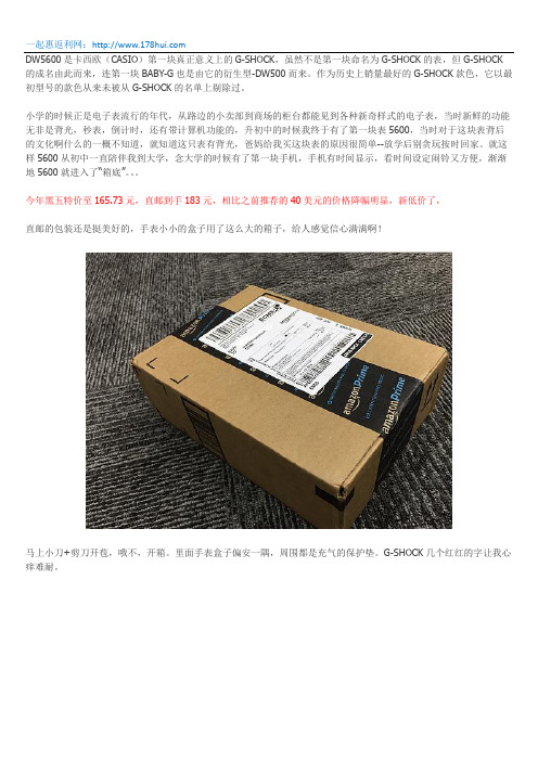
今年黑五特价至165.73元,直邮到手183元,相比之前推荐的40美元的价格降幅明显,新低价了,直邮的包装还是挺美好的,手表小小的盒子用了这么大的箱子,给人感觉信心满满啊!马上小刀+剪刀开苞,哦不,开箱。
里面手表盒子偏安一隅,周围都是充气的保护垫。
G-SHOCK几个红红的字让我心痒难耐。
取出小盒子,尼玛说好的小铁盒呢?怎么尼玛就是一破纸盒子啊~~~~马上上网搜索晒物,原来这个价位就只是这么一个纸盒子。
好吧,继续开苞,哦不,开箱~打开盒子,就是这么一个小支架映入眼帘:隐约中还有膜~~犹抱琵琶半遮面,朦(chu)胧(nv)美(mo),我喜欢掀起了你的盖头来,让我来看看你的脸~~呆萌小方脸跃然而出~~从这里可以看出,做为一款入门级的G-shock ,没有电没有波,但是整体做工还是可以的,对于我这么个大大咧咧的人来说,这个质感已经让我很满足了。
这里面就是所有的东西了,底座,说明书,手表和国际联保卡,里面有广州,北京,上海三家联保单位哦~按理说应该也能享受国际联保一年~说明书非常薄,我也懒得看,有需要说明书的,大家可以上casio 的中国官网下载,按机芯型号搜索,机芯型号就是3229~非常简单,但是就是纯朴,耐用~~你看那200m 防水~左上角的A 键跟其他3个略微不同,是有一点凹陷的,必须用指甲戳才能有反应,这正是设计的细节,因为A 键就是用来调时间的,做的下陷一点,不容易误操作。
5600SE下风过滤器系统操作指南说明书

Master Programming Mode Flow Chart for Single Backwash ValvesWith Time of Day display set to 12:01 P.M., push and hold both the Set Up and Set Down buttons for 5 /Metric Display FormatExample: US display Format [U--1]Regeneration TypeExample: Meter Delayed Regeneration [7--3]Treated Water CapacityExample: 1,000 gallons/liters/cubic meters [1000]Regeneration TimeExample: Regenerate as needed at 2:00 A.M. [2:00]Regeneration Day OverrideExample: Regenerate at a minimum frequency of 3 days [A--3]Regeneration Cycle Step #1Example: 10 minute step time [1-10]Regeneration Cycle Step #2Example: 60 minute step time [2-60]Regeneration Cycle Step #3Example: 10 minute step time [3-10]Regeneration Cycle Step #4Example: 12 minute step time [4-12]Regeneration Cycle Step #5Example: Step 5 Cancelled [5OFF]Flow Meter SizeExample: 5600SE 3/4" Turbine Flow Meter [F133]Valve TypeExample: 5600SE Valve [o--1]Line FrequencyExample: 60 Hz Line Frequency [LF60]Master Programming Mode is exited,Normal Operation is resumedNOTE:1.Set Time of Day display to 12:01 P.M.2.Push and hold both the Set Up and Set Down buttons for 5 seconds.3.Push Extra Cycle button once per display until all displays are viewed and Normal Operation is resumed.4.Option setting displays may be changed as required by pushing either the Set Up or Set Down button.5.Depending on current valve programming certain displays will not be able to be viewed or set.6.Reference programming instructions for complete list of available settings.Page 1Master Programming Mode Flow Chart for Double Backwash ValvesWith Time of Day display set to 12:01 P.M., push and hold both the Set Up and Set Down buttons for 5 /Metric Display FormatExample: US display Format [U--1]Regeneration TypeExample: Meter Delayed Regeneration [7--3]Treated Water CapacityExample: 1,000 gallons/liters/cubic meters [1000]Regeneration TimeExample: Regenerate as needed at 2:00 A.M. [2:00]Regeneration Day OverrideExample: Regenerate at a minimum frequency of 3 days [A--3]Regeneration Cycle Step #1Example: 10 minute step time [1-10]Regeneration Cycle Step #2Example: 60 minute step time [2-60]Regeneration Cycle Step #3Example: 10 minute step time [3-10]Regeneration Cycle Step #4Example: 10 minute step time [4-10]Regeneration Cycle Step #5Example: 12 minute step time [5-12]Regeneration Cycle Step #6Example: Step 6 Cancelled [6OFF]Flow Meter SizeExample: 5600SE 3/4" Turbine Flow Meter [F133]Valve TypeExample: 5600SE Valve [o--1]Line FrequencyExample: 60 Hz Line Frequency [LF60]Master Programming Mode is exited,Normal Operation is resumedNOTE:1.Set Time of Day display to 12:01 P.M.2.Push and hold both the Set Up and Set Down buttons for 5 seconds.3.Push Extra Cycle button once per display until all displays are viewed and Normal Operation is resumed.4.Option setting displays may be changed as required by pushing either the Set Up or Set Down button.5.Depending on current valve programming certain displays will not be able to be viewed or set.6.Reference programming instructions for complete list of available settings.Page 2Master Programming ModeSet Up buttonExtra Cycle button Set Down buttonWhen the Master Programming Mode is entered, all available option setting displays may be viewed and set as needed. Depending on current option settings, some displays cannot be viewed or set.Entering Master Programming ModeSet the Time Of Day display to 12:01 P.M. Push and hold the Set Up and Set Down buttons together until the Program Dot turns on (about 5 seconds). Depending on current option settings, some displays cannot be viewed or set.Exiting Master Programming ModePush the Extra Cycle button once per display until all are viewed. The Program Mode is exited and normal operation resumes. Resetting Permanent Programming MemoryPush and hold the Set Up and Set Down buttons for 25 seconds or until the Time Of Day display resets to 12:00 P.M. All option settings reset to default values. Control programming must be reset as necessary./Metric Display Format (U)Push the Extra Cycle button. This display is used to set the desired display format. This option setting is identified by the "U"in the first digit. The possible settings are:US Format uses gallons for volume with a 12-hour timekeeping format. Regeneration timing in minutes.Example:[U - - I]Metric Format uses liters for volume and a 24-hour timekeeping format. Regeneration timing in tenths of minutes. Use the Set Up and Set Down buttons to adjust this value.Example:[U - - 2]Cubic Meter Format uses cubic meters for volume and a 24-hour timekeeping format. Regeneration timing in tenths of minutes. Use the Set Up and Set Down buttons to adjust this value.Example:[U - - 4]Page 3Master Programming Mode (Cont’d.)2.Regeneration Type (7)Push the Extra Cycle button. Use this display to set the Regeneration Type. This option setting is identified by the number "7"in the first digit. There are three possible settings:Timeclock DelayedThe control determines the day that a regeneration is required by the Regeneration Day Override setting (A). Once this day is reached, a regeneration cycle starts at the set Regeneration Time.Example:[7 - - I]Meter ImmediateThe control determines that regeneration is required when the available volume of treated water drops to zero. Regeneration begins immediately.Example:[7 - - 2] (This setting is typically used by the 9000SE)Meter DelayedThe control determines that a regeneration is required when the available volume of treated water drops to zero. Regeneration begins immediately at the set Regeneration Time. Use the Set Up and Set Down buttons to adjust this value.Example:[7 - - 3]3.Treated Water Capacity (No Display Code)Push the Extra Cycle button. Use this display to set the amount of water (gallons/liters/cubic meters) that can be treated by the unit before a regeneration cycle is required. With Meter Delayed Regeneration Type set, it is necessary for the programmer to determine a reserve capacity and subtract that value from the calculated full capacity of the unit. This display cannot be viewed with Timeclock Regeneration Type set. Use the Set Up and Set Down buttons to adjust this value.Example:Regenerate every 700 gallons/liters/cubic meters —[7 0 0]4.Regeneration Time (Clock Display Without a Flashing Colon)Push the Extra Cycle button. The next display that appears is the option setting for Regeneration Time. It is identified by a clock display without a flashing colon. Set the desired time of day that a regeneration may occur. This display cannot be viewed with Meter Immediate Regeneration Type set. Use the Set Up and Set Down buttons to adjust this value.Example: 2 o'clock A.M. Regeneration Time —[2: 0 0] (A.M. Indicator Dot On)5.Regeneration Day Override (A)Push the Extra Cycle button. Use this display to set the maximum amount of time (in days) the unit can be in service withouta regeneration. This option setting is identified by the letter "A" in the first digit.–With Timeclock or Meter Delayed Regeneration Types selected, regeneration begins at the set Regeneration Time.–With Meter Immediate Regeneration Type selected, regeneration begins at the same time of day that the last regeneration cycle was initiated. An OFF setting cancels this feature with all regeneration types except Timeclock Regeneration were it must be used. Use the Set Up and Set Down buttons to adjust this value.Example:Override every 7 days — [A - - 7]Cancel setting — [A O F F] (Meter Immediate or Delayed Regeneration Types Only)Page 4Master Programming Mode (Cont’d.)6.Regeneration Cycle Step Programming (1) (2) (3) (4) (5) (6)Push the Extra Cycle button. The next 2–6 displays that appear are part of a series of option settings used to program the Regeneration Cycle. Each display is used to set in minutes (or tenths of minutes - Metric). A step # turns on for theregeneration cycle step being programmed.–Skip regeneration steps by setting the display to 0–End a regeneration cycle by setting the step # after the last active step to OFF, as shown below:Example:Regeneration Cycle Step #1, 8 minutes —[I - - 8](US Format)Regeneration Cycle Step #3, skipped — [3 - - 0] (US Format)Regeneration Cycle Step #4, 8.5 minutes —[4 - 8.5] (Both Metric Formats)Regeneration Cycle Step #4, cancelled —[4 O F F] (All Formats)Push the Extra Cycle button once per display to advance through Regeneration Cycle Step Programming.Proper softener operation requires the calculation of a brine tank refill time:(Pounds of Salt Used per Regeneration Cycle ÷ 3) ÷ BLFC Size = Refill Time in MinutesExample:(10 lbs salt ÷ 3) ÷ 0.25 gpm = 13.3 minute refill(Consult valve service manual for actual step location)Use the Set Up and Set Down buttons to adjust this value.7.Flow Meter Size (F)Push the Extra Cycle button. The the next display sets the flowmeter size. Use this display to set the proper amount of pulses generated by the flow meter for each gallon or liter of water flow. This setting cannot be viewed with Timeclock Regeneration Type selected.Example:[F I 2 6] 3/4” Turbine Flow Meter used with the 2510SE (US Format)Example:[F 3 3.2] 3/4” Turbine Flow Meter used with the 2510SE (Metric Format)Example:[F 1 3 2]3/4” Turbine Flow Meter used with the TwinFlo100E (US Format)Example:[F 3 4.9] 3/4” Turbine Flow Meter used with the TwinFlo100E (Metric Format)Example:[F 1 3 3]3/4” Turbine Flow Meter used with the 5600SE or 9000SE (US Format)Example:[F 3 5.1] 3/4” Turbine Flow Meter used with the 5600SE or 9000SE (Metric Format)Example:[F - 2 0] 3/4” Paddle Wheel Flow Meter (US Format)Example:[F - 5.3] 3/4” Paddle Wheel Flow Meter (Metric Format)Example:[F - - 8] 1.0” Paddle Wheel Flow Meter (US Format)Example:[F - 2.1] 1.0” Paddle Wheel Flow Meter (Metric Format)Use the Set Up and Set Down buttons to adjust this value.8.Valve Type (o)Push the Extra Cycle button. Use this display to set the type of valve used with the control. This option setting is identified by the letter "o" in the first digit. When #2 is selected, the current Tank # in Service must be entered in the next display.Example:[o - - I] 2510SE, 2750SE or 5600SE Valve Operation.Example:[o - - 2]9000SE or TwinFlo100E Valve Operation.Example:[o - U I] Unit #1 Tank in Service. (Viewed with #2 set only)Use the Set Up and Set Down buttons to adjust this value.Page 5Master Programming Mode (Cont’d.)9.Line Frequency (LF)Push the Extra Cycle button. Use this display to set the frequency of the power applied to the control. When properly set, all timekeeping functions remain accurate. This option setting is identified by the letters "LF" in the first two digits. There are two possible selections.Example:[L F 5 0] 50 Hz Line Frequency Operation.Example:[L F 6 0] 60 Hz Line Frequency Operation.Use the Set Up and Set Down buttons to adjust this value.Push the Extra Cycle button once more to exit this programming mode.Page 6P/N 41674 Rev. A。
5600中文调试说明书

5600调试说明书1Dial Selection数字面表显示数字面表显示,批处理百分比显示。
2Power Connection供电5600可以接直流或交流24V供电,不要将220V接入设备,会烧坏设备,为了减少电流噪声的影响,电源供电线和数据线要独立走线。
具体连接请按英文说明书第一页第二个图连接3Compatible Sensor Wiring探头的连接我公司的流量探头有两种输出信号:一种为正弦信号(如 515,525,2517等),另一种为方波信号(2000,2507等),探头的连接请按英文说明书第一页第三个图连接。
为了减少电流噪声的影响,电源供电线和数据线要独立走线。
4Batch Contact Wiring 批处理连接(5600与电磁阀的连接)连在背面板上的Batch端,它就相当于一个开关,具体连接请按英文说明书第一页第四个图连接。
5Remote Control Wiring 远程控制开关实现远程控制功能,与背面板的Remote的连接,远程连线最大不要超过30米,具体连接请按英文说明书第二页第一个图连接6End of Batch/Counter Pulse Output Wiring批处理和计数连接实现脉冲计数功能,与背面板的CNT/EOB Output连接,具体连接请按英文说明书第二页第二个图连接。
图A表示计数器的连接;图B表示二个5600的连接(即End of Batch功能)7Option Contact Wiring OptionsOption Contact相当于另一个控制开关,A图表示Two Stage Shutdown (两个阀门比较功能),图在第二页的7AB 图表示无流量告警信号或过流告警信号的接法,图在第二页的7B8Current Output Wiring OptionsA图表示4~20mA的接法,建议还要接一个保险,在第二页的8AB图表示电动阀的接法,在第二页的8B调表步骤:进入菜单:因为要按ENTER键,所以不要在5600的第一个显示项中进入校准菜单,在后面几个显示菜单中再按下面步骤进入Cal和Options菜单STEP 1按住ENTER键:2秒后进入校准程序(CAL),5秒后进入选项程序(OPTIONS) STEP 2密码为 (上上上下),在输入密码后,显示第一个选择项STEP 3用上下键选择菜单STEP 4按右键来选择需要的项目,被修改的项目会闪烁STEP 5对闪烁的项目按上,下键来修改此项目,按右键选择旁边需修改的项目STEP 6按ENTER键储存修改后会自动返回STEP3STEP 7同时按下上下键返回正常状态.一 AUTO CAL的使用使用AUTO CAL时,要确定流出液体的体积(可用灌或桶),由于AUTO CAL 要计算时间,所以泵和AUTO CAL要同时开动或停止,这样计出来的时间会较准,操作过程为在Auto Calibrate <Enter> to Start 菜单下,按下Enter,开始计时,在Auto Calibrate <Enter> to Stop菜单下,按下Enter,停止计时,在Volume 菜单中,输入测量值。
安讯士5600系列机械热探测器技术规格说明书

5600 SeriesMechanical Heat DetectorsDN-6931:A1 • I-304GENERALSystem Sensor’s 5600 Series mechanical heat detectors offerproperty protection against fire and for non-life-safety installa-tions, where smoke detectors are inappropriate.Multiple configurations. The 5600 Series offers a full line ofconfigurations to accommodate a broad range of applications.Bo th single- and dual-circuit mo dels are o ffered, each avail-able fo r lo w- and high-temperature ratings with either fixed-temperature o r c o mbinati o n fixed-temperature/rate-o f-rise(ROR) activation. The ROR element of the fixed/ROR modelsis restorable, to accommodate field-testing the unit.Installation flexibility. To satisfy a variety of installations, the5600 Series easily mounts to single-gang and octagonal back-bo xes. These mo dels also acco mmo date 4" (101.6 mm)square backboxes when used with a plaster ring. The mount-ing bracket is reversible to allow for flush- and surface-mount backbox installations.Visual identification. The 5600 Series provides clear mark-ings on the exterior of the unit to ensure that the proper detec-to r is being used. Alphanumeric characters identify the activatio n metho d, as well as the temperature rating, in degrees Fahrenheit and Celsius. Fixed temperature mo dels are identified “FX”, while co mbinatio n fixed/rate-o f-rise units are marked “FX/ROR”. The 5600 Series also provides a col-lecto r as a po st-activatio n indicato r. Once the detecto r has been activated, the collector drops from the unit to allow easy identification of the specific unit in alarm.FEATURES•Multiple configurations available:–Fixed-temperature (no n-resettable) o r co mbinatio n fixed (non-resettable)/rate-of-rise (self-restoring).–Low-temperature and high-temperature ratings.–Single-circuit and dual-circuit.•Easy-to-read alphanumeric identificatio n o f detecto r type and temperature rating.•External collector provides visual indication of activation.•Reversible mo unting bracket fo r flush- and surface-mo unt installations.•Flexible mounting capabilities: single-gang, 3.5" or 4" octag-onal, 4" (101.6 mm) square with plaster ring.•Easy-to-use terminal screws provide a more positive wiring connection.•Low-profile design to coordinate with room aesthetics.AGENCY LISTINGS AND APPROVALS These listings and approvals apply to the modules specified in this document. In some cases, certain modules or applications may not be listed by certain approval agencies, or listing may be in process. Consult factory for latest listing status.•UL Listed: S2101•ULC Listed: S2101 (all with “A” suffix)•MEA: 199-03-E•CSFM: 7270-1209:227, 7270-1653:167•FM Approved SPECIFICATIONSPHYSICAL SPECIFICATIONSMaximum installation temperature:For models 5601P, 5603, 5621, 5623: 100°F (38°C).For models 5602, 5604, 5622, 5624: 150°F (65.6°C).Alarm temperature:For models 5601P, 5603, 5621, 5623: 135°F (57°C).For models 5602, 5604, 5622, 5624: 194°F (90°C).Rate of Rise Threshold: 15°F (8.3°C) per minute (mo dels 5601, 5602, 5621, 5622 only).Operating Humidity Range: 5% to 95% RH noncondensing. Input Terminals: non-polarized, accept 14 to 22 AWG (2.0 to 0.33 mm²).Dimensions: diameter with mounting bracket: 4.57" (116 mm); height with mounting bracket: 1.69" (43 mm).Weight: 6 oz. (170 grams).Mounting Options: 3.5" (88.9 mm) o ctago nal backbo x; 4" (101.6 mm) o ctago nal backbo x; single-gang backbo x; 4" (101.6 mm) square backbo x with a square-to-ro und plaster ring.ELECTRICAL SPECIFICATIONSMechanical heat detecto r shall be a System Senso r 5600 Series model number ______, Listed to Underwriters Labora-tories UL 521 for Heat Detectors for Fire Protective Signaling Systems. The detector shall be either a single-circuit or a dual-circuit type, normally open. The detector shall be rated for acti-vation at either 135°F (57°C) or 194°F (90°C), and shall acti-vate by means o f a fixed-temperature thermal senso r, o r a c mbinati n fixed-temperature/rate-f-rise thermal sens r. The rate-o f-rise element shall be activated by a rapid rise in temperature, appro ximately 15°F (8.3°C) per minute. The detector shall include a reversible mounting bracket for mount-Operating Voltage Contact Ratings (resistive)6 - 125 VAC 3.0 A6 - 28 VDC 1.0 A125 VDC0.3 A250 VDC0.1 A6931pho1.jpgDN-6931:A1 • 2/9/10 — Page 1 of 2Page 2 of 2 — DN-6931:A1 • 2/9/10©2010 by Honeywell International Inc. All rights reserved. Unauthorized use of this document is strictly prohibited.This document is not intended to be used for installation purposes. We try to keep our product information up-to-date and accurate. We cannot cover all specific applications or anticipate all requirements.All specifications are subject to change without notice.For more information, contact Notifier. Phone: (203) 484-7161, FAX: (203) 484-7118.ing to 3.5-inch (88.9 mm) octagonal, 4-inch (101.6 mm) octag-o nal, single gang, and 4-inch (101.6 mm) square backboxes with a square-to -ro und plaster ring. Wiring co nnectio ns shall be made by means of SEMS screws that shall accommodate 14 – 22 AWG wire. The detecto r shall co ntain alphanumeric markings on the exterior of the housing to identify its tempera-ture rating and activation method. The rate-of-rise element of co mbinatio n fixed-temperature/rate-o f-rise mo dels shall be restorable, to allow for field-testing. The detectors shall include an external collector that shall drop upon activation to identify the unit in alarm.ORDERING INFORMATIONWIRING DIAGRAMSModel*IdentificationMethod on ExteriorCircuit TemperatureRatingActivationUL Protected Spacing,10’ (3.048 m) Ceiling*5601P None Single 135°F (57°C)Fixed-Temperature/Rate-of-Rise 50 ft. x 50 ft. (15.24 m x 15.24 m)5602Lettering Single 194°F (90°C)Fixed-Temperature/Rate-of-Rise 50 ft. x 50 ft. (15.24 m x 15.24 m)5603Lettering Single 135°F (57°C)Fixed-Temperature 25 ft. x 25 ft. (7.62 m x 7.62 m)5604Lettering Single 194°F (90°C)Fixed-Temperature 25 ft. x 25 ft. (7.62 m x 7.62 m)5621Lettering Dual 135°F (57°C)Fixed-Temperature/Rate-of-Rise 50 ft. x 50 ft. (15.24 m x 15.24 m)5622Lettering Dual 194°F (90°C)Fixed-Temperature/Rate-of-Rise 50 ft. x 50 ft. (15.24 m x 15.24 m)5623Lettering Dual 135°F (57°C)Fixed-Temperature 25 ft. x 25 ft. (7.62 m x 7.62 m)5624Lettering Dual 194°F (90°C)Fixed-Temperature 25 ft. x 25 ft. (7.62 m x 7.62 m)NOTE: Refer to NFPA 72 guidelines for spacing reductions when ceiling heights exceed 10 feet (3.048 m).* Add an “A” to part number for ULC model .Single-Circuit ModelsDual-Circuit Models6931wir1.wmf6931wir2.wmf。
5600 系列机械式热探测器安装手册说明书

Before InstallingThis detector must be installed in compliance with the con-trol panel installation manual and meet the requirements of NFPA 72, and/or the local authority having jurisdiction. Read this manual carefully before using the detector. This manual should be left with the owner/user of this equip-ment.General DescriptionThe 5600 series mechanical heat detector is intended for use in property protection applications, or for non-life-safety installations where smoke detection is not practi-cal or appropriate.in lieu of, or in addition to mechanical heat detectors. The 5600 series consists of both single- and dual-circuit heat detectors featuring fixed temperature thermal sensors or combination fixed temperature/rate-of-rise sensors, with temperature ratings of 135ºF (57ºC) or 194ºF (90ºC).Markings on the exterior of the detector indicate the spe-cific activation method and temperature rating. All models are identified as either 135ºF/57ºC or 194ºF/90ºC. Models equipped with combination fixed temperature/rate-of-rise sensors are marked FX/ROR. Fixed temperature only mod-els are marked FX.NOTE: Refer to NFPA72 guidelines for spacing reductions when ceiling heights exceed 10 feet.Non-Resettable Fixed Temperature SensorThe fixed temperature element reacts to heat by respond-ing to a specific temperature setting (135ºF or 194ºF). The detection method is based on the spring action of a metal contact, held to the metal chamber by a fusible alloy. When the temperature reaches the alloy’s melting point, the metal contact will depress the diaphragm, causing the electrical contact to close the circuit. The circular external heat collector is released from the detector to visually indi-cate that the detector has been activated.NOTE: 5600 series Fixed T emperature models (5603, 5604, 5623, and 5624) are non-resettable, and cannot be tested.Self-Restoring Rate-of-Rise (ROR) SensorThe rate-of-rise element responds to a rapid rise of temper-ature, approximately 15ºF (8.3ºC) per minute. As the tem-perature rises, the air within the sealed chamber expands. Should the chamber air expand faster than it can escape through the calibrated vent, the diaphragm is depressed, and the electrical contact closes the circuit.NOTE: Only the ROR element of 5600 series combination fixed temperature/ROR models (5601, 5602, 5621, and 5622) are self-restoring, and may be tested using a hair dryer or heat gun. When testing the ROR element, to pre-vent the activation of the fixed temperature element, the heat source must not exceed the fixed temperature rating of the detector.Mounting BracketAll 5600 series detectors are equipped with a mounting bracket that includes mounting slots to accommodate single-gang, 31⁄2″ octagonal, and 4″ octagonal electrical boxes, as well as 4″ square boxes equipped with a plas-ter ring (Figure 1). The mounting bracket is reversible to accommodate flush-mount and surface–mount installa-tions (Figure 2).INSTALLATION AND MAINTENANCE INSTRUCTIONS3825 Ohio Avenue, St. Charles, Illinois 601741-800-SENSOR2, FAX: 630-377-64955600 SeriesMechanical Heat DetectorSingle Circuit: 5601, 5602, 5603, 5604Dual Circuit: 5621, 5622, 5623, 5624Table 1. 5600 Series Mechanical Heat Detectors Figure 1. Bracket Mounting LocationsA= 31⁄2″ Octagonal boxB= 4″ Octagonal box C= Single gang box and 4″ square with plaster ringD= Directly to Wall/CeilingS T R IP G A U G EBCDDAABCModel No.CircuitTemperatureRatingThermal SensorUL Maximum Spacing(10-foot ceiling)5601Single 135ºF (57ºC)Fixed T emperature/Rate of Rise 50-feet x 50-feet 5602Single 194ºF (90ºC)Fixed T emperature/Rate of Rise 50-feet x 50-feet 5603Single 135ºF (57ºC)Fixed T emperature 25-feet x 25-feet 5604Single 194ºF (90ºC)Fixed T emperature 25-feet x 25-feet 5621Dual 135ºF (57ºC)Fixed T emperature/Rate of Rise 50-feet x 50-feet 5622Dual 194ºF (90ºC)Fixed T emperature/Rate of Rise 50-feet x 50-feet5623Dual 135ºF (57ºC)Fixed T emperature 25-feet x 25-feet 5624Dual194ºF (90ºC)Fixed T emperature25-feet x 25-feetWiring Installation GuidelinesAll wiring must be installed in compliance with the National Electrical Code, applicable state and local codes, and any special requirements of the local Authority Having Jurisdiction. Proper wire gauges should be used. The conductors used to connect heat detectors to the alarm control panel and accessory devices should be color-coded to reduce the likelihood of wiring errors. Improper connec-tions can prevent a system from responding properly in the event of a fire.The non-polarized screw terminals on the back of the detector will accept 14–22 A WG wire. For best system performance, all wiring should be installed in separate grounded conduit; do not mix fire alarm system wiring in the same conduit as any other electrical wiring. T wisted pair may be used to provide additional protection against extraneous electrical interference.Wire connections are made by stripping approximately 1⁄4″ of the insulation from the end of the feed wire, inserting it into the proper base terminal, and tightening the screw to secure the wire in place.InstallationRemove power from the alarm control unit or initiating device circuits before installing detectors.1. Detach the detector from the mounting bracket byrotating the detector 1⁄4 turn counter-clockwise.2. Orient the mounting bracket properly for either aflush- or surface-mount installation (Figure 2).3. Select the pair of mounting holes suitable for the junc- tion box, (figure 1) and secure the bracket to the box.4. Connect the wires to the detector per Figure 3 orFigure 4, as applicable.5. Place the detector onto the mounting bracket by rotat- ing clockwise. The detector will lock into place with a “click”.6. After all detectors have been installed, apply power to the alarm control unit.7. T est each detector as described in Testing.8. Reset all the detectors at the alarm control unit.9. Notify the proper authorities that the system is in oper- ation.Figure 3. Wiring Diagram – Single Circuit ModelsFigure 4. Wiring Diagram – Dual Circuit Models Testing/MaintenanceThe rate-of-rise mechanism may be subject to reduced sen-sitivity over time. Annual testing of the rate-of-rise opera-tion is therefore recommened.Before testing, notify the proper authorities that mainte-nance is being performed and the system will be temporar-ily out of service. Disable the zone or system undergoing maintenance to prevent any unwanted alarms.Only the ROR element of 5600 series combination fixed temperature/ROR models (5601, 5602, 5621, and 5622) are self-restoring, and may be tested using a hair dryer or heat gun.Figure 2. Reversible Mounting BracketEOLControlSurface–mountFlush–mountControlEOLWhen testing the ROR element, to prevent the activation of the fixed temperature element, the heat source must not exceed the fixed temperature rating of the detector.5600 series fixed(5603, 5604, 5623, and 5624) are non-resettable, and cannot be tested.Specifications:Operating Voltage /Contact Ratings 6 – 125 V AC / 3A (Resistive) 6 – 28 VDC / 1A 125 VDC / 0.3A 250 VDC / 0.1A Maximum InstallationT emperature Models 5601, 5603, 5621, and 5623: 100°F (38°C) Models 5602, 5604, 5622, and 5624:150°F (65.6°C)Alarm T emperature Models 5601, 5603, 5621, and 5623: 135°F (57°C) Models 5602, 5604, 5622, and 5624: 194°F (90°C)Rate-of-Rise Threshold 15°F (8.3°C) per minute(models 5601, 5602, 5621, and 5622 only) Operating HumidityRange 5 to 95% RH non-condensing Input T erminals 14 - 22 A WG Back Box Mounting 31⁄2″ octagonal 4″ octagonal Single gang4″ square with a square to round plaster ring Dimensions withmounting bracket Diameter: 4.57 inches (11.6cm) Height: 1.69 inches (4.3cm)Weight 6 oz. (170 grams)Please refer to insert for the Limitations of Fire Alarm SystemsSystem Sensor warrants its enclosed module to be free from defects in materials and workmanship under normal use and service for a period of three years from date of manufacture. System Sensor makes no other express warranty for this module. No agent, representative, dealer, or employee of the Company has the authority to increase or alter the obligations or limitations of this Warranty. The Company’s obli-gation of this Warranty shall be limited to the replacement of any part of the module which is found to be defective in materials or workmanship under normal use and service during the three year period commencing with the date of manufacture. After phoning System Sensor’s toll free number 800-SENSOR2 (736-7672) for a Return Authorization number, send defective units postage prepaid to: System Sensor, Repair Department, RA #__________, 3825 Ohio Avenue, St. Charles, IL 60174.FCC StatementThis device complies with part 15 of the FCC Rules. Operation is subject to the following two conditions: (1) This device may not cause harmful interference, and (2) this device must accept any interference received, including interference that may cause undesired operation.Note: This equipment has been tested and found to comply with the limits for a Class B digital device, pursuant to Part 15 of the FCC Rules. These limits are designed toprovide reasonable protection against harmful interference in a residential installation. This equipment generates, uses and can radiate radio frequency energy and, if not installed and used in accordance with the instructions, may cause harmful interference to radio communications. However, there is no guarantee that interference will not occur in a particular installation. If this equipment does cause harmful interference to radio or television reception, which can be determined by turning the equipment off and on, the user is encouraged to try to correct the interference by one or more of the following measures:– Reorient or relocate the receiving antenna. – Increase the separation between the equipment and receiver. – Connect the equipment into an outlet on a circuit different from that to which the receiver is connected. – Consult the dealer or an experienced radio/TV technician for help.Please include a note describing the malfunction and suspected cause of failure. The Company shall not be obligated to replace units which are found to be defective because of damage, unreasonable use, modifications, or alterations occurring after the date of manufacture. In no case shall the Company be liable for any consequen-tial or incidental damages for breach of this or any other Warranty, expressed or implied whatsoever, even if the loss or damage is caused by the Company’s negli-gence or fault. Some states do not allow the exclusion or limitation of incidental or consequential damages, so the above limitation or exclusion may not apply to you. This Warranty gives you specific legal rights, and you may also have other rights which vary from state to state.Three-Year Limited Warranty。
天地伟业键盘说明书,5600S说明书07版
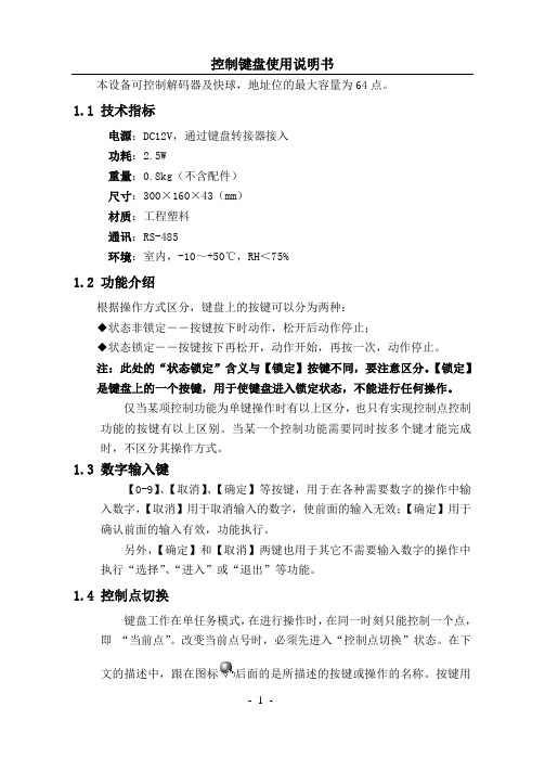
本设备可控制解码器及快球,地址位的最大容量为64点。
1.1 技术指标电源:DC12V,通过键盘转接器接入功耗:2.5W重量:0.8kg(不含配件)尺寸:300×160×43(mm)材质:工程塑料通讯:RS-485环境:室内,-10~+50℃,RH<75%1.2 功能介绍根据操作方式区分,键盘上的按键可以分为两种:◆状态非锁定――按键按下时动作,松开后动作停止;◆状态锁定――按键按下再松开,动作开始,再按一次,动作停止。
注:此处的“状态锁定”含义与【锁定】按键不同,要注意区分。
【锁定】是键盘上的一个按键,用于使键盘进入锁定状态,不能进行任何操作。
仅当某项控制功能为单键操作时有以上区分,也只有实现控制点控制功能的按键有以上区别。
当某一个控制功能需要同时按多个键才能完成时,不区分其操作方式。
1.3 数字输入键【0-9】、【取消】、【确定】等按键,用于在各种需要数字的操作中输入数字,【取消】用于取消输入的数字,使前面的输入无效;【确定】用于确认前面的输入有效,功能执行。
另外,【确定】和【取消】两键也用于其它不需要输入数字的操作中执行“选择”、“进入”或“退出”等功能。
1.4 控制点切换键盘工作在单任务模式,在进行操作时,在同一时刻只能控制一个点,即“当前点”。
改变当前点号时,必须先进入“控制点切换”状态。
在下文的描述中,跟在图标后面的是所描述的按键或操作的名称。
按键用“【”和“】”符号标识。
直接切换控制点在正常工作状态,按数字键后再按【确定】键,则直接切换到指定的点。
如果输入数字无效(超出系统的最大地址,对于本系统来说,应该在1-64之间),则输入后无效。
在输入数字过程中可用【取消】键退出输入数字状态。
输入数字时,所输入的数字会实时反色字体显示。
顺序切换控制点在正常工作状态下,按【向后】键,则切换到下一个控制点,如果点号已到最大地址,则返回最小地址。
按【向前】键则切换到上一点。
1.5 摄像机控制键位于键盘右侧,可以控制镜头的变倍、聚焦、光圈等动作。