ICEM_CFD_网格划分入门
ICEM网格划分原理
ICEM网格划分原理ICEM(Icem CFD)是一种用于流体力学计算的网格生成软件,广泛应用于航空航天、汽车、能源、船舶等领域。
ICEM网格划分原理主要包括松劲网格划分、结构化网格划分和非结构化网格划分三个部分。
下面将详细介绍这些原理。
1.松劲网格划分:松劲网格划分顾名思义是指网格的单元格可以灵活地重新排列和处理。
通常用于处理比较复杂的几何形状。
计算机先将几何形状映射到一个参数空间中,然后网格划分软件根据给定的规则生成初始网格。
网格可以通过细化和简化单元格来调整,以适应不同的模拟需求。
优点是可以对复杂几何形状进行灵活处理,但由于网格的复杂性,计算效率较低。
2.结构化网格划分:结构化网格划分是指网格按照一定的规律排列,形成规则的矩形或立方体结构。
这种网格划分方法适用于较简单的几何形状,如长方体或柱体。
结构化网格划分的原理是先将几何形状划分为一定数量的网格单元,然后再根据需求进行细分或剖分,以满足数值计算的精度要求。
结构化网格划分的优点是计算效率高,但对于复杂几何形状的处理能力有限。
3.非结构化网格划分:非结构化网格划分是指网格以不规则的三角形、四面体或多边形等形式排列,适用于包含复杂流动特性的几何形状。
非结构化网格划分的原理是先根据几何形状创建一个初始网格,然后利用边界层法、代数生成法、移动网格法等技术对网格单元进行优化和调整,以满足数值计算的要求。
非结构化网格划分的优点是适用范围广,可以处理复杂的几何形状和边界条件,但计算效率相对较低。
除了以上三种基本的网格划分方法,ICEM还提供了一系列的划分技术和工具,如自适应网格划分、边界层自动生成、网格加密等。
自适应网格划分是指在计算过程中根据流动场的变化,动态地调整网格分辨率和密度,以获得更准确的计算结果。
边界层自动生成是指根据流动特性和模拟条件自动生成边界层,以精确模拟边界层流动。
网格加密则是通过增加网格单元数量来提高计算精度,适用于需要高精度模拟的流动问题。
ICEM_CFD混合网格
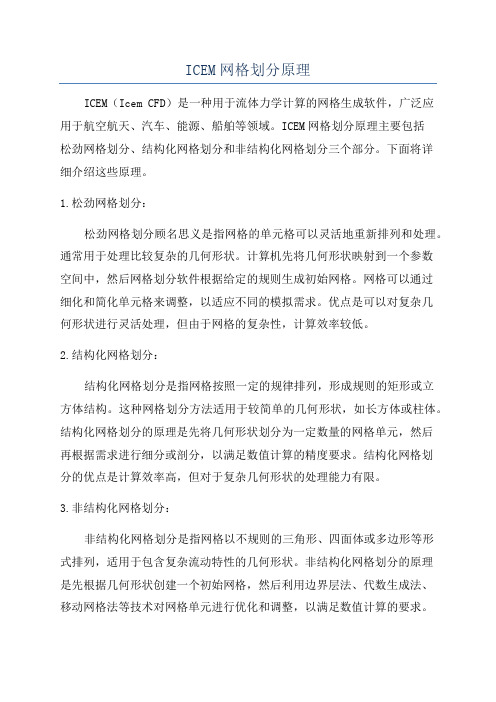
ICEM CFD中合并多个网格对于结构十分复杂的几何模型,若能够将几何体分割成多个部分由多人分别进行网格划分,生成网格后能够对网格进行组装,这恐怕是很多人梦寐以求的功能了。
其实很多前处理软件都具有此功能。
今天要说的是如何在ICEM CFD中实现此功能。
为了简单起见,这里用一个非常简单的模型进行演示。
当然复杂的模型的处理方式也是相同的。
我们要处理的几何模型如图1所示。
一个L型整体块被切割成3份。
分别导出为3个不同的几何文件。
按图中标示的顺序分别导出为1.x_t,2.x_t,3.x_t,当然其他的格式也无妨。
但是最好是在同一个体上进行切割,否则网格组装的过程中会存在定位的问题。
同一个体上切割的几何则不会存在几何坐标定位的问题。
图1 原始几何图2 几何1生成的网格图3 保存网格1、将几何1.x_t导入到ICEM CFD中进行网格划分。
注意千万保证单位的一致,切记。
这里是一个长方体,网格划分方法就不多说了。
预览网格如图2所示。
选择菜单File > Mesh > Load From Blocking生成网格。
2、保存网格。
选择File > Mesh >Save Mesh As…,我们这里保存已生成的网格为1.uns,后面组装的时候要用到此文件。
3、按照相同的步骤对模型2与模型3进行网格文件,同时保存网格文件为2.uns与3.uns。
图4 模型2的网格图5 模型3的网格4、网格组装先导入1.uns,点击菜单File > Mesh >Open Mesh…,选择第2步保存的网格文件1.uns,导入模型1的网格。
以同样的菜单,选择2.uns,会弹出对话框如图6所示。
注意此时选择Merge,否则如果选择Replace的话,则只会导入模型2的网格,将模型1的网格替换掉,这不是我们想要的。
接下来我们以相同的步骤导入3.uns,同样选择Merge。
导入后网格如图7所示。
图6 对话框图7 全部倒入后的模型5、导出网格以常规方式导出网格。
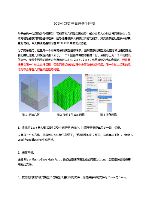
ANSYS ICEM CFD从入门到精通三维模型结构网格划分管内叶片模型详解
ANSYS v11.0
面网格尺寸
#1
#2
• Mesh > Set Meshing Params by Parts
• 按照提示设置大小
• Apply 并且 Dismiss
• Blocking > Pre-Mesh Params
• 接受默认值 Update Sizes 并且单击 Apply
• 在模型树中使 Pre-Mesh 可见,当提示重新计算是 单击Yes
– 键入‘a’ 选则全部物体或是
#3
在Select geometry 栏中单击
‘all entities’
9/9/05
ANSYS ICEMCFD V10
Workshop
Inventory #002277
D5-5
ANSYS v11.0
对顶点建立关联
#1
#2
Workshop
• 把一个顶点和一个几何点建立关联后, 块的顶点就会移动到那个点上
+Y
• 选择 Split Block > Split Block
• Split Method 是 Screen Select
• 单击左键并且拖住其中的一条边如图所示– 它变成红色的高 亮线
– 移动鼠标直到新的分割线的位置大体上在叶片的一端时 放开鼠标
– 中键确认分割位置
• 重复操作在中心和另一端进行分割
ANSYS ICEMCFD V10
Inventory #002277
D5-6
ANSYS v11.0
对边进行关联
#1
#2
Workshop
• 选择 Associate > Associate Edge to Curve – 在管的一侧选择4条边 – 在同一侧选择4条曲线
ANSYS ICEM CFD 网格划分教程2
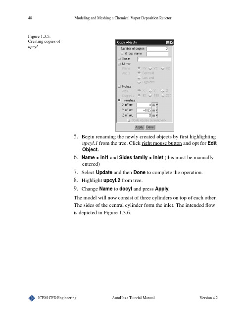
48Modeling and Meshing a Chemical Vapor Deposition ReactorFigure 1.3.5:Creating copies ofupcyl5.Begin renaming the newly created objects by first highlightingupcyl.1 from the tree. Click right mouse button and opt for EditObject. > inl1 and Sides family > inlet (this must be manuallyentered)7.Select Update and then Done to complete the operation.8.Highlight upcyl.2from tree.9.Change Name to docyl and press Apply.The model will now consist of three cylinders on top of each other.The sides of the central cylinder form the inlet. The intended flowis depicted in Figure 1.3.6.Modeling and Meshing a Chemical Vapor Deposition Reactor 49Figure 1.3.6:The intended flow forthe CVD reactor1.3.4: Creating ObjectsCreating CylindersCreate additional Cylinders by choosing Create cylinders iconfrom the top menu bar from each of following.Outduct1.Name > outduct 2.Plane > xz 3.C enter coordinates: (0.5, 0, 0.5)4.Height: 0.355.Radius: 0.156.Type > fluidNote: The changes are automatically implemented once the objectType is selected.Susceptor > susceptor2.Plane > xz3.C enter coordinates:(0.5, 0, 0.5)50Modeling and Meshing a Chemical Vapor Deposition Reactor4.Height: 0.375.Radius: 0.036.Type > hollowSusceptor Top > susc-top2.Plane > xz3.C enter coordinates: (0.5, 0.37, 0.5)4.Height: 0.035.Radius: 0.26.Type > hollowThe Cylinders created so far are shown in Figure 1.3.7.Figure 1.3.7:View of theCylinders created sofarCreating CirclesInlet1.Select Create circles icon from the top menu bar to create acircle. Select it from the tree and choose for Edit object uponclicking right mouse button. Together you get screen as shownin Figure 1.3.8.Modeling and Meshing a Chemical Vapor Deposition Reactor512.Change the Name to top-inl, signifying that this object will bethe top inlet to the reactor.3.Plane > X-Z4.C enter coordinates: (0.5, 0.5, 0.5)5.Radius: 0.036.Face family > inlet7.Press Update to complete the modifications.Figure 1.3.8:Circles edit windowwith specificationsfor top-inlNow create the remaining Circles using Create circles icon fromthe top menu barSubstrate > substrate2.Plane > X-Z3.C enter coordinates: (0.5, 0, 0.5)4.Radius: 0.25.Select Update and Done to complete the operation.Outlet > outlet52Modeling and Meshing a Chemical Vapor Deposition Reactor2.Plane > X-Z3.C enter coordinates: (0.5, 0, 0.5)4.Radius: 0.155.Face family > outlet (The user should enter this manually).6.Press Update and Done.The geometry for the CVD Reactor is now complete (Figure 1.3.9). Figure 1.3.9:Complete CVDreactor, with thecreated Circlesactivated1.3.5: Mesh GenerationCreating Cartesian Mesh1.From the AutoHexa viewing window, select Model > Gener-ate mesh to open the Mesh control window shown in Figure1.3.10. This is where all the mesh utilities are accessible.2.Select Mesh type > Cartesian to create a grid that is alignedwith the coordinate axes and quickly generated. Using thedefault parameters, select Generate mesh.Modeling and Meshing a Chemical Vapor Deposition Reactor53 Figure 1.3.10:Mesh controlwindow with thedefault parameters forthis tutorialCut planes1.Begin by Orienting the model to the Home position.2.Toggle on Mesh control > Display > Cut plane > Set position> Vertical - screen select.3.Click the left-mouse button in the center of the Domain in theAutoHexa viewing window.4.Orient > Orient positive X, and then select Mesh control >Display > Display mesh to obtain the diagram shown by Fig-ure 1.3.11.54Modeling and Meshing a Chemical Vapor Deposition ReactorFigure 1.3.11:Mesh cut plane asseen from thepositive X view usingdefault parametersLimiting Element Size1.The large element size may be controlled by adjusting the Uni-form spacing. Select Mesh control > Generate > Uniformspacing > (X count, Y count, Z count) > (50, 50, 50).2.Press Generate mesh to recalculate the mesh with the modi-fied counts. The new mesh should yield much finer mesh (i.e.50x50x50 nodes in a regular grid).3. Refer to Figure 1.3.12 to see the newly defined mesh cut plane. Figure 1.3.12:Diagram of the meshcut plane with newlyspecified X, Y, and Zcounts and higherelement count thanwhile using defaultparametersModeling and Meshing a Chemical Vapor Deposition Reactor55 Surface Elements1.To view the mesh on various parts of the reactor itself, first turnoff the Mesh control > Display > Cut plane utility for aclearer view.2.Select Display tab and turn on Surface and Current type. Thiscreates a mesh on the current object type that is selected fromthe Model menu. In this situation, the current object type isCircle. The mesh will appear as in Figure 1.3.13.Figure 1.3.13:Reactor with Surfaceelements meshdisplayed on currentobject type Circles.3.Select File > Save project from the AutoHexa viewing win-dow to save both the model and the mesh.56Modeling and Meshing a Chemical Vapor Deposition Reactor57Tutorial Example 1.4: Modeling and Meshing a LabOverview This tutorial, like the first tutorial, will focus on creating alaboratory for analyzation of the airflow through the room.Ventilation ducts on one side of the lab will supply air to the room,and a large fan on the other side of the lab will act as an outlet vent.The air will need to travel through the room, over and around thecreated obstructions, and depart through the exit vent. Thissimulation will illustrate the flow distribution inside of the room,allowing us to place the ventilation ducts at optimal locations thatare most beneficial to the occupant.Operations introduced in this example Starting a New Project•Initializing AutoHexa and beginning the projectCreating Objects•Developing the model, utilizing Domain, Hexas, Cylinders, Polygons, Circles andQuadsCopying Objects•Creating multiple entities by copy ing previously createdgeometryCreating Groups of Objects•Placing multiple objects into one Group, easing the copy ingprocessMoving Objects•Utilizing the Move function to translate geometrical entitiesinto new locationsMesh Generation•Generating Hexa mesh•Modifying the Per-object params•Generating Tetra meshConfiguration Options•Altering the Minimum object separation•Sorting the object edit lists, AlphabeticallyPrinting Screen•Doing Annotation, adding markers and getting a hardcopy ofthe modelSummary Creation•Accessing a summary of the specifications used in the cre-ation of the model1.4.1: Starting the Project1.Load ICEM CFD to open the main Mesh Editor viewingscreen, as well as the MED messages window and the Displaywindow. A File selection window should also appear, with theprompt to Select an ICEM CFD project to open,2.Type the new project name as tutorial-4 and pressAccept.3.Meshing > AutoHexa will initialize the AutoHexa modelingsystem.1.4.2: Creating ObjectsCreating the Domain1.Begin the creation of the territory of the laboratory by selectingModel > Domain from the tree.2.Resize the Domain with the following assignments: S tartpoints > (xS, yS, zS) -> (0, 0, 0) and E nd points > (xE, yE, zE)-> (10, 5, 6)3.Press Apply to activate the changes.4.Notice that the Domain is larger than the viewing window --select Orient > Isometric view to achieve a better view asshown in Figure 1.4.1.Figure 1.4.1:The modified domainCreating the HexasThe Divider1.To begin creation of the divider, select Create hexas icon fromthe top menu bar. > divider3.S tart points: (1, 0, 2.5) and E nd points: (6,4.5, 2.6)4.Select the object Type > hollow, since it is unnecessary to sim-ulate the heat transfer within the divider.Note: The changes are automatically activated when the objectType is assigned.5.Upon examination of the model, the user should notice that thedivider does not touch the wall on the low end of the X-axis.This entity may be moved by selecting Options > Interactiveediting from the tree. Toggle off Y and Z (Figure 1.4.2). Thisrestricts the motion of the divider to only along the X-axis. Figure 1.4.2:Restricting themotion of the divider6.Move the cursor to an edge of the divider. While holding theshift key down, press the middle mouse button, and drag thedivider towards the low end of the X axis, so that the divider isagainst the wall (Figure 1.4.3). The new S tart points are (0, 0,2.5), and the E nd points are (5, 4.5, 2.6).Figure 1.4.3:The new position ofthe dividerThe Worktable1.Click on Create hexas icon to create a new Hexa. > wktable3.S tart points: (6, 0, 3) and E nd points: (10, 1, 4)4.Type > solid5.Press ApplyThe Machine1. Click on Create hexas icon to create a new Hexa. > machine3.S tart points: (7, 1, 3.25) and E nd points: (10, 1.5, 3.75)4.Type > solid5.Press ApplyThe Person1.To begin creation of a person standing in front of the machine,click on Create hexas icon to create a new Hexa. > body3.S tart points: (6, 0,4.25) and E nd points: (7, 1.25, 4.5)4.Type > solid5.Press Apply6.To create the person’s head, click on Create hexas icon to cre-ate a new Hexa. > head8.S tart points: (6.25, 1.75, 4.25) and E nd points: (6.75, 2, 4.5)9.Type > solid10.Press Apply11.The person’s body and head is now complete. Refer to Figure1.4.4 to see the completed geometry created so far.Figure 1.4.4:The completegeometry created sofar1.4.3: Copying ObjectsThe Drawers1.The user will now add a file cabinet with three drawers to themodel. Click on Create hexas icon to create a new Hexa. > drawer13.S tart points: (0, 0, 0) and E nd points: (1, 0.5, 0.5)4.Type > solid5.The remaining drawers will have identical dimensions to thefirst drawer. To begin the Copy ing process, highlight drawer1from the Tree, click right mouse button on it and select Copyobject to obtain the Copy objects window, as shown in Figure1.4.5. Enter the following values.6.Number of copies > 27.Translate > Y offset > 0.5Figure 1.4.5:Copy panel8.Press Apply to create the remaining drawers. Proceed to pressDone.9.Highlight drawer1.1 from the tree and change its Name todrawer2. Select Apply when complete.10.Highlight drawer1.2 from the tree and change its Name todrawer3. Press Apply to update the change.Figure 1.4.6:The Hexas list can bemodifiedNote: Any of the three drawer s may be temporarily removed fromthe model in order to vary the conditions for the simulated flow.This is achieved by first selecting the desired object from the tree,pressing right button and then unselecting the Active option.Toggling on Active from the Inactive group from the tree, willreactivate the entity. To permanently remove an object from themodel, the user should first highlight the desired entity, and thenproceed to select Delete. This object then would show under Trashin the tree. The Undo option, however, can cancel the last action.1.4.4: Creating ObjectsCreating the PolygonThe Chair1.The user will now create a chair located next to the file cabinet.Click on Create polygons icon to create a new polygon.(Refer to Figure 1.4.7). > chair3.Plane > xy4. Height > 0.755.Highlight vert1 > (x1, y1, z1) -> (0, 1.25, 1)6.Highlight vert2 > (x2, y2, z2) -> (1.5, 0, ~)7.Highlight vert3 > (x3, y3, z3) -> (0, 0, ~)8.Type > solid9.Press Apply.Figure 1.4.7:Creation of chairusing polygons.10.Highlight vert1, as shown in Figure 1.4.711.Press Add once to create another vertex, vert2, and assign (x2,y2, z2) the values of (0.75, 0.5, ~).12.Press Add once again, creating vert3. (x3, y3, z3) > (1.5, 0.5, ~)13.To complete the chair and update the changes, select Apply.Refer to Figure 1.4.8 for the final shape of the chair.Figure 1.4.8:The final chairCreating the CylindersThe Table-legs1.Click on Create cylinders icon to create a new cylinder tobegin creation of the table-legs. > tleg13.Plane > xz4.C enter coordinates: (xC, yC, zC) > (2.25, 0, 0.5)5.Height: 0.756.Radius: 0.057.Type > solid8.To create tleg2, the user will copy tleg1. Highlight tleg1 fromthe tree,click right mouse button on it and select Copy object.This will open the Copy objects window.9.Number of copies > 110.Translate > X offset -> 1 > Y offset -> 0 > Z offset -> 011.Select Apply to create the copy, and then Done.12.Highlight tleg1.1 from the tree and change the Name to tleg2.13.Select Apply when complete with renaming the copied table-leg. Refer to Figure 1.4.9Figure 1.4.9:Geometry with Finaltable legs1.4.5: Creating Groups of Objects1.To place tleg1 and tleg2 into a group, access the tree. Clickright mouse button on Groups there and choose Create. > tlegs3.Select Orient > Orient negative Y. This will adjust the view,making tleg1 and tleg2 easily accessible.4.Right click on Groups > tlegs and choose Add > ScreenSelect.5.With the shift - left mouse button, select tleg1 and tleg2, turningthe entities red in color. Their names will appear under the treeas shown in Figure 1.4.10. Press shift - right mouse button toexit out of this selection mode.Figure 1.4.10:The tree6.To create the remaining table legs, the user should copy thenewly established group. In the tree, highlight tlegs underGroups, right click and then select Copy group. This willopen the Copy group tlegs window.7.Number of copies > 18.Translate > X offset -> 0 > Y offset -> 0 > Z offset -> 19.Press Apply to add the remaining table legs, and then Done.10.Highlight tleg1.1 from the tree, and change the Name to tleg3.Select Apply to activate the change.11.Highlight tleg2.1 from the tree, and change the Name to tleg4.Select Apply to activate the change.1.4.6: Creating ObjectsCreating the QuadsThe Table-top1.Click on Create quads icon to create a new quad. > ttop3.Plane > xz4.S tart points: (2, 0.75, 0.25) and E nd points: (3.5, ~, 1.75)5.Press Apply to complete the operationThe Inlet vents1.Click on Create quads icon to create a new quad > inl13.Plane > xy4.S tart points: (1, 0, 6) and E nd points: (4, 1, ~)5.Select this object from the tree, click right mouse button andchoose Edit object. Go to Properties and say Face family > inlet (The user will need to manually enter this assignment).6.Select Done to complete the first inlet.7.To create inl2, the user will need to copy inl1. Highlight inl1from the tree, click right mouse button and select Copy object to open the Copy objects window.8.Number of copies > 19.Translate > X offset -> 5 > Y offset -> 0 > Z offset -> 010.Select Apply > Done,11.Highlight inl1.1 and change the Name from inl1.1 to inl212.Select Apply to complete the operation. Refer to Figure 1.4.11for the completed quads.Figure 1.4.11:Geometry withcompleted quads1.4.7: Moving ObjectsThe air will enter the room via the inlet and exit via outlet fan thatwill be constructed during this section.Creating the CirclesThe Outlets1.Click on Create circles icon to create a new circle. > out13.Plane > xy4.C enter coordinates: (2.5, 2.5, 0)5.Radius: 0.756.Select this object from the tree, click right mouse button andchoose Edit object.Go to Properties and say Face family >outlet (The user will manually enter this assignment).7.Select Done to complete the outlet.8.Observing the configuration, the user should notice that out1 ispoorly situated behind the room divider. Alter its location byselecting Move object up on clicking right mouse button onout1 in the tree.9.Translate > X offset -> 5 > Y offset -> 0 > Z offset -> 010.Select Apply to move out1 to its new position, thus enabling itto remove hot air more efficiently.11.Select Done to complete the operation, and notice that the xCcenter coordinate in the Edit window has increased by 5 unitsto 7.5, as shown in Figure 1.4.12.Figure 1.4.12:New center positionof the circleThe Exhausting Create circles icon, the user will create an exhaust fan.Click on Create circles icon to create a new circle. > exhaust3.Plane > yz4.C enter coordinates: (10, 4, 3.5)5.Radius: 0.26.Select Apply to update the parameters.Creating the CylindersThe Tube1.The user will now create the tube needed to transport the hot airmoved by the exhaust fan, through the machine. Click on Cre-ate cylinders icon to create a new cylinder. > tube3.Plane > yz4.C enter coordinates: (7, 1.25, 3.5)5.Height: 1.256.Radius: 0.27.Type: fluid8.Select Apply to complete the task.Creating the CirclesThe Inlet Fan1.Click on Create circles icon to create a new circle. > inlfan3.Plane > yz4.C enter coordinates: (8.25, 1.25, 3.5)5.Radius: 0.26.Select this object from the tree, click right mouse button andchoose Edit object. Go to Properties and say Face family >source (The user will need to manually enter this assignment)7.Press Done to activate the modifications.When complete, the laboratory model should appear as in Figure1.4.13.Figure 1.4.13:Solid model of thelaboratory1.4.8: Mesh GenerationThe Hexa Mesh1.To begin mesh creation, select Model > Generate mesh. TheMesh control window depicted in Figure 1.4.14 will appear.2.Making sure that Mesh type > Hexa unstructured is selected,select Generate mesh, using the default parameters.Figure 1.4.14:Mesh ControlwindowNote: The mesh comes pretty decent in this geometry. Lessdistortion of the element quality means higher quality of mesh,providing the solver with an easier time with convergence. Checkthe AutoHexa messages window, and notice that there are nosignificantly distorted elements with a quality between 0 and0.25. There are a few between 0.25-0.5. To see where theseelements are located, go to Mesh control > Quality, replot thehistogram from 0.25 to 0.5 and then select the bars in the histogramto display the elements on the screen.1.4.9: The Tetra Meshing the same model, create a Tetra mesh by selecting Model> Generate mesh will open Mesh control window. From thiswindow select Generate > Mesh Type > Tetra. Unselect Maxtetra size, as well as Per-object params, as shown in Figure1.4.15.Figure 1.4.15:Tetra parameterwindow2.Continue by selecting Generate mesh. When complete, thenewly created tetra mesh should consist of approximately184000 elements and 42000 nodes.3.Select Display > Display mesh > Surface.4.Press Close to exit the Mesh control window.5.Select File > Save project to save the model and mesh.1.4.10: Configuration OptionsBefore a mesh is actually generated, AutoHexa will check themodel for gaps existing between objects that may interfere with thecreation of a uniform mesh.1.To modify the default Minimum object separation, selectOptions > Settings from the tree which will open the Config-uration options window seen in Figure 1.4.16.This feature is especially useful in cases where small gaps maypervade throughout the model, in which case AutoHexaautomatically closes any gaps that are larger than the specifiedMinimum object separation.Figure 1.4.16:ConfigurationOptions window2.The color of all the objects, text, and mesh lines are modifiableunder the Options > Graphical options.3.Since there were many Hexa objects created in this tutorial, itmay be beneficial to sort the object list alphabetically. From themain menu, select Tree > Sort > Alphabetical. Figure 1.4.17illustrates the difference between the two object lists.Figure 1.4.17:Left: before sorting,right: after sorting1.4.11: Hardcopy Creation1.At this point, it may be useful to print out a diagram of the finalmodel. Select File > Print screen to open the Print optionswindow shown in Figure 1.4.18Figure 1.4.18:Print options window2.The user may select Full screen or Mouse selection or Pixellocation.3.Select Color Mode > Color.4.Continuing on in the Print options window, select Print to getthe hardcopy.5.The user can change the Title of the project. In the tree go toProblem setup > Title/notes to get a window as shown in Fig-ure 1.4.19.Figure 1.4.19:Title/notes window6.The appearance of the printout may be further customized byaccessing the View > Add Marker from top menu bar. This willopen the Add Marker window shown in Figure 1.4.20. Thisallows the user to add text to the display at a specified location. Figure 1.4.20:Add marker window7.You can do the annotations on the screen by opting for Edit >Annotations from the top menu bar. This will open up a win-dow as shown in Figure 1.4.21.Figure 1.4.21:Annotations window1.4.12: Summary CreationAlong with a hardcopy of the model itself, a hardcopysummarizing the specifications you have used in its creation maybe useful. A printout of this information is accessible by selectingEdit > Summary from the top menu bar. This will open theParameter summary window as shown in Figure 1.4.22.78Modeling and Meshing a Lab Figure 1.4.22:Parameter summarywindow79Tutorial Example 1.5: Modeling and Meshing a WingOverview This tutorial will guide the user through creating a wing-shapedobject inside of a room in order to analyze the airflow over, under,and around the wing. On one side of the room, an inlet vent permitsair to flow into a duct that channels the airflow directly towards thewing. The airflow will pass by the wing and head directly towardthe outlet vent on the opposing room wall, passing over, under, andaround the wing during its travel.Operations introduced in this example Starting a New Project•Initializing AutoHexa and beginning the projectCreating Objects•Developing the model with the following geometrical entities: Domain, Ellipsoidal cylinders, Ellipsoids, Polygons andQuadsCopying Objects•Making modifications in the Copy window, copying the poly-gons80Modeling and Meshing a WingMesh Generation•Creating Tetra meshCreating a Cut Plane•Utilizing Cut plane techniques to obtain a clearer view of thetetra mesh around the wing1.5.1: Starting the Project1.Load ICEM CFD to open the main Mesh Editor viewingscreen, as well as the MED messages window and the Displaywindow. A File selection window should also appear, with theprompt to Select an ICEM CFD project to open.2.Type the new project name as tutorial-5 and pressAccept.3.Meshing > AutoHexa will initialize the AutoHexa modelingsystem.1.5.2: Creating ObjectsCreating the Domain1.Begin the creation of room by selecting Model > Domain fromthe tree.2.Resize the Domain with the following assignments: S tartpoints > (xS, yS, zS) -> (0, 0, 0) and E nd points > (xE, yE, zE)-> (100, 50, 40)3.Press Apply to activate the changes.4.Notice that the Domain is larger than the viewing window --select Orient > Isometric view to achieve a better view, asshown in Figure 1.5.1.Modeling and Meshing a Wing81 Figure 1.5.1:The Isometric viewof the modifiedDomainCreating the Ellipsoidal CylindersUtilizing an ellipsoidal cylinder will allow the user to create themain wing shape. Ellipsoidal cylinders are specified by twoellipses that are the ends of the object. Each end has a C entercoordinate (C1 on one end, and C2on the other), and twocorresponding radius vectors (vec1 and vec2 -- both assignedvalues at the Top and the Bottom of the wing.) If needed, theOnline Reference Manual provides a more detailed description ofthe ellipsoidal cylinder objects.1.From the AutoHexa top menu bar, select Create e. cylindersicon. Then proceed to select oval.1 from the right side tree,press right mouse button and choose option Edit object asshown in Figure 1.5.2.82Modeling and Meshing a WingFigure 1.5.2:E. cylinders editwindow with thespecified parameters2.Change the Name from oval.1 to wing13.Enter the bottom center (Bot cent) X, Y and Z coordinates as(48, 25, 0)4.Enter the top center (Top cent) X, Y and Z coordinates as (50,25, 18.25).5.(Bot vec1 x, Bot vec2 x, Top vec1 x, Top vec2 x) > (0, 4, 0, 2)6.(Bot vec1 y, Bot vec2 y, Top vec1 y, Top vec2 y) > (1, 0, 0.25,0)7.(Bot vec1 z, Bot vec2 z, Top vec1 z, Top vec2 z) > (0, 0, 0, 0)8.Family Type > Hollow from Properties9.Sides family > wing (manually typed)10.Select Update and Done to activate the changes as shown inFigure 1.5.3Modeling and Meshing a Wing83 Figure 1.5.3:wing1 with thelabeled top andbottom vectorsCreating the EllipsoidTo create the rounded tip of the wing, the user will implement anellipsoid object. An ellipsoid is a 3-dimensional ellipse where allthree axes are aligned to the coordinate axes. Like Hexa objects,Ellipsoids are specified by a bounding box. The Online ReferenceManual provides more information on ellipsoids.1.From the top menu bar, select Create ellipsoids icon. > wing-tip3.S tart points: (48, 24.75, 18) and E nd points: (52, 25.25, 18.5)4.Press Apply to confirm the changes.5.For a clearer view of the newly created Ellipsoid object, deacti-vate the wing by clicking right mouse button on wing1 fromthe tree and de-selecting Active. This temporarily removeswing1 from the display.6.Zoom in on the Ellipsoid object that is visible on the screenwith the right-mouse button.7.In the tree highlight wing-tip to apply more changes.8.Once in the Ellipsoid frame (Figure 1.5.4), unselect Corners >xyz, Xyz, xYz, XYz. Only half of the Ellipsoid is necessary torepresent the wing-tip.9.Type > hollow84Modeling and Meshing a WingFigure 1.5.4:Ellipsoids object editwindow with thespecifications10.Set the Outside family to wing from the edit window. Get thatwindow by clicking right mouse button on wing-tip in the treeand opting for Edit object.11.Press Update to activate the modifications, and then Done toclose the edit window. This should yield the model displayed inFigure 1.5.5.Figure 1.5.5:Close-up view of thewing-tip after settingthe parameters.12.Reactivate wing1 by toggling on Activate from Inactive groupfrom the tree to achieve Figure 1.5.6.。
ICEM_CFD_关于六面体网格的划分
面的块的定选 ”过穿“ dirg-O –
面加添中程过dirg-O建创在
面加添 – sdirG-O 建创
52
0.5 tnemnorivnE*IA/DFCMECI
8-3-2102
dirg-L 是 向方个一另在 dirg-C是上向方 个一在 来起看
块分划形 角三对来用以可 sdirg-O一之分四
)dirg-L( dirg -O 一之分四
寸尺格网体面六义定速 快寸尺格网线曲和面曲置设过通 – 寸尺格网置设
寸尺格网置设 – 程过块分
31
0.5 tnemnorivnE*IA/DFCMECI 离距元单格网大最上egde– ecapS xaM 离距的点格网个两前侧2 edis – 2 gnicapS 率比长生的心中向2 edis从– 2 oitaR
块择选dirg-O 为
dirG-O 省缺 – sdirG-O建创
42
0.5 tnemnorivnE*IA/DFCMECI
8-3-2102
面这过穿 dirg-O
体何几杂复 –
面平称对 –
端末道管 – 子例用使
)dirg-C( dirg-O 半 面个这过穿 dirg-O
面加添”分部坦平“在 ,下况情般一 –
格 网-O 体 绕
32
0.5 tnemnorivnE*IA/DFCMECI
8-3-2102 xetrev 或 ,egde ,ecaf绕环skcolb 择选
点顶和边部内有所有含块部内 :意注
D3 ni skcolb 7
D2 ni skcolb 5
择选�点角对�dohtem renroc 2 ,�点绕环�xetrev dnuora ,�边绕环�egde dnuora ,�面绕环�ecaf dnuora ,trap ,�部全�lla ,�视可�elbisiv过通以可 –
icem_cfd网格设置参数[指南]
![icem_cfd网格设置参数[指南]](https://img.taocdn.com/s3/m/16b51312e97101f69e3143323968011ca200f757.png)
一般来说,线和边单位参数设置,Height、Height Ratio和层数是常用的3个参数。
如果只设置了层数而没有设置高度和高度比的话,高度会视同等于最大单元尺寸,高度比视同为1.(1)Maximum size最大单元尺寸,真实值是该值与总体单元缩放因子的乘积。
如果采用Curvature/Proximity Based Refinement or Maximum Deviation也可以突破这个限制(2)Height指定垂直表面或者曲线的第一层单元的高度,对于体单元,这个参数能够影响六面体和菱柱的初始网格高度。
对于Patch Dependent面网格,使用于曲线时,这个值能够影响沿着曲线的四边形网格的初始高度。
例如,可以用于指定沿着螺栓孔一周的四面形网格的初始高度。
(3)Height Ratio从面第一层单元开始的扩大率,这个值乘以前一层网格的高度来决定下一层网格高度。
默认值为1.5,可以从1.0~3调整。
如果值小于1.0,将会取其倒数,如果值大于3,将会忽略该设置直接采用默认值。
当用于曲线时,能影响Patch Dependent meshing,当定义了初始高度和层数后,它决定了下一层四面体单元的生长率。
当采用Adapt Mesh Interior设置后,它会影响从曲线尺寸到面尺寸过渡的快慢。
(4)Num Layers从面或者曲线开始增长的层数(5)Tetra width创建指定数目的三角形层,这些层单元尺寸由最大尺寸指定。
(6)Tetra size ratio控制三角形单元的生长率,用于三角形网格。
(7)Min size limit限定最小单元尺寸。
这个参数只用于Curvature/Proximity Based Refinement选项。
(8)Max Deviation一种基于从三角形或者四边形面单元中心和实际几何形状的差别来再次细分的方法。
如果距离大于该值,单元会自动分裂,新的节点将会投影到几何体上。
ICEM_CFD_关于-网格编辑方法
– 对于突出物, Split Spanning Edges 保证体积 内部的节点
2020/5/25
ICEMCFD/AI*Environment 5.0
19
网格修复
2020/5/25
Move Nodes: 移动节点 热键: m
– 选择节点并移动鼠标
• 映射到指定的位置的节点无法移动
ICEMCFD/AI*Environment 5.0
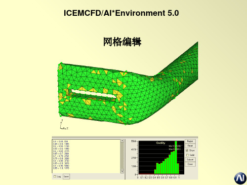
网格编辑
网格编辑
• 强大易于使用的网格编辑工具
– 操控网格 – 检查网格 – 改进网格质量
• 拥有自动和手动工具 • 编辑导入或创建的网格
2020/5/25
ICEMCFD/AI*Environment 5.0
2
2020/5/25
检查网格
热键: Ctrl-d
?angle网格?aspectratio纵横比?skew歪斜?surfacedeviation曲面偏差?distortion扭曲?maxwarp最大歪曲?minedge最小边icemcfdaienvironment502012389控制质量直方图?在直方图左击选择相应直方条变成粉红色如果show被选中这些单元在显示窗口高亮显示??如果solid被选中这些单元显示为实体轮廓即使有其它单元以框架形式显示?可以选中多个直方条高亮显示一定质量范围的网格单元icemcfdaienvironment5020123810控制质量直方图?y轴拥有很大的刻度范围因为对其小的柱状体感兴趣使用replot按钮重新设置直方图的范围
• 映射到曲线/曲面的节点只能在曲线/曲面上移动
• 内部的体积点可以在屏幕确定的平面上移动
– Move nodes Type-move multiple 类型
ICEM-CFD基础教程入门

• 对不完整的几何体有容错能力
2023/10/21
ICEMCFD/AI*Environment 5.0
9
特性: 六面体网格划分
• 强大的六面体网格生成能力 • 自顶向下或自底向上分块方法 • 复杂模型网格的快速生成 • 快速重复操作
– 弹性分块适合相似几何模型 – 对几何尺寸改变后的几何模型自动重划分网格
22
模型树
• 设定窗口显示的图形 • 包含5个主要项目; Geometry几何, Mesh网格,
Properties属性, Parts部分 and Subsets子集 • 单击模型树分枝上的眼镜图标控制可见与否
– 红 X 图标表示 这一分枝(包含所有子分枝) 不显示
– 整个眼镜图标表示这一分枝下所有可显示项均可见
率
• Tri (STL-like):
– 生成三角面面网格 – 没有内部点
2023/10/21
ICEMCFD/AI*Environment 5.0
11
特性: 混合网格
• 棱柱层
– 在四面体网格中提高边界层计算结果
• 六面体和四面体区域交界处采用棱锥体 网格
2023/10/21
ICEMCFD/AI*Environment 5.0
21
视图操作
1 使用键盘: H – 主视图
Shift X - +X视图 Shift Y - +Y视图
Shift Z - +Z视图
2 单击视图中坐标图标
3 View > View Control
例如: 单击 Y 轴 使Y 轴 垂直屏幕
保存视图
2023/10/21
ICEMCFD/AI*EnvironmenEMCFD/AI*Environment 5.0
- 1、下载文档前请自行甄别文档内容的完整性,平台不提供额外的编辑、内容补充、找答案等附加服务。
- 2、"仅部分预览"的文档,不可在线预览部分如存在完整性等问题,可反馈申请退款(可完整预览的文档不适用该条件!)。
- 3、如文档侵犯您的权益,请联系客服反馈,我们会尽快为您处理(人工客服工作时间:9:00-18:30)。
WorkBench ICEM CFD 网格划分入门111AnsysWB里集成了一个非常重要的工具:ICEM CFD。
它是一个建模、划分网格的集成工具,功能非常强大。
我也只是蜻蜓点水的用了几次,感觉确实非常棒,以前遇到复杂的模型,用过几个划分网格的工具。
但这是我觉得最方便和最具效率的。
网格划分很大程度上影响着后续的仿真分析——相信各位都有所体会。
而ICEM CFD特别长于划分六面体网格,相信无论是结构或流体(当然铁别是流体),都会得益于它的威力。
ICEM CFD建模的能力不敢恭维,但划分网格确实有其独到之处。
教程开始前,作一个简单的原理介绍,方面没有使用过ICEM CFD的朋友理解主要的任务:111如下图:1:白色的物体是我们需要划分网格的,但是它非常不规则。
2:这时候你一定想:怎么这个不规则呢,要是它是一个方方正正的形状多好(例如红色的那个形状)01111于是有了这样一种思想:1:对于异型,我们用一种规则形状去描述它。
2:或者说:如果目标形状非常复杂,我们就用很多规则的,简单的形状单元合成在一起,去描述它。
之后,将网格划分的设置,做到规则形状上。
最后,这些规则,通过最初的“描述”关系,自动的“映射”到原先的复杂形状上——问题就得到了解决!!!ICEM CFD正是使用了这种思想。
如下是一个三通管,在ProE里做得02在ProE里面直接启动WB进入WB后,选择如下图:03111如下:1:代表工作空间里的实体2:代表某实体的子实体,可以控制它们的开关状态3:控制显示的地方04下面需要创建一个Body实体这个实体代表了真实的物体。
这个真实的物体的外形由我们导入的外形来定义。
——我们导入的外形并不是真实的实体。
这个概念要清楚。
但是今后基本上不会对这个真实的实体作什么操作。
这种处理方式主要是为工作空间有多个物体的时候准备的。
051:点击“创建Body”2、3:点选这两个点4:于是创建出一个叫“Body”的实体操作中,左键选择,中键确认,右键完成并退出——类似的操作方法很多地方用到,要多练习,今后就不特别说明了06下面需要创建我们最需要的东西:那个“规则的形状”ICEM CFD里,这个实体叫 Block可以如下方式创建之:07注意到我们现在多了一个黑框,怎么样,够规则吧?呵呵,开个玩笑。
还必须对这个黑框进行必要的“裁剪”之后才能用来“描述”我们的目标实体0809修剪Block实体的第一步是一个益智的工作:我们不妨简单绘制一下策略:因为我们的实际物体像一个变形的“T”形,因此,不妨就用“T”来变形。
最后要保留的部分用圆圈表示,不要得部分用“X”。
如下图:10如图:1:选择“Split”工具2:使用默认的第一个方法3:选择“选线”按钮4:在Block的黑线上选择,并“切”出一条黑线。
5、6、7、8、9:以此类推。
11最后的结果应该类似下图121:选择“Delete Block”2:选择“选择Block”按钮3:删除不需要的部分。
13得到类似的图形:14开始调节点的位置:1:选择“Move 顶点”2:选择默认方法3:选择“多选”——补充一个,我们一直使用Y向视图!5:将Y固定掉4:选择“选择点工具”6:之后调节Block的顶点,到类似下图的位置15注意到在每个Pip的弯处,Block与Pip不能很好的贴合,这是因为我们的Block还是粗糙。
因此,需要继续“Split”现有的Block,并继续调节Block的顶点。
方法就是重复上面的步骤,这里就不罗嗦了。
细分和调节后的图形类似下图,当然追求完美的朋友还可以继续细分——不过需要把握一个度的问题,因为细分得太多,也就失去“用简单描述复杂”这个出发点了。
16下面要做的是从Block到Pip的“对应关系指定”工作。
——尽管现有已经有了描述Pip的Block,但一些细节的地方,需要手工指定它们的对应关系,在复杂模型中尤为如此。
因为尽管软件有很大程度的智能,但它毕竟无法完全的自动的分析出我们需要的对应关系来。
关于指定“对应关系”的练习,最好请朋友们按照ICEM CFD 自带的教程来做几次。
特别是调节Block 的顶点技巧,和今后流体计算的网格质量有很大关系,不熟悉的朋友需要补补课了。
如下图:我们需要将Block上的这四个边同Pip三通处的连接部分“绑定”在一起。
相当于告诉软件:“今后这四条边就代表了这两条圆弧哦!”17方法如下:1:选择“Associate”2:选择“Edge to Curve”——Edge是Block上的,Curve是Pip上的3:选择Edges——注意这时必须要多选。
4:再选择“Curve”——这时候也要多选5:中键确认后,注意到已经制定了对应关系的边变成绿色。
18下一步就可以使用自动指定的功能了:1:选择“Associate”2:选择自动捕捉3:确定4:注意到现在Block已经“完美”的包裹住Pip 19另外,要将三个管口的Block的Edge和Pip的Curve“指定”对应关系,方法就和上面指定连接处的时候一样。
请大家自行操作了。
20之后,就可以设定Mesh的参数了。
1:打开实体参数设定窗口2:MaxSize设置为5——方向对了以后今后可以调节到更小。
3:HeightRetio设置为0.64:确认21激活刚才的设置,为Pre-Mesh做准备1:选择“Pre-Mesh 参数”2:默认更新所有设置3:确认22预览Mesh:1:设置为实体状态2:显示设置的推荐选项,朋友们可以自行调节3:结果应该和右图类似23关心一下Mesh质量:1:打开Mesh质量检查2:选择“Angle”——有很多种评价网格质量的方法,我比较喜欢这个3:右键点选不理想的部分4:选择“Show”5:这些单元格是目前的设置情况下,不太理想的地方24有很多种方法改善单元格的质量比如我在Bolock上,相应的地方添加了一条线,调节的位置后,从新使用一次“自动包裹”——方法同前面的讲述再次更新Pre-Mesh参数后,检察质量,刚才的不良已经消除。
25重要提示:1:在制作Block的时候,Block顶点的位置,Bolock细分的效果,都可以在这样的循环操作中得到直观的结果。
2:划分网格,我个人觉得无外乎两步:一个清晰的思路,和不断的优化。
前者需要见多识广,后者需要耐心仔细。
如果是做结构分析,在这一步可以打住了,直接生成最终的单元格文件即可;但做流体的朋友还需要继续:做流体的边界层。
1:创见O型格也是一种Split2:选择创建O型格3:选择所有的格体4:选择出、入口(不需要O型结构的面)26观察其中一个口:1:绿色的线是原先Block的Edge(因为我们原先制定了它和Pip上物理开口的对应关系所以变成了绿色) 2:小一点的黑色线,代表了今后的O型格体!!!——ICEM CFD创建O型格的工作仍是在Block上开展的。
27在O型格上设置边界层的参数1:打开参数设置2:设置“线参数”3:选择一条连接O型和边缘的联线4:今后边界层为六层,因此格点为75:靠近外缘的厚度暂定为0.2——今后可以调整6:选择“复制参数”的功能7:将这个设置复制到所有类似的线上其中MeshLaw设置很有意思,同今后的求解器,液体属性等均有关系。
有兴趣的朋友自己去研究了。
我选择的是“Exponential1”28注意到此时O型到边缘的距离,就是我们刚刚设置了曾数等信息的那条黑线,还比较长因此,做如下修改:1:选择修改Block1.5:选择修改边长2:选择需要修改的边3:输入距离(注意“绝对距离”和“相对距离”的差别)29可以从新勾选“Pre-Mesh”注意到现在已经有O型结构了。
30后续的工作中:1:可以在“Pre-Mesh”上右键,选择“转换为非结构化网格”2:可以使用菜单项,输入需要后续分析的软件的对应格式。
3132结论:1:Ansys 的WB,对ICEM CFD的集成目前(至少我使用的版本),并不完美。
譬如ZCCBEST朋友提出的如何保持参数化的问题,我也不知道是否能实现。
但我想第一,ICEM CFD是非常棒的Mesh工具,主要还是用在复杂模型的Mesh上,并且侧重于Mesh 本身。
举例说,我用Maya制作的复杂模型,也可以在ICEM CFD中进行网格划分,并且生成的BLOCK文件可以被单独的保存下来,今后如果修改不大,则直接调用BLOCK文件,重复利用之即可(当然一般要做一些小的修改)。
第二:今天或许不能实现某些我们希望的功能,并非明天不行。
我想来论坛的朋友更多的是抱着学习的目的,所以请暂时把软件的瑕疵放一放,而不断地,毫无偏见地去提高自己第三:从Ansys近两年的发展看,我相信我们期望的那些宜用功能,肯定会被完善。
比如就我知道的:Ansys正在考虑将Ansoft,Fluent等才收购的重量级软件也集成到WB中来。
因此,我倡议大家,在“理想状态”到来前,不断地学习学习再学习,从而争取领先一步,步步领先!2:回顾我所发的几个教程,其实很大程度上是想为朋友们抛砖引玉,引导不熟悉仿真软件的朋友了解这个领域——毕竟我们在这方面也太落后了,很多行业根本没有这种意思。
朋友们或许为不同的公司打工,但今后的生产,何尝不都是用的我们中国人的资源。
能节约点是一点,于公于私都不无大利——至少我们要知道可以怎么样将这些东西用于我们的设计吧。
因此我真心的倡议大家共同建设这个板块,无私的交流日常的心得,真正达到共同提高的目的。
唉,不小心写多了。
忘记了“少说多做”的原则,但想到确实是发自肺腑的文字,不忍删除,就以之与朋友们共勉吧!!!——好累,抽根烟先!。