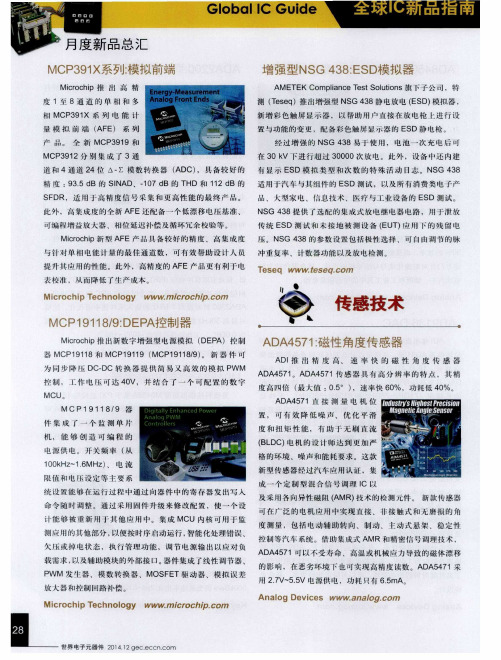
Teseq推出增强型NSG 438 静电放电(ESD)模拟器
esd实验分类
esd实验分类ESD(Electrostatic Discharge)实验是一类用于研究静电放电现象的实验。
静电放电是指在两个带电体之间突然放电的现象,常见于日常生活中,比如我们碰到金属物体时感到的一阵电流感。
ESD 实验可以帮助我们了解静电放电的原理、特性以及如何防止静电对电子设备的损害。
本文将从ESD实验的分类、实验原理以及实验过程等方面进行介绍。
一、ESD实验的分类根据实验目的和研究对象的不同,ESD实验可以分为以下几类:1. 静电放电特性实验:通过测量不同条件下的静电放电电流、电压和时间等参数,研究静电放电现象的特性和规律。
这类实验可以帮助我们了解静电放电的强度、持续时间以及放电过程中的能量转换等重要信息。
2. 静电防护实验:通过模拟真实的工作环境,测试和评估不同防护措施对静电放电的影响。
常见的防护措施包括接地、静电消除器、静电屏蔽等。
这类实验可以帮助我们选择合适的防护措施,减少静电放电对设备和人体的影响。
3. 静电放电故障实验:通过模拟静电放电引起的故障现象,研究静电放电对电子设备的损害程度和机理。
这类实验可以帮助我们预测和避免静电放电引起的故障,提高设备的可靠性和稳定性。
二、ESD实验的原理ESD实验的原理基于静电放电的物理过程。
当两个带电体之间的电势差达到一定程度时,电荷会通过空气或其他介质以电流的形式突然放电。
静电放电过程涉及电荷的积累、空气离子化、电流的流动等多个环节。
ESD实验的目的就是通过模拟和观察这些环节,揭示静电放电的机理和特性。
三、ESD实验的过程进行ESD实验需要一系列的实验步骤和实验装置。
下面是一般的ESD实验过程:1. 准备实验装置:根据实验的要求,准备相应的实验装置,包括静电放电发生器、测量仪器、试样等。
确保实验装置的可靠性和安全性。
2. 设计实验方案:根据实验的目的和要求,设计合适的实验方案,包括实验参数的选择、实验条件的确定等。
确保实验方案的科学性和可操作性。
增强型NSG438:ESD模拟器
及 采 用 各 向异 性 磁 阻 ( A MR ) 技 术 的 检 测 元 件 。 新 款 传 感 器
可 在厂 ‘ 泛 的 电 机 应 用 中 实 现 直 接 、 非 接 触 式 和 无 磨 损 的 角
新 增 彩 色 触 屏 显 示器 , 以 帮 助 用 户 直 接 在 放 电 枪 t进 行 设
置 与功 能 的 变 更 ,配 备 彩 色触 屏显 示器 的 E S D静 电 枪 。 经 过增 强的 N S G 4 3 8易 于 使 用 , 电 池 一 次 充 电 后 可
在 3 0 k V下进行超过 3 0 0 0 0次 放 电 。 此 外 ,设 备 中 还 内建
控制 , I 作 电 压可 达 4 0 V 并结 合 _ 『 ・ 个 可 配 置 的 数 字
MCU。
度高四倍 ( 最大值 : 0 . 5 。) ,速 率 快 6 0 % ,功 耗 低 4 O %。
AD A 4 5 7 1直 接 测 量 电 机 位
M C P 1 9 1 1 8/ 9 器
道 和 4通 道 2 4位 △- ∑模 数转 换器 ( A D C) ,具 备 较 好 的 有 显 示 E S D 模 拟 类 型 和 次 数 的 特 殊 活 动 日志 。NS G 4 3 8 精度 : 9 3 . 5 d B 的 SI N A D、一 1 0 7 d B的 T HD 和 1 1 2 d B 的 适 用 于 汽 车 与 其 组 件 的 E SD测 试 , 以 及 所 有 消 费 类 电 子 产 S F DR, 适 用 于 高 精 度 信 号 采 集 和 更 高 性 能 的 最 终 产 品 。 此 外 ,高 集 成 度 的 全 新 AF E还 配 备 一 个 低 漂 移 电压 基 准 、 可编 程 增 益 放 大 器 、相 位 延 迟 补 偿 及 循 环 冗 余 校 验 等 。 品 、 大 型 家 电 、信 息 技 术 、 医 疗 与 工 业 设 备 的 E SD测 试 。
new智能型静电放电发生器ESD-20G 操作指导
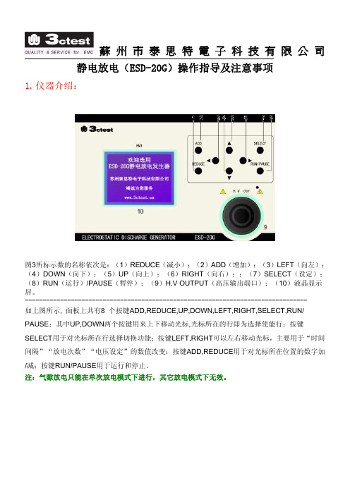
蘇州市泰思特電子科技有限公司静电放电(ESD-20G)操作指导及注意事项1.仪器介绍:图3所标示数的名称依次是:(1)REDUCE(减小);(2)ADD(增加);(3)LEFT(向左);(4)DOWN(向下);(5)UP(向上);(6)RIGHT(向右);;(7)SELECT(设定);(8)RUN(运行)/PAUSE(暂停);(9)H.V OUTPUT(高压输出端口);(10)液晶显示屏。
--------------------------------------------------------------------------------如上图所示, 面板上共有8 个按键ADD,REDUCE,UP,DOWN,LEFT,RIGHT,SELECT,RUN/ PAUSE;其中UP,DOWN两个按键用来上下移动光标,光标所在的行即为选择使能行;按键 SELECT用于对光标所在行选择切换功能;按键LEFT,RIGHT可以左右移动光标,主要用于“时间间隔”“放电次数”“电压设定”的数值改变;按键ADD,REDUCE用于对光标所在位置的数字加/减;按键RUN/PAUSE用于运行和停止。
注:气隙放电只能在单次放电模式下进行,其它放电模式下无效。
2.做ESD测试时 主要操作步骤:第一步:打开主机电源。
第二步:选择放电模式,接触放电或空气放电。
第三步:若选择接触放电(选用尖锥形的放电电极),极性切换选择正压或者负压。
第四步:若切换放电极性,只有在高压上电选择“否”的情况下才可以切换极性。
否则,切换不了。
第五步:四种放电模式,有单次放电、设定放电、自动放电、20PPS放电。
四种模式可任意选择。
第六步:若选择单次放电,高压上电选择选择“是”,选择好所需要的测试电压,按运行键RUN 进行测试,扣动一次枪击开关就放一次电,放电的速率跟手扣动枪击的快慢有关,扣的快,打的快,扣的慢,打的慢。
一般建议近1秒扣动一次枪击开关(这样接近标准)。
航天器高压太阳电池阵列ESD_检测用柔性天线传感器

Vol. 40, No. 5航 天 器 环 境 工 程第 40 卷第 5 期492SPACECRAFT ENVIRONMENT ENGINEERING2023 年 10 月https:// E-mail: ***************Tel: (010)68116407, 68116408, 68116544航天器高压太阳电池阵列ESD检测用柔性天线传感器张国治1,汪令仪1,张翰霆1,冯 娜2,王 海2,张晓星1*(1. 湖北工业大学 新能源及电网装备安全检测湖北省工程研究中心,武汉 430068;2. 北京东方计量测试研究所,北京 100094)摘要:为完善地球同步轨道(GEO)航天器静电放电(ESD)风险评估手段,文章根据空间ESD辐射电磁波频带特性,利用三维电磁场仿真软件ANSYSS HFSS,采用矩形贴片天线等效技术、梯形地平面技术和CPW馈线指数渐近线化技术开展航天器高压太阳电池阵列ESD检测用柔性天线传感器研究。
采用聚酰亚胺(PI)作为柔性天线基底,其厚度为0.28 mm;柔性天线在弯曲半径分别为100、300、500 mm 以及不弯曲条件下,300 MHz~2 GHz频带范围电压驻波比(VSWR)小于3,其中在650 MHz~2 GHz 频段范围VSWR小于2。
通过搭建的ESD模拟试验平台对传感器的电磁脉冲(EMP)信号检测性能进行实测分析,结果表明传感器能够有效地检测到高压太阳电池阵列表面的ESD EMP信号,具有用于航天器ESD故障预警的潜力。
关键词:航天器;高压太阳电池阵列;静电放电;柔性天线传感器;电磁脉冲检测;单极子天线中图分类号:V520.6; O441.5文献标志码:A文章编号:1673-1379(2023)05-0492-09 DOI: 10.12126/see.2022120Flexible antenna sensor for ESD detection ofspacecraft high voltage solar cell arrayZHANG Guozhi1, WANG Lingyi1, ZHANG Hanting1, FENG Na2, WANG Hai2, ZHANG Xiaoxing1*(1. Hubei Engineering Research Center for Safety Monitoring of New Energy and Power Grid Equipment, Hubei University ofTechnology, Wuhan 430068, China; 2. Beijing Orient Institute of Measurement and Test Organization, Beijing 100094, China) Abstract: In order to improve the electrostatic discharge (ESD) risk assessment method for geosynchronous orbit (GEO) spacecraft, research on flexible antenna sensors for spacecraft ESD radiation detection were carried out in this article. Based on the frequency band characteristics of space ESD radiation electromagnetic wave, the means applied included the three-dimensional electromagnetic field simulation software ANSYSS HFSS, the equivalent technology of rectangular patch antenna, the trapezoidal ground plane technology and the CPW feeder exponential asymptotic technology. Polyimide (PI) was used as the base of the flexible antenna, and its thickness was 0.28 mm. The voltage standing wave ratio (VSWR) was less than 3 in the 300 MHz to 2 GHz frequency band range when the bending radius was 100, 300, 500 mm and no bending, of which the VSWR was less than 2 in the 650 MHz to 2 GHz frequency band range. The electromagnetic pulse (EMP) signal detection performance was measured and analyzed by the ESD simulation test platform. The results show that the designed antenna can detect ESD EMP signal effectively, with the potential to be used for spacecraft ESD fault warning.Keywords: spacecraft; high voltage solar cell array; ESD; flexible antenna sensor; EMP detection; monopole antenna收稿日期:2022-11-07;修回日期:2023-09-17基金项目:国家自然科学基金项目(编号:52107144);湖北省教育厅科技项目(编号:Q20211401)引用格式:张国治, 汪令仪, 张翰霆, 等. 航天器高压太阳电池阵列ESD检测用柔性天线传感器[J]. 航天器环境工程, 2023, 40(5): 492-500ZHANG G Z, WANG L Y, ZHANG H T, et al. Flexible antenna sensor for ESD detection of spacecraft high voltage solar cell array[J]. Spacecraft Environment Engineering, 2023, 40(5): 492-5000 引言随着航天技术的快速发展,高压太阳电池阵列作为航天器的主电源,其对运行安全性的要求越来越高[1-2],100 V及以上的高压电池阵列已经普遍应用于地球同步轨道(GEO)航天器。
NSG 435 ESD Simulator User Manual

1NSG 435 ESD SIMULATORUSER MANUAL5.4 Air/Contact-discharge 28 5.5 Voltage 29 5.6 Polarity 30 5.7 Repetition frequency 31 5.8 Counter 31 5.9 Preselect counter 32 5.10 Automatic polarity switching 34 5.11 Continuous operation 375.12 Storing voltage settings 396 Test procedures 41 6.1 Standard-conforms procedures 416.2 Other conditions 417 Verification of the pulse data 438 Maintenance 44 8.1 Servicing 44 8.2 Calibration 44 8.3 Exchanging the R/C network 47 8.3.1 Derating of pulse repetition at increased capacitance 49 8.4 Repairs 508.5 Disposal 509 Declaration of Conformity CE 5110 Technical specifications 5211 ESD standards 5412 Warranty 5513 Odering information 5614 Addresses 57discharge network (exchangeable)measuring electronicshigh voltage relaypolarity changeovertrigger connection Test finger (exchangeable)Earth cableconnectionPulse triggerExchangeablebattery packTripod bushUNC1/4-20HandgripF1 Toggle between air and contact-discharge (and vice versa) Increment voltage and counterF2 Activation of voltage settingDecrement voltage and counterF3 Polarity switching:Selection of pre-programmed test levelsPreselect counter on/offF4 Selection of discharge mode:Single discharge Repetitive discharge at 0.5, 1, 5, 10, 20, 25 Hzfor air-dischargeRepetitive discharge at 0.5, 1, 5, 10 Hz for contact-dischargeAutomatic polarity switchingStorage of programmed test levelsF5 Resets the counterReturn from second functionNSG 435 ESD simulatorposes.The handgrip adapter is an integral part of this power supply unit. It contains electrical components that are necessary for this mode of operation. It is not per-missible to operate the NSG 435 with a power supply unit from another system.The power supply unit can be used on all common AC mains supplies without having to make any adjustments, thus:80 to 240 V (50/60 Hz) with 3-pin IEC connectorMatching 3-core mains cable20NSG 435 ESD simulator The power supply unit must be connected to a mains outlet having a protectiveearth.The protective earth connection does not replace the earth cable for the opera-tion of the NSG 435. To ensure safe and valid test operation the earth cable must be correctly connected as the pulse return path in every case.The mains power supply unit is constructed in conformity with the relevant safety standards and carries the appropriate test symbol.3.3.5 Discharge networksThe basic set contains a discharge network and test fingers that conforms to IEC/EN 61000-4-2, Ed. 1.2:2001.Alternative networks can be installed for testing in accordance with other standards.The discharge network and test fingers form a mutually matched combination. They are labeled with a corresponding INA number. The specified pulse data are only achieved while this combination is maintained.Several combinations are given in the order list. The C and R values of the discharge network can also be specified for other applications.Networks conforming to other standards can be built upon request. The speci-fications of the standard must be fully defined.Exchanging the discharge network is described in section «Exchanging the R/C network».The normal remote trigger unit consists of a «triggerbox» and 5 m (197 “) of optical cable. The remote trigger works in parallel with the «trigger-button» on the NSG 435. Pulse triggering, or the on/off switching in the case of repetitive discharges, can be effected by a push-button or an electrical signal applied to the triggerbox.The electrical signal at the BNC connector must fulfill the following condi tions:On: V = 2.4...10 V, I >2 mA, t >10 msOff: V <0.8 VRepetition rate: <5 HzThe remote trigger is powered by a conventional 9 volt battery. The current consumption is so low that a battery switch has been dispensed with. If NSG 435 provided with two optical connectors connect the optical cable to the blue terminal.It is recommended to remove the battery if the unit is not going to be used forMounting flangeContact surfaceThe measurement adapter type MD 101 as per informative annex B of IEC/EN 61000-4-2 serves to verify pulse amplitudes and pulse shapes. It is designed for mounting in the side wall of a Faraday cage in which an oscilloscope has been installed. This measurement adapter, also known as a «Pellegrini-Target» has the flat impedance curve to well over 1 GHz that is necessary for the purpose. Use of this adapter is only worthwhile in conjunction with a test rig that is laid out in strict conformity with the relevant standard (see section 7).24NSG 435 ESD simulatorSwitch the simulator on with the main switch.A display appears in the window showing values representing the status of the instrument before it was last switched off.A typical set of values might look like this:The instrument performs audible switching functions for a while that result from various self-tests and calibration procedures.High voltage generation is activated by pressing and holding the trigger button. By bringing the test finger close to the earthing point an discharge occurs which is acknowledged acoustically and the display shows the effective discharge voltage in a frame. (This applies under the following conditions: air-discharge, single-pulse, preselect counter off).The instrument is now ready to use.26NSG 435 ESD simulatorThe instrument is ready for use immediately after the execution of a self-testand calibration procedure.Press and hold the trigger button to activate the high voltage generation. The active high voltage state is shown on the display by the “kV” indication blink-ing.The measured value of the breakdown voltage in air-discharge mode will be displayed. Differentiation from the display of the set value is made by the frame around the kV readings.The effective discharge voltage depends on various factors such as the distance to the discharge point, speed of approach, nature of the EUT, etc.In the case of a contact-discharge this measurement is not carried out since only a discharge current can occur.The instrument switches itself off automatically after a period of 30 minutes of non-use although the parameters that have been set will remain stored in memory.The change to contact-discharge is prevented if:The voltage set for this operating mode is too high, i.e. over 9 kVThe repetition frequency set for this operating mode is too high, i.e.over 10 pulses/sThe instrument notifies the error with a beep and the erroneous setting blinks for 5 s.When working with fixed voltage levels, the relevant value is automatically loaded upon toggling between the air/contact-discharge mode.12Free setting Call stored values level 1-4(4 values each for air-dischargeand contact discharge) Pressing F1 or F2 raises or lowers Press F3 to select the four stored the voltage respectively in steps of voltage values in each case. 100 V. Pressing the buttons (To change a stored value, see continuously changes the voltage section 5.12).level with increasing rapidity.30NSG 435 ESD simulatorPress F5 to return to the starting menu level. (This return will also be madeautomatically after about 10 s).5.6 PolarityF3 toggles between positive and negative polarity. The sign shown in the displayalters correspondingly.In the SINGLE mode a discharge is released each time the trigger button is pressed. The discharge is confirmed by a beep. In the REPETITIVE mode dis charges are released at the chosen rate for as long as the trigger button remains pressed (no acoustic confirmation).32NSG 435 ESD simulatorF5 sets the counter either back to 0000 or to the preset value if the preselect counter mode has been chosen.Pressing F5 a second time causes a branch to the preselect counter menu.5.9 Preselect counterA specified number of discharges (0...9999) can be pre-programmed with this function. These can then be triggered single by hand or automatically.F5 first resets the counter then, when pressed a second time, branches into the preselect counter menu.F3 switches the preselect counter operation on and off (PRESELECT ON/OFF). Use F1 and F2 to raise or lower the preset value. Keeping either button pressed causes the change to occur with increasing rapidity.34NSG 435 ESD simulatorPress F5 to return to the original menu level. (This return also occurs automati-cally after about 10 s)The preselect counter mode can be used with either single or with repetitive discharges.Each time there is a discharge the counter content is decremented by 1.In the repetitive mode the discharge sequence is started when the trigger button is first pressed and is halted when the button is pressed a second time. The sequence can be continued by pressing it again.Pulse triggering is terminated when the counter content reaches 0000.F5 reloads the preselect counter with the original value.Once the counter reaches 0000 and the procedure has been stopped, the counter can also be reloaded with the original value again and the test sequence started anew simply by pressing the trigger button.5.10 Automatic polarity switchingThe IEC standards call for equal quantities of positive and then negative dis-charges to be applied to a test point. The NSG 435 can execute this function automatically.The automatic polarity switch operates in conjunction with the preselect counter.F5 branches into the preselect counter menu.F4 switches the function «Automatic polarity change» on and off (Precondition: PRESELECT ON). The active state is shown by the polarity sign in front of the voltage alternating on the display.36NSG 435 ESD simulatorUse F5 to return to the original menu level. (This return also occurs automatically after about 10 s). The «Automatic polarity change» function is identified by «ALT.POL.» over F4 and +/- over F3.The instrument switches over from positive to negative polarity once half of the preset number of pulses has been released (the sign on the display changes).This automatic function works in both the single pulse mode as well as with repetitive discharges.Reinitialize the operation in single pulse mode after each cycle. Reset the counter and select the counter menu again (press F5 three times).Select the repetition frequency in the basic menu with F4. By F5 branch into the preselect counter menu.38NSG 435 ESD simulatorHold F2 down until the counter content is 0000. Press F2 again to activate continuous operation. The display shows - - - -.Use F5 to return to the original menu level.Switching off continuous operation:By F5 branch into the preselect counter menu. Press F1 or F2. The counter shows 0000 or 9999 respectively. Continuous operation is switched off.Use F5 to return to the original menu level.5.12 Storing voltage settingsPre-programmed discharge voltage values can be stored in four memory loca-tions for both air and contact-discharges. As delivered, the instrument has the test levels set according to IEC/EN 61000-4-2, Ed. 1.2:2001.The values stored in memory can be altered arbitrarily.Level Test voltage contact-discharge 1234 2 kV 4 kV 6 kV 8 kV40NSG 435 ESD simulator Press F4 and a memory location (1 ... 4) appears over F3.Use F3 to specify the required memory location. Press F4 again and the value is stored.Use F5 to return to the original menu level.Set the required voltage with F1 or F2.Range for air: 0.2 ... 16.5 kVRange for contact: 0.2 ...9 kVThe «LEVEL» indication shown over F3 disappears. «STORE» appears over F4.simulator46 537A yellowB black8C yellow/green48NSG 435 ESD simulator Procedure:1 Switch the instrument off2 Remove the earth cable3 Take out the battery4 Unscrew the test finger5 Pull out the trigger button6 Remove the rear cover(the cover locks into 3 notches in the housing on both sides. The cover can be removed by carefully lifting it at the points where the notches are and gradually sliding it back).7 Lay the instrument on its side and remove the screws8 Remove the screw in the printed circuit board9 Remove the upper part of the housing with a rocking movement 10 Note the arrangement of the wiring11 Release the network connecting screws in the given order12 Remove the network13 Insert the replacement network14 Firmly screw the color-coded network connections into place as shown in the illustration15 Take care with the placement of the wires so that none becoming trapped while re-assembling the generator16 Carefully screw the upper part of the housing back into place17 Continue re-assembly in the reverse order of points 8 .. 1 above (attach the test finger belonging to the set!)18 Check the operation of the generator by observing the spark-gap (the high voltage generator adjusts itself automatically to the newnetwork)19 If in doubt, a voltage check can be carried out as given in section 8.220 A calibration measurement is not normally necessary50NSG 435 ESD simulator 8.4 RepairsRepair work is to be executed exclusively by authorized Teseq repair depart-ments. Only original replacement parts and accessories are to be used.Do not continue to use the instrument in the event of mechanical damage occurring. The molded housing also performs insulating and protective func-tions which are only assured as long as it is in its original condition. A damaged instrument should be returned without delay to a Teseq service centre.8.5 DisposalThe following list shows the principal materials that are used in the construction of the NSG 435. The relevant national regulations are to be observed when disposing of the instrument.Item Material RemarkHousing Control unit LCD-display LCD-window Chassis plate HV unit/network HV relay Test finger Battery Charger Carrying case ABS with glass-fiberEpoxy circuit board with SMD componentsGlassAcrylicGalvanized steelPolyurethane block with electr.components and copper wireVarious metals, ceramicvarious insulating MagerialsBrass, plastics, electrical componentsNickel-metal hybrid (>2002) ABS hosuing Epoxy circuit board ABS housing with transformer, PCB with electr, componentsPolyethyleneObserve any specialregulations regardingdisposal of Ni-MHs。
esd静电放电抗扰度检测方法与检测标准

ESD静电放电是指在两个接触或接近的物体间由于静电电荷失去平衡而发生的放电现象,通常称为静电击。
在现代电子产品制造和使用过程中,静电放电对电子产品的影响极其重要,甚至可能对产品的性能和寿命产生严重影响。
对静电放电抗扰度检测方法和检测标准的研究和制定显得尤为重要。
一、ESD静电放电抗扰度检测方法1. 传统方法传统的ESD静电放电抗扰度检测方法主要包括人体静电放电(HBM)、机器模拟静电放电(MM)和车间模拟静电放电(CDM)三种方式。
其中,HBM是通过人体与电气设备或系统之间的接触来模拟电气设备在实际应用中的静电放电,MM是通过模拟电气设备在实际应用中的机器间的接触来模拟静电放电,CDM则是通过模拟电气设备在实际应用中的车间之间的接触来模拟静电放电。
这些方法在一定程度上可以模拟实际应用环境中的静电放电,但是在实际应用中的适用性和准确性有待进一步验证。
2. 新兴方法随着科学技术的不断进步和电子产品的不断更新换代,新兴的ESD静电放电抗扰度检测方法也在不断涌现。
基于纳米技术的ESD静电放电抗扰度检测方法,通过利用纳米技术的特殊性能,可以更加精准地模拟和检测实际应用环境中的静电放电,提高了检测的准确性和可靠性。
还有基于仿生学的ESD静电放电抗扰度检测方法,通过模拟自然界中生物体对静电放电的响应机制,可以提高电子产品对静电放电的抗扰度。
二、ESD静电放电抗扰度检测标准1. 国际标准目前,国际上对ESD静电放电抗扰度检测标准的制定已经相对成熟,在国际电工委员会(IEC)和国际标准化组织(ISO)已经有了相关的标准,如IEC 61340系列标准和ISO 10605标准等。
这些标准主要针对静电放电的发生原理、检测方法、抗扰度要求等进行了详细规定,对于全球范围内的电子产品生产和使用具有重要指导意义。
2. 国内标准在国内,我国电子技术标准化研究院(CESI)和我国合格评定国家认可委员会(CNAS)等机构也已经制定了相关的ESD静电放电抗扰度检测标准,如GB/T 16927标准等。
HBM_MM_CDM静电放电模拟器测试使用方法
HBM、MM&CDM静电放电模拟器静电放电模拟器目 录目 录 (1)1.概述 (2)2.基本设置 (2)2.1使用前的准备 (2)2.2放电重复时间(REPEAT TIME)设置 (3)2.3静电放电次数(ESD NUMBER)设置 32.4 测试电压的调节(ADJ) (4)3HBM试验 (4)3.1 HBM OUT与测试 (4)3.2 HBM试验电压等级 (6)3.3 HBM试验管脚组合 (8)3.4 HBM敏感度分类 (11)3.5HBM测试注意事项124. MM试验 (13)4.1 MM OUT的输出与选择 (13)4.1.1 OUT接线与MM选择 (13)4.1.2输出电压、正负极性的设置 (13)4.2 MM试验电压大小与极性 (13)4.3 MM试验管脚组合 (14)4.4.MM静电试验电压和极性的选择154.5选择静电放电重复频率 (15)4.6 MM的ESDS分类 (16)4.7 MM试验的特点与注意事项 (16)4.8. MM与HBM放电的比较(相同电压下,哪个损坏程度大? (16)5 CDM试验 (18)5.1 CDM充电的2种常用方法D-CDM与F-CDM (18)5.1.1 直接充电方法D-CDM (18)5.1.2 感应充电方法F-CDM (18)5.1.3 两种带电方法接线的比较 (19)5.2 CDM的设置与接线 (19)5.3 选择CDM静电试验电压和极性 (20)5.4 CDM试验电压等级 (20)5.5 CDM试验特点与注意事项 (20)5.6 CDM的放电 (21)5.7 CDM敏感度分类 (22)6 使用操作注意事项 (23)7 主要技术指标 (24)8 技术支持与售后服务 (24)9. 定期校准 (24)ESD-china的优势..............................................................................................................错误!未定义书签。
esd测试等级标准

esd测试等级标准ESD测试等级标准是确定电子产品和器件静电敏感性的一种方式。
ESD(Electrostatic Discharge)即静电放电,是指在两个电势不同的物体之间会产生电荷交换的现象。
静电放电可能对电子产品和器件造成损害,因此对其进行测试和评估是非常重要的。
静电放电可能导致电子产品和器件的故障和失效。
这些故障和失效可能会在生产过程中产生,或者在产品正常使用中发生。
比如,当一个人穿着带静电的衣物触摸到电子产品或器件时,会产生静电放电,并可能导致产品损坏。
为了减少这种损害的发生,ESD测试等级标准被制定出来。
以下是一些常用的ESD测试等级标准:1. IEC 61000-4-2:这个标准是国际电工委员会(IEC)制定的,用于评估电子设备耐受不同等级ESD的能力。
该标准根据静电放电的电压等级将电子设备分为不同的等级,包括2KV、4KV、8KV和15KV。
2. ANSI/ESD S20.20:这个标准是美国国家标准化协会(ANSI)和电子行业协会(ESDA)联合制定的,用于评估和管理电子设备防静电措施的有效性。
该标准定义了不同的ESD控制区域,并规定了不同区域内的静电放电限制。
3. MIL-STD-883:这个标准是美军标准之一,用于评估和测试电子器件的可靠性和耐受能力。
该标准包括了多个测试方法和等级,其中包括对ESD的测试。
4. JEDEC JESD22:这个标准是电子设备供应商联盟(JEDEC)制定的,用于评估和测试电子器件的可靠性和耐受能力。
其中包括了多个测试方法和等级,包括ESD测试。
以上只是一些常见的ESD测试等级标准,不同国家、不同行业和不同应用领域可能会有所不同。
同时,ESD测试等级标准通常还会包括测试方法和规程,以确保测试的准确性和一致性。
ESD测试等级标准的制定和遵守对于保护电子产品和器件的可靠性和耐受能力至关重要。
遵守这些标准可以帮助制造商和供应商确保其产品在生产过程中减少ESD相关的损坏,并提高其在使用过程中的可靠性。
- 1、下载文档前请自行甄别文档内容的完整性,平台不提供额外的编辑、内容补充、找答案等附加服务。
- 2、"仅部分预览"的文档,不可在线预览部分如存在完整性等问题,可反馈申请退款(可完整预览的文档不适用该条件!)。
- 3、如文档侵犯您的权益,请联系客服反馈,我们会尽快为您处理(人工客服工作时间:9:00-18:30)。
Teseq推出增强型NSG 438 静电放电(ESD)模拟器
特测, 美国AMETEK (阿美特克)集团Compliance Test Solutions(电磁兼容事业部)旗下子公司, 全球领先的电磁兼容(EMC)发射及抗干扰测试仪器及测试系统的开发商,宣布推出带有全新彩色触摸式显示屏的增强型NSG 438静电放电(ESD)模拟器,用户可以直接在放电枪上进行参数设置与功能切换。
作为市场上首款配备彩色触摸式显示屏的静电放电(ESD)模拟器,该款产品为用户提供了更好的视角和更简便的操作。
同时,特测的NSG 437静电放电(ESD)模拟器也包含这一全新的独特功能。
功能升级后的NSG 438易于使用,在市场上所有ESD模拟器中拥有最长的电池操作时间,电池一次充电后可在30 kV下进行超过30,000次放电。
此外,设备中还内建有显示ESD放电类型和放电次数的特殊活动日志,能够帮助使用者通过浏览触摸式显示屏查看已完成的测试项目和测试时间。
NSG 438适用于汽车与其组件的ESD测试,以及所有消费类电子产品、家用电器、信息技术、医疗与工业设备的ESD测试。
NSG 438提供了可选配的内置式放电开关电路,用于泄放常规产品以及未接地被测设备(EUT)在进行ESD测试时的残留电压。
NSG 438的参数设置包括极性选择、可自由调节的脉冲重复率、计数器功能以及放电检测。
即使在放电电压设置到最高30 kV的情况下,仍然可以在预定范围内任意设定测试参数。
此款装置符合ISO 10605测试标准,确保了对被测设备进行测试的过程安全、高效,能满足包括IEC 61000-4-2在内所有来自汽车、商业和工业标准的要求。
为了更高的安全性,设备还包含有紧急停机开关。
主要特点
· 放电电压:200 V至30 kV(最小调节单位:100 V)
· 电池寿命:30 kV下超过30,000次放电
· 可方便、快速地进行互换的放电网络
· 含有150 pF/330 Ohm放电网络
· 超过60个可选放电网络并可根据用户需求定制
· 三种运行模式:单次、重复和随机
· 内建ISO自校准功能
关于特测:
作为美国AMETEK(阿美特克)集团Compliance Test Solutions(电磁兼容事业部)旗下子公司,特测(Teseq)是全球领先的汽车、消费类和工业电子产品、电信、医疗、国防和航天业电磁兼容发射及传导干扰用仪器与系统开发商,AMETEK(阿美特克)集团Compliance Test Solutions(电磁兼容事业部)旗下拥有Teseq、IFI、MILMEGA和EM Test四大品牌,提供全球最全面的电磁兼容辐射和抗干扰测试系统。
其强大的全球服务网络和经过本地认证的校准实验室确保了快速的校准和修理周转。
特测(Teseq)的母公司AMETEK是全球顶尖的电子仪器和机电设备制造商,年销售额达36亿美元。