压力传感器的毕业设计英语论文
压力传感器论文压电传感器论文

压力传感器论文压电传感器论文一种用于压力传感器的温度控制系统设计摘要:针对SiC高温MEMS压力传感器易受温度影响,产生零点漂移、测量误差增大等问题,设计了一种温度控制系统,根据科恩-库恩公式建立了系统的数学模型,采用参数自整定PID控制算法,克服了纯PID 控制有较大超调量的缺点,实现了一个温度控制系统。
利用Matlab仿真软件的Similink模块建立系统的仿真模型,通过仿真和测试验证系统满足设计要求。
解决了大温度范围下压力传感器难以补偿的问题,使得压力传感器在高温环境下的应用得以实现,提高了压力传感器的稳定性。
关键词:MEMS; 压力传感器; 温度控制; 零点漂移Design of Temperature Control System for Pressure Sensors GUO Jiang(College of Information Engineering, Southwest University of Science and Technology, Mianyang 621010, China) Abstract: A temperature control system for the SiC MEMS pressure sensor is designed as the pressure sensor is susceptible to high temperature, and easy to result in zero drift, and measurement error increase. A mathematical model for the system is established according to Cohen-Coon formula. And finally a temperature control system is achieved with theparameter self-tuning PID control algorithm to overcome the shortcoming of a large overshoot adjustment of pure PID control. The Similink module simulation model was set up by the Matlab Simulation software system. The simulation and testing verifies that the system can meet the design demands. The pressure sensor is hard to be compensated within a large temperature range is solved, with which the application of the pressure sensor in high temperature environments is achieved and the stability of the pressure sensor is improved.Keywords: MEMS; pressure sensor; temperature control; zero drift0 引言在微电子器件领域,针对SiC器件的研究较多,已经取得了较大进展,而在MEMS领域针对SiC器件的研究仍有许多问题亟待解决。
毕业设计(论文)-基于can总线的智能压力传感器[管理资料]
![毕业设计(论文)-基于can总线的智能压力传感器[管理资料]](https://img.taocdn.com/s3/m/67abcd26195f312b3069a5a2.png)
南京工业大学毕业设计任务书学院专业年级学生姓名任务下达日期:2005 年12 月20 日毕业设计日期:2006 年2月20 日至2006 年 6 月20日毕业设计题目:基于CAN总线的智能压力传感器毕业设计专题题目:毕业设计主要内容和要求:1、了解目前压力监测装置的应用现状及发展趋势;2、了解CAN总线的原理、特点;3、设计一种基于CAN总线的智能压力传感器,使之具有数据存储、显示、报警、修改上下限报警值以及通信功能;要求硬件配置方面包括微控制器模块、压力传感器模块、数码管显示模块、通信模块及仪表的抗干扰措施的设计;软件方面包括初始化模块、数据采集模块、数据处理模块、LED显示模块、通信模块及控制模块等相应程序以及总程序的编写; 最后进行软硬件仿真调试。
院长签字:指导教师签字:指导教师评语(①基础理论及基本技能的掌握;②独立解决实际问题的能力;③研究内容的理论依据和技术方法;④取得的主要成果及创新点;⑤工作态度及工作量;⑥总体评价及建议成绩;⑦存在问题;⑧是否同意答辩等):成绩:指导教师签字:年月日评阅教师评语(①选题的意义;②基础理论及基本技能的掌握;③综合运用所学知识解决实际问题的能力;③工作量的大小;④取得的主要成果及创新点;⑤写作的规范程度;⑥总体评价及建议成绩;⑦存在问题;⑧是否同意答辩等):成绩:评阅教师签字:年月日南京工业大学毕业设计答辩及综合成绩摘要针对目前我国煤炭安装生产中液压支架监测系统传统测量方法存在的种种不足,从煤矿综合机械化采煤的特殊环境出发,提出了一种基于CAN总线的智能压力传感器。
本文针对总线型仪表的要求,选用了PIC系列的带有CAN总线接口的18F458单片机,开发了一种基于CAN总线的智能压力传感器。
本论文主要介绍了:首先对CAN总线进行详细的介绍;然后在硬件配置方面加以介绍,包括微控制器模块、传感器模块、显示模块、通信模块;接着从软件方面加以介绍,包括初始化模块、A/D转换模块、修改报警上下限模块、LED显示模块、通信模块以及软件抗干扰措施的编写,即给出了系统总的程序流程图和各子程序流程图。
Sensor-technology传感器技术大学毕业论文外文文献翻译及原文

毕业设计(论文)外文文献翻译文献、资料中文题目:传感器技术文献、资料英文题目:Sensor-technology文献、资料来源:文献、资料发表(出版)日期:院(部):专业:班级:姓名:学号:指导教师:翻译日期: 2017.02.14Sensor technologyA sensor is a device which produces a signal in response to its detecting or measuring a property ,such as position , force , torque , pressure , temperature , humidity , speed , acceleration , or vibration .Traditionally ,sensors (such as actuators and switches )have been used to set limits on the performance of machines .Common examples are (a) stops on machine tools to restrict work table movements ,(b) pressure and temperature gages with automatics shut-off features , and (c) governors on engines to prevent excessive speed of operation . Sensor technology has become an important aspect of manufacturing processes and systems .It is essential for proper data acquisition and for the monitoring , communication , and computer control of machines and systems .Because they convert one quantity to another , sensors often are referred to as transducers .Analog sensors produce a signal , such as voltage ,which is proportional to the measured quantity .Digital sensors have numeric or digital outputs that can be transferred to computers directly .Analog-to-coverter(ADC) is available for interfacing analog sensors with computers .Classifications of SensorsSensors that are of interest in manufacturing may be classified generally as follows:Machanical sensors measure such as quantities aspositions ,shape ,velocity ,force ,torque , pressure , vibration , strain , and mass .Electrical sensors measure voltage , current , charge , and conductivity .Magnetic sensors measure magnetic field ,flux , and permeablity .Thermal sensors measure temperature , flux ,conductivity , and special heat .Other types are acoustic , ultrasonic , chemical , optical , radiation , laser ,and fiber-optic .Depending on its application , a sensor may consist of metallic , nonmetallic , organic , or inorganic materials , as well as fluids ,gases ,plasmas , or semiconductors .Using the special characteristics of these materials , sensors covert the quantity or property measured to analog or digital output. The operation of an ordinary mercury thermometer , for example , is based on the difference between the thermal expansion of mercury and that of glass.Similarly , a machine part , a physical obstruction , or barrier in a space can be detected by breaking the beam of light when sensed by a photoelectric cell . A proximity sensor ( which senses and measures the distance between it and an object or a moving member of a machine ) can be based on acoustics , magnetism , capacitance , or optics . Other actuators contact the object and take appropriate action ( usually by electromechanical means ) . Sensors are essential to the conduct of intelligent robots , and are being developed with capabilities that resemble those of humans ( smart sensors , see the following ).This is America, the development of such a surgery Lin Bai an example, through the screen, through a remote control operator to control another manipulator, through the realization of the right abdominal surgery A few years ago our country theexhibition, the United States has been successful in achieving the right to the heart valve surgery and bypass surgery. This robot has in the area, caused a great sensation, but also, AESOP's surgical robot, In fact, it through some equipment to some of the lesions inspections, through a manipulator can be achieved on some parts of the operation Also including remotely operated manipulator, and many doctors are able to participate in the robot under surgery Robot doctor to include doctors with pliers, tweezers or a knife to replace the nurses, while lighting automatically to the doctor's movements linked, the doctor hands off, lighting went off, This is very good, a doctor's assistant.Tactile sensing is the continuous of variable contact forces , commonly by an array of sensors . Such a system is capable of performing within an arbitrarythree-dimensional space .has gradually shifted from manufacturing tonon-manufacturing and service industries, we are talking about the car manufacturer belonging to the manufacturing industry, However, the services sector including cleaning, refueling, rescue, rescue, relief, etc. These belong to the non-manufacturing industries and service industries, so here is compared with the industrial robot, it is a very important difference. It is primarily a mobile platform, it can move to sports, there are some arms operate, also installed some as a force sensor and visual sensors, ultrasonic ranging sensors, etc. It’s surrounding environment for the conduct of identification, to determine its campaign to complete some work, this is service robot’s one of the basic characteristicsIn visual sensing (machine vision , computer vision ) , cameral optically sense the presence and shape of the object . A microprocessor then processes the image ( usually in less than one second ) , the image is measured , and the measurements are digitized ( image recognition ) .Machine vision is suitable particularly for inaccessible parts , in hostile manufacturing environments , for measuring a large number of small features , and in situations where physics contact with the part may cause damage .Small sensors have the capability to perform a logic function , to conducttwo-way communication , and to make a decisions and take appropriate actions . The necessary input and the knowledge required to make a decision can be built into a smart sensor . For example , a computer chip with sensors can be programmed to turn a machine tool off when a cutting tool fails . Likewise , a smart sensor can stop a mobile robot or a robot arm from accidentally coming in contact with an object or people by using quantities such as distance , heat , and noise .Sensor fusion . Sensor fusion basically involves the integration of multiple sensors in such a manner where the individual data from each of the sensors ( such as force , vibration , temperature , and dimensions ) are combined to provide a higher level of information and reliability . A common application of sensor fusion occurs when someone drinks a cup of hot coffee . Although we take such a quotidian event for granted ,it readily can be seen that this process involves data input from the person's eyes , lips , tongue , and hands .Through our basic senses of sight , hearing , smell , taste , and touch , there is real-time monitoring of relative movements , positions , and temperatures . Thus if the coffee is too hot , the hand movement of the cup toward the lip is controlled and adjusted accordingly .The earliest applications of sensor fusion were in robot movement control , missile flight tracking , and similar military applications . Primarily because these activities involve movements that mimic human behavior . Another example of sensor fusion is a machine operation in which a set of different but integrated sensors monitors (a) the dimensions and surface finish of workpiece , (b) tool forces , vibrations ,and wear ,(c) the temperature in various regions of the tool-workpiece system , and (d) the spindle power .An important aspect in sensor fusion is sensor validation : the failure of one particular sensor is detected so that the control system maintains high reliability . For this application ,the receiving of redundant data from different sensors is essential . It can be seen that the receiving , integrating of all data from various sensors can be a complex problem .With advances in sensor size , quality , and technology and continued developments in computer-control systems , artificial neural networks , sensor fusion has become practical and available at low cost .Movement is relatively independent of the number of components, the equivalent of our body, waist is a rotary degree of freedom We have to be able to hold his arm, Arm can be bent, then this three degrees of freedom, Meanwhile there is a wrist posture adjustment to the use of the three autonomy, the general robot has six degrees of freedom. We will be able to space the three locations, three postures, the robot fully achieved, and of course we have less than six degrees of freedomFiber-optic sensors are being developed for gas-turbine engines . These sensors will be installed in critical locations and will monitor the conditions inside the engine , such as temperature , pressure , and flow of gas . Continuous monitoring of the signals from thes sensors will help detect possible engine problems and also provide the necessary data for improving the efficiency of the engines .传感器技术传感器一种通过检测某一参数而产生信号的装置。
桥式压力传感器(英文)
STRAIN GAGE
Figure 3. Pressure measuring instrumentation.
SIGNAL CONDITIONING ELECTRONICS
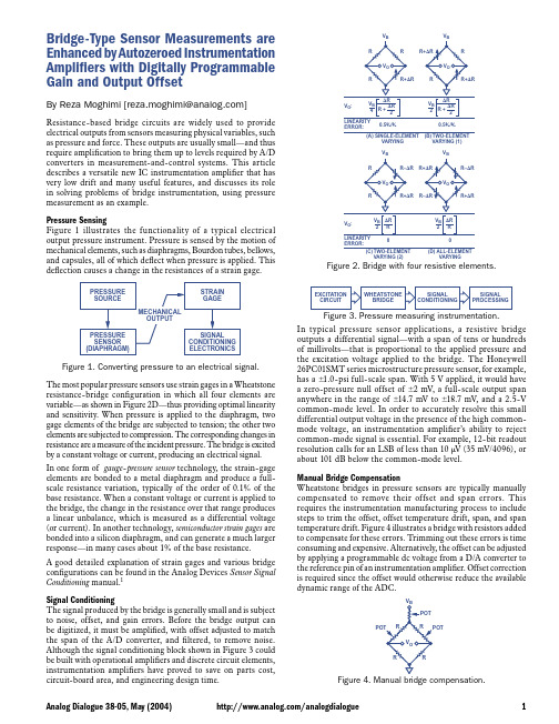
In typical pressure sensor applications, a resistive bridge outputs a differential signal—with a span of tens or hundreds of millivolts—that is proportional to the applied pressure and the excitation voltage applied to the bridge. The Honeywell 26PC01SMT series microstructure pressure sensor, for example, has a 1.0 -psi full-scale span. With 5 V applied, it would have a zero-pressure null offset of 2 mV, a full-scale output span anywhere in the range of 14.7 mV to 18.7 mV, and a 2.5-V common-mode level. In order to accurately resolve this small differential output voltage in the presence of the high commonmode voltage, an instrumentation amplifier’s ability to reject common-mode signal is essential. For example, 12-bit readout resolution calls for an LSB of less than 10 V (35 mV/4096), or about 101 dB below the common-mode level.
电气专业毕业设计--外文翻译--电容式传感器操作第一部分:基础
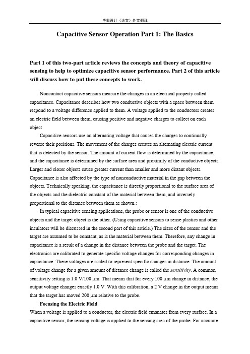
Capacitive Sensor Operation Part 1: The BasicsPart 1 of this two-part article reviews the concepts and theory of capacitive sensing to help to optimize capacitive sensor performance. Part 2 of this article will discuss how to put these concepts to work.Noncontact capacitive sensors measure the changes in an electrical property called capacitance. Capacitance describes how two conductive objects with a space between them respond to a voltage difference applied to them. A voltage applied to the conductors creates an electric field between them, causing positive and negative charges to collect on each objectCapacitive sensors use an alternating voltage that causes the charges to continually reverse their positions. The movement of the charges creates an alternating electric current that is detected by the sensor. The amount of current flow is determined by the capacitance, and the capacitance is determined by the surface area and proximity of the conductive objects. Larger and closer objects cause greater current than smaller and more distant objects. Capacitance is also affected by the type of nonconductive material in the gap between the objects. Technically speaking, the capacitance is directly proportional to the surface area of the objects and the dielectric constant of the material between them, and inversely proportional to the distance between them as shown.:In typical capacitive sensing applications, the probe or sensor is one of the conductive objects and the target object is the other. (Using capacitive sensors to sense plastics and other insulators will be discussed in the second part of this article.) The sizes of the sensor and the target are assumed to be constant, as is the material between them. Therefore, any change in capacitance is a result of a change in the distance between the probe and the target. The electronics are calibrated to generate specific voltage changes for corresponding changes in capacitance. These voltages are scaled to represent specific changes in distance. The amount of voltage change for a given amount of distance change is called the sensitivity. A common sensitivity setting is 1.0 V/100 µm. That means that for every 100 µm change in distance, the output voltage changes exactly 1.0 V. With this calibration, a 2 V change in the output means that the target has moved 200 µm relative to the probe.Focusing the Electric FieldWhen a voltage is applied to a conductor, the electric field emanates from every surface. In a capacitive sensor, the sensing voltage is applied to the sensing area of the probe. For accuratemeasurements, the electric field from the sensing area needs to be contained within the space between the probe and the target. If the electric field is allowed to spread to other items—or other areas on the target—then a change in the position of the other item will be measured as a change in the position of the target. A technique called "guarding" is used to prevent this from happening. To create a guard, the back and sides of the sensing area are surrounded by another conductor that is kept at the same voltage as the sensing area itself. When the voltage is applied to the sensing area, a separate circuit applies the exact same voltage to the guard. Because there is no difference in voltage between the sensing area and the guard, there is no electric field between them. Any other conductors beside or behind the probe form an electric field with the guard instead of with the sensing area. Only the unguarded front of the sensing area is allowed to form an electric field with the target.DefinitionsSensitivity indicates how much the output voltage changes as a result of a change in the gap between the target and the probe. A common sensitivity is 1 V/0.1 mm. This means that for every 0.1 mm of change in the gap, the output voltage will change 1 V. When the output voltage is plotted against the gap size, the slope of the line is the sensitivity.A system's sensitivity is set during calibration. When sensitivity deviates from the ideal value this is called sensitivity error, gain error, or scaling error. Since sensitivity is the slope of a line, sensitivity error is usually presented as a percentage of slope, a comparison of the ideal slope with the actual slope.Offset error occurs when a constant value is added to the output voltage of the system. Capacitive gauging systems are usually "zeroed" during setup, eliminating any offset deviations from the original calibration. However, should the offset error change after the system is zeroed, error will be introduced into the measurement. Temperature change is the primary factor in offset error.Sensitivity can vary slightly between any two points of data. The accumulated effect of this variation is called linearity erro. The linearity specification is the measurement of how far the output varies from a straight line.To calculate the linearity error, calibration data are compared to the straight line that would best fit the points. This straight reference line is calculated from the calibration data using least squares fitting. The amount of error at the point on the calibration line furthest away from this ideal line is the linearity error. Linearity error is usually expressed in terms of percent of full scale (%/F.S.). If the error at the worst point is 0.001 mm and the full scale range of the calibration is 1 mm, the linearity error will be 0.1%.Note that linearity error does not account for errors in sensitivity. It is only a measure of the straightness of the line rather than the slope of the line. A system with gross sensitivity errors can still be very linear.Error band accounts for the combination of linearity and sensitivity errors. It is the measurement of the worst-case absolute error in the calibrated range. The error band is calculated by comparing the output voltages at specific gaps to their expected value. The worst-case error from this comparison is listed as the system's error band. In Figure 7, the worst-case error occurs for a 0.50 mm gap and the error band (in bold) is –0.010.Gap (mm)Expected Value (VDC)Actual Value VDC)Error (mm) 0.50 –10.000 –9.800 –0.0100.75 –5.000 –4.900 –0.0051.00 0.000 0.000 0.0001.25 5.000 5.000 0.0001.50 10.000 10.100 0.005Figure 7. Error valuesBandwidth is defined as the frequency at which the output falls to –3 dB, a frequency that is also called the cutoff frequency. A –3 dB drop in the signal level is an approximately 30% decrease. With a 15 kHz bandwidth, a change of ±1 V at low frequency will only produce a ±0.7 V change at 15 kHz. Wide-bandwidth sensors can sense high-frequency motion and provide fast-responding outputs to maximize the phase margin when used in servo-control feedback systems; however, lower-bandwidth sensors will have reduced output noise which means higher resolution. Some sensors provide selectable bandwidth to maximize either resolution or response time.Resolution is defined as the smallest reliable measurement that a system can make. The resolution of a measurement system must be better than the final accuracy the measurement requires. If you need to know a measurement within 0.02 µm, then the resolution of the measurement system must be better than 0.02 µm.The primary determining factor of resolution is electrical noise. Electrical noise appears in the output voltage causing small instantaneous errors in the output. Even when theprobe/target gap is perfectly constant, the output voltage of the driver has some small but measurable amount of noise that would seem to indicate that the gap is changing. This noise is inherent in electronic components and can be minimized, but never eliminated.If a driver has an output noise of 0.002 V with a sensitivity of 10 V/1 mm, then it has an output noise of 0.000,2 mm (0.2 µm). This means that at any instant in time, the output could have an error of 0.2 µm.The amount of noise in the output is directly related to bandwidth. Generally speaking, noise is distributed over a wide range of frequencies. If the higher frequencies are filtered before the output, the result is less noise and better resolution (Figures 8, 9). When examining resolution specifications, it is critical to know at what bandwidth the specifications apply.Capacitive Sensor Operation Part 2: System OptimizationPart 2 of this two-part article focuses on how to optimize the performance of your capacitive sensor, and to understand how target material, shape, and size will affect the sensor's response.Effects of Target SizeThe target size is a primary consideration when selecting a probe for a specific application. When the sensing electric field is focused by guarding, it creates a slightly conical field that is a projection of the sensing area. The minimum target diameter is usually 130% of the diameter of the sensing area. The further the probe is from the target, the larger the minimum target size.Range of MeasurementThe range in which a probe is useful is a function of the size of the sensing area. The greater the area, the larger the range. Because the driver electronics are designed for a certain amount of capacitance at the probe, a smaller probe must be considerably closer to the target to achieve the desired amount of capacitance. In general, the maximum gap at which a probe is useful is approximately 40% of the sensing area diameter. Typical calibrations usually keep the gap to a value considerably less than this. Although the electronics are adjustable during calibration, there is a limit to the range of adjustment.Multiple Channel SensingFrequently, a target is measured simultaneously by multiple probes. Because the system measures a changing electric field, the excitation voltagefor each probe must be synchronized or the probes will interfere with each other. If they were not synchronized, one probe would be trying to increase the electric field while another was trying to decrease it; the result would be a false reading. Driver electronics can be configured as masters or slaves; the master sets the synchronization for the slaves in multichannel systems.Effects of Target MaterialThe sensing electric field is seeking a conductive surface. Provided that the target is a conductor, capacitive sensors are not affected by the specific target material; they will measure all conductors—brass, steel, aluminum, or salt water—as the same. Because the sensing electric field stops at the surface of the conductor, target thickness does not affect the measurement中文翻译电容式传感器操作第一部分:基础 这篇文章的第一部分回顾了电容式传感器的概念和理论来帮助我们优化电容式传感器的性能。
传感器外文翻译
毕业设计(论文)外文文献翻译院系:光电与通信工程年级专业:12电子信息工程姓名:刘燊学号:1106012133附件:Advances in Sensor Technology Development指导老师评语:指导教师签名:年月日——摘自夏伟强,樊尚春传感器技术的的新发展仪器仪表学报传感器技术的新进展传感器技术是新技术革命和信息社会的重要技术基础,是一门多学科交叉的科学技术,被公认为现代信息技术的源头。
近些年,传感器技术发展很快,取得了许多新进展,尤其在气体传感器、生物传感器、视觉传感器等方面取得了很多进展。
美国麻省理工学院华人科学家张曙光领导的研究小组借助一种特殊溶液,成功地找到了大规模制造嗅觉感受器的办法;同样是麻省理工学院的研究人员利用气相色谱-质谱技术感受识别气体分子,研制出一种能对微量有毒气体做出强烈反应的微型传感器;俄罗斯科学家以从一种普通蘑菇中提取的混合物为原料,与压电石英晶振构成谐振式传感器,能够探测空气中含量极低的酚成分;日本科学家研制出能快速识别流感病毒纳米传感器,有望以纳米技术为快速识别流感病毒、乙型肝炎病毒、疯牛病病原体和残留农药等物质提供新手段;西班牙巴塞罗那自治大学研制出新型缩微DNA分析传感器,这种传感器能将分析 DNA链的时间缩短到几分钟或几小时,智能仪器与传感器技术、空间生物智能传感技术。
可以在亲子鉴定到检测遗传修饰食物的一系列化验中应用,此外还能确定新药的遗传毒性;美国国家标准与技术研究院研发出一种超灵敏微型核磁共振(NMR)传感器,该微型传感器与微流体通道并列置于一个硅芯片之上,这项技术将核磁共振的探测灵敏度提升到一个新的台阶,将在化学分析中具有广泛的应用前景。
我国传感器技术虽然与国外相比还有很大差距,但近两年也取得了一些进展和突破,诞生了一些新产品,有些在国家重大型号工程中获得应用。
如资源环境技术领域中的环境监测及环境风险评价技术、大气复合污染关键气态污染物的快速在线监测技术和大气细粒子和超细粒子的快速在线监测技术,海洋技术领域中的海洋水质污染综合参数在线监测技术和海洋金属污染物现场和在线监测技术等。
《传感器英文论文》
《电气工程及其自动化专业英语》课程论文年级专业姓名学号TransformerThe basic concept of transformerPower transformer is a kind of static electrical equipment, is used for AC voltage is a numerical (current) into a voltage value of the same frequency one or several different (current) equipment. When a winding with alternating current, is generated by the alternating magnetic flux, the alternating magnetic flux through the iron core of the magnetic effect, the AC induction electromotive force in the two secondary winding. The two induction electromotive force level and one or two times the number of winding turns the number of voltage size and number of turns is proportional to. The main function is to transmit electricity, therefore, the rated capacity is its main parameters. Rated capacity is used in a performance of power value, it is the characterization of electrical energy transmission size, with kVA or MVA said that when the rated voltage is applied to the transformer, according to it to determine under specified conditions does not exceed the rated current value of temperature riseThe development trend of transformerDistribution transformer in China usually refers to the voltage of 35kV and 10kV and below, capacity below 6300kVA power transformer terminal user directly to the power supply. At present, the national online operation of distribution transformer total power loss is about 41100000000kWh, accounting for about 3.16% of total generating capacity in 2000. Although the distribution transformer is high-efficiency equipment (95-99%), but because of the large quantity and fixed the no-load power consumption, transformer efficiency even small improvements can also considerable energy saving and reduction of greenhouse gas emissions, so its itself there is a huge energy saving potentialIn the late 90, the speed of the development of industry of our country distribution transformer faster. Since 1997, due to urban and rural power grid renovation project of the pull, the power transformer industry has maintained a good momentum of development. Power transformer output growth of 24.81% in 1999. In 2000 the power transformer production increased by 15.88%, the proportion of the number of distribution transformer increase: in 1999 the number of distribution transformer proportion rose from 34.72% in 1998 to 39.51%, an increase of 5 percentage points; in 2000 the proportion of the number of distribution transformer 36.89%. (10kV and below 6300KVA transformer output was 304099 units, 41778KVA, 35kV, 6300KVA and below transformers production was 7821 units, 9316.4KVA). Oil immersed distribution transformer equipment of urban and rural power grid renovation project selected have all realized the transition from type S7 to type S9.With the continuous progress of the development of market economy and science and technology, the continuous application of new material and new technology, the low loss, the new distribution transformer have been successfully developed. Many domestic transformer manufacturers have invested a lot of money to introduce advanced foreign technology and equipment manufacturing, continuous research and development of low loss transformer and various structure forms such as transformer, oil immersed transformer has appeared more energy-saving than the new S9 series S10, S11 series, new SC9 series dry type transformer, amorphous alloy core and other low loss etc. products have shown the potential of energy saving distribution transformer in china. In addition, in the distribution transformer online operation of age over 20 years old in the transformer low efficiency to about 10% above, to estimate the capacity of about 240000000 kVA, the transformer is in accordance with the six, seventy's standard design products, the loss is very high, if you take a certain investment by S9 to replace the old transformer will be great economic benefit. According to the calculation of different capacity, the purchase of S9 transformer to replace the old transformer investment returns years generally only 2~3 years (not counting the old transformer recycling fee and dismounting fee condition), the enormous energy saving potentialThe structure of transformerTransformer (of a large capacity transformer speaking) generally is composed of iron core, winding, oil tank, insulation casing and cooling system five major part. The following diagramThe core is the main part of the transformer magnetic circuit. Usually made of silicon content is higher, the thickness of 0.35 or 0.5 mm, the surface is coated with insulating paint rolled or cold-rolled silicon steel sheet piled up. The basic form of iron core structure of transformer has two kinds, one kind is called the core type iron core, also called the inner iron core. The other is called a shell type iron core, also called the outer iron coreThe winding is part of the circuit of transformer, it is insulated flat line or circle line wrapped around a. Power transformer of domestic generally adopts a concentric winding, the so-called concentric winding is in each cross section of iron core column, winding are based on the same center of a circle cylindrical coil is sheathed on the outside of the iron core column. Concentric winding according to its structure can be divided into cylindrical, segmented, continuous, double pancake, kink type, spiral type etc.. The tank is the oil immersed transformer shell, a transformer body is placed in the tank, tank filled with transformer oil, transformer oil has two functions, one hand as an insulating medium, on the other hand, as a cooling medium, namely through thetransformer oil circulation, will send out winding and iron core in the heat, bring the box wall and the radiator, oil cooler for cooling. The insulation of transformer bushing is high and low pressure wire inside the transformer tank is introduced to the outside, not only as a lead insulation to ground, and bear a fixed lead role. Therefore, must have provisions in manufacturing standard electrical strength and mechanical strength. Cooling method of cooling system of transformer according to its size can be divided into: oil immersed self cooling type, oil immersed forced air cooled, forced oil circulation cooling.The working principle of transformerThe transformer is based on electromagnetic induction principle. Because of its working principle and working process and internal electromagnetic motor (generators and motors) are exactly the same, so it will be designated as a class is only a motor, rotating speed is zero (i.e. stationary). The transformer body is mainly composed of winding and iron core. When working, the winding is the "power" of the path, and the iron core is the "magnetic" pathway, which plays the role of winding frame. A measuring input power, because its change creates an alternating magnetic field in the core (from the electric energy into magnetic energy); because of turns (penetration), two winding magnetic field lines in the constantly changing alternately, so induces two electric potential, when the external circuit communication, it created a sense of current, output power (from the magnetic field can be changed into electrical energy). This "electric magnetic electric" transformation process is based on the principle of electromagnetic induction to on the energy conversion process, this is also the work process of transformer. Here again by theory analysis and formula calculation to further illustrate: in the schematic diagram of single phase transformer in (below)The closure of the iron core is wound with two mutually insulated winding. One side access power called a winding, one side of the output power is called the two secondary windings when the ACpower supply voltage U1 to the primary winding, there are alternating current through the winding and I1 in the core generates an alternating magnetic flux phi. Not only the alternating magnetic flux through a winding, but also through the two secondary windings, the two windings are respectively E1 and E2 induced electromotive force. Then if the two secondary windings and the outer circuit load is connected, will have a current I2 flowing into the load of Z, namely two windings have the power output.。
智能压力传感器外文翻译文献
智能压力传感器外文翻译文献(文档含中英文对照即英文原文和中文翻译)译文:基于C8051F350的智能压力传感器的设计摘要为了克服传统的压力传感器的缺陷。
设计一种智能压力传感器,根据组合物的应用范围的智能传感器系统中,进行温度校正,充分考虑共同的组件之间的连接参数协调,我们选择了一个良好的可用性、高可靠性和低成本元件,80C51单片机进行控制和处理,对于整个测量系统组成而言,该系统具有自动测量、放大、A / D转换的温度和压力参数、微弱信号的锁定放大、相敏检波(PSD)、共模信号抑制、采集到的信号消噪处理、交叉敏感的脱钩的功能,并能够将结果显示,它还具有自动自检、温度补偿和上侧的通信和其它功能。
关键词:压力传感器,锁-放大器;80C51F350的单片机硬件电路手稿编号:1674-8042(2011)02-0157-04DIO:10.3969/j.issn.1674-8042.2011.02.141 引言随着时代的发展,电子计算机,自动化生产,调制解调器信息,军工,交通运输,化工,环保,能源,海洋开发,遥感,空间科学与技术,传感器的需求越来越大的发展,其应用已渗透进入该地区国民经济各个部门和人们的日常的日常文化生活。
可以说,从太空到海洋,从各种复杂的工程系统的基本日常生活的必需品不能分开从各种传感器,传感器技术,为国民经济的日益发展,起着巨大的作用。
然而。
目前市场上销售的智能传感器有许多不足之处,如单天资讯指标和质量参差不齐。
这样的设计总结了上述缺陷,以往的经验的基础上,使用锁相放大器,相敏检波,并巧妙地解决了有用信号从噪声中提取的低缺陷和问题的去耦的交叉灵敏度和使用的技术双电源供应电力,以及提高系统性能,增加新的故障诊断和使用一个共同的数字的接口技术和国际市场的通信协议等。
因此,有非常广阔的应用前景。
2 系统硬件设计智能传感器的传感器_信息的检测和处理。
智能传感器包括收集,处理,交流信息的功能。
它是集成传感器和微处理器的产品的组合。
毕业设计论文-基于示波法的电子血压计设计
摘要电子血压计克服了传统水银血压计携带不方便、专业性强等缺陷,并伴随着人们生活水平的提高和保健意识的增强,逐步呈现了家用化的趋势。
针对一般电子血压计测量精度不高、重复性差的缺点,本论文设计了一种以单片机AT89C52作为微处理器,以MPX2100作为压力传感器,基于示波法原理的电子血压计。
本文主要介绍了示波法原理、幅度系数法、电子血压计主要的单元模块以及存在的主要问题。
实验结果表明,该设计抗干扰能力强、操作简单、轻巧便携,在一定程度上克服了一般电子血压计测量精度不高、重复性差的缺点。
关键词:电子血压计;示波法;幅度系数法;压力传感器ABSTRACTThe electronic sphygmomanometer overcame the shortcomings of mercury sphygmomanometer such as specialized operation, not easy to carry and so on. And with the improvement of people’s living standard and hea lth awareness, it gradually gets into more and more families. For the shortcomings of its measurement accuracy is not high and its poor reproducibility, this paper puts forward a design method based on oscillometer method, using AT89C52 as its microprocessor, MPX2100 as its pressure sensor. This paper mainly introduces oscillometer method, amplitude coefficient, the main unit modules of electronic sphygmomanometer and its main problems. The experimental results show this design has a high anti-jamming capability, easy to operate, light and portable. It overcomes the shortcomings of ordinary electronic sphygmomanometer, such as measurement accuracy is not high and poor reproducibility to some extent.Key words: electronic sphygmomanometer; oscillometer method; amplitude coefficient; pressure sensor目录摘要 (I)ABSTRACT (II)目录 (I)第1章前言 (1)1.1 课题背景及研究意义 (1)1.2 国内外研究现状 (2)1.3 课题研究内容 (5)第2章基于示波法的血压测量原理 (6)2.1 示波法原理 (6)2.2 血压判定方法 (7)2.2.1 波形特征法 (8)2.2.2 幅度系数法 (8)第3章基于示波法的电子血压计的硬件实现 (9)3.1 设计原则 (9)3.2 设计方案论证 (11)3.3 主要电路分析与设计 (13)3.3.1 单片机AT89C52 (13)3.3.2 压力传感器 (14)3.3.3 自动调零电路 (16)3.3.4 前置放大电路 (17)3.3.5 滤波电路 (18)3.3.6 A/D转换电路 (20)3.3.7 显示电路 (23)3.3.8 报警电路 (24)3.3.9 PUMP KPM14A (26)第4章基于示波法的电子血压计的软件实现 (27)4.1 软件流程图 (27)4.2 主要子程序的设计与实现 (27)4.2.1 测量程序 (27)4.2.2 信号处理程序 (27)4.2.3 显示报警程序 (27)第5章结束语 (29)5.1 本文总结 (29)5.2 未来展望 (29)参考文献 (31)致谢 (33)附录 (34)第1章前言随着人们生活节奏的加快和工作压力的增大,心血管疾病不仅发病率越来越高,而且逐步呈现低龄化趋势,成为危害人类身体健康的一大疾病之一。
压力传感器 毕业设计
压力传感器毕业设计压力传感器是一种常见的传感器,广泛应用于各个领域。
它的作用是测量物体受到的压力大小,并将其转化为电信号输出。
在工程设计中,压力传感器的应用十分重要,特别是在毕业设计中,它能为我们提供丰富的研究和实践机会。
首先,我们可以从压力传感器的原理和工作方式入手。
压力传感器一般由感应元件和信号处理电路两部分组成。
感应元件通常采用压阻、压电、电容等原理,当外界施加压力时,感应元件会产生相应的变化,通过信号处理电路将其转化为电压或电流输出。
这样的工作原理使得压力传感器具有高灵敏度和精度,能够准确测量各种物体受力情况。
在毕业设计中,我们可以利用压力传感器来研究和测试各种物体的压力分布和变化规律。
比如,我们可以设计一个用于测量人体脚底压力的传感器系统。
通过将多个压力传感器布置在鞋垫中,我们可以实时监测人体行走时脚底的压力分布情况。
这对于研究人体步态、姿势和运动机制都有着重要的意义。
另外,我们还可以将压力传感器应用于汽车制动系统的设计中,通过测量制动踏板上的压力变化,实时监测制动系统的工作状态,提高汽车的安全性能。
此外,压力传感器还可以应用于医疗领域。
我们可以设计一个用于测量血压的传感器系统,通过将压力传感器与袖带结合,实时监测患者的血压变化。
这对于医生诊断和治疗高血压等疾病有着重要的帮助。
另外,我们还可以利用压力传感器研究人体呼吸、心跳等生理信号的变化规律,为医学研究提供新的手段和思路。
在毕业设计中,我们还可以通过改进和优化压力传感器的性能来提高其应用价值。
比如,我们可以研究新的感应元件材料,提高传感器的灵敏度和稳定性;我们还可以改进信号处理电路,提高传感器的精度和响应速度。
这些工作对于推动压力传感器技术的发展和应用具有重要意义。
总的来说,压力传感器在毕业设计中有着广泛的应用前景。
通过研究和实践,我们可以深入了解压力传感器的原理和工作方式,掌握其在各个领域的应用技术,为我们未来的工程实践奠定坚实的基础。
- 1、下载文档前请自行甄别文档内容的完整性,平台不提供额外的编辑、内容补充、找答案等附加服务。
- 2、"仅部分预览"的文档,不可在线预览部分如存在完整性等问题,可反馈申请退款(可完整预览的文档不适用该条件!)。
- 3、如文档侵犯您的权益,请联系客服反馈,我们会尽快为您处理(人工客服工作时间:9:00-18:30)。
The Basic knowledge of Sensor and Development of SensorThe Basic knowledge of SensorA transducer is a device which converts the quantity being measured into an optical, mechanical, or-more commonly-electrical signal. The energy-conversion process that takes place is referred to as transduction.Transducers are classified according to the transduction principle involved and the form of the measured. Thus a resistance transducer for measuring displacement is classified as a resistance displacement transducer. Other classification examples are pressure bellows, force diaphragm, pressure flapper-nozzle, and so on.1、Transducer ElementsAlthough there are exception ,most transducers consist of a sensing element and a conversion or control element. For example, diaphragms,bellows,strain tubes and rings, bourdon tubes, and cantilevers are sensing elements which respond to changes in pressure or force and convert these physical quantities into a displacement. This displacement may then be used to change an electrical parameter such as voltage, resistance, capacitance, or inductance. Such combination of mechanical and electrical elements form electromechanical transducing devices or transducers. Similar combination can be made for other energy input such as thermal. Photo, magnetic and chemical,giving thermoelectric, photoelectric,electromaanetic, and electrochemical transducers respectively.2、Transducer SensitivityThe relationship between the measured and the transducer output signal is usually obtained by calibration tests and is referred to as the transducer sensitivity K1= output-signal increment / measured increment . In practice, the transducer sensitivity is usually known, and, by measuring the output signal, the input quantity is determined from input= output-signal increment / K1.3、Characteristics of an Ideal TransducerThe high transducer should exhibit the following characteristicsa) high fidelity-the transducer output waveform shape be a faithful reproduction of the measured; there should be minimum distortion.b) There should be minimum interference with the quantity being measured; the presence of the transducer should not alter the measured in any way.c) Size. The transducer must be capable of being placed exactly where it is needed.d) There should be a linear relationship between the measured and the transducer signal.e) The transducer should have minimum sensitivity to external effects, pressure transducers,for example,are often subjected to external effects such vibration and temperature.f) The natural frequency of the transducer should be well separated from the frequency and harmonics of the measurand.4、Electrical TransducersElectrical transducers exhibit many of the ideal characteristics. In addition they offer high sensitivity as well as promoting the possible of remote indication or mesdurement.Electrical transducers can be divided into two distinct groups:a) variable-control-parameter types,which include:i) resistanceii) capacitanceiii) inductanceiv) mutual-inductance typesThese transducers all rely on external excitation voltage for their operation.b) self-generating types,which includei) electromagneticii) thermoelectriciii) photoemissiveiv) piezo-electric typesThese all themselves produce an output voltage in response to the measurand input and their effects are reversible. For example, a piezo-electric transducer normally produces an output voltage in response to the deformation of a crystalline material; however, if an alternating voltage is applied across the material, the transducer exhibits the reversible effect by deforming or vibrating at the frequency of the alternating voltage.5、Resistance TransducersResistance transducers may be divided into two groups, as follows:i) Those which experience a large resistance change, measured by using potential-divider methods. Potentiometers are in this group.ii) Those which experience a small resistance change, measured bybridge-circuit methods. Examples of this group include strain gauges and resistance thermometers.5.1 PotentiometersA linear wire-wound potentiometer consists of a number of turns resistance wire wound around a non-conducting former, together with a wiping contact which travels over the barwires. The construction principles are shown in figure which indicate that the wiper displacement can be rotary, translational, or a combination of both to give a helical-type motion. The excitation voltage may be either a.c. or d.c. and the output voltage is proportional to the input motion, provided the measuring device has a resistance which is much greater than the potentiometer resistance.Such potentiometers suffer from the linked problem of resolution and electrical noise. Resolution is defined as the smallest detectable change in input and is dependent on the cross-sectional area of the windings and the area of the sliding contact. The output voltage is thus a serials of steps as the contact moves from one wire to next. Electrical noise may be generated by variation in contact resistance, by mechanical wear due to contact friction, and by contact vibration transmitted from the sensing element. In addition, the motion being measured may experience significant mechanical loading by the inertia and friction of the moving parts of the potentiometer. The wear on the contacting surface limits the life of a potentiometer to a finite number of full strokes or rotations usually referred to in the m anufacture’s specification as the ‘number of cycles of life expectancy’, a typical value being 20*1000000 cycles.The output voltage V0 of the unload potentiometer circuit is determined as follows. Let resistance R1= xi/xt *Rt where xi = input displacement, xt= maximum possible displacement, Rt total resistance of the potentiometer. Then output voltage V0= V*R1/(R1+( Rt-R1))=V*R1/Rt=V*xi/xt*Rt/Rt=V*xi/xt. This shows that there is a straight-line relationship between output voltage and input displacement for the unloaded potentiometer.It would seen that high sensitivity could be achieved simply by increasing the excitation voltage V. however, the maximum value of V is determined by the maximum power dissipation P of the fine wires of the potentiometer winding and is given by V=(PRt)1/2 .5.2 Resistance Strain GaugesResistance strain gauges are transducers which exhibit a change in electrical resistance in response to mechanical strain. They may be of the bonded or unbondedvariety .a) bonded strain gaugesUsing an adhesive, these gauges are bonded, or cemented, directly on to the surface of the body or structure which is being examined.Examples of bonded gauges arei) fine wire gauges cemented to paper backingii) photo-etched grids of conducting foil on an epoxy-resin backingiii) a single semiconductor filament mounted on an epoxy-resin backing with copper or nickel leads.Resistance gauges can be made up as single elements to measuring strain in one direction only, or a combination of elements such as rosettes will permit simultaneous measurements in more than one direction.b) unbonded strain gaugesA typical unbonded-strain-gauge arrangement shows fine resistance wires stretched around supports in such a way that the deflection of the cantilever spring system changes the tension in the wires and thus alters the resistance of wire. Such an arrangement may be found in commercially available force, load, or pressure transducers.5.3 Resistance Temperature TransducersThe materials for these can be divided into two main groups:a) metals such as platinum, copper, tungsten, and nickel which exhibit and increase in resistance as the temperature rises; they have a positive temperature coefficient of resistance.b) semiconductors, such as thermistors which use oxides of manganese, cobalt, chromium, or nickel. These exhibit large non-linear resistance changes with temperature variation and normally have a negative temperature coefficient of resistance.a) metal resistance temperature transducersThese depend, for many practical purpose and within a narrow temperature range, upon the relationship R1=R0*[1+a*(b1-b2)] where a coefficient of resistancein ℃-1,and R0 resistance in ohms at the reference temperature b0=0℃ at the reference temperature range ℃.The international practical temperature scale is based on the platinum resistance thermometer, which covers the temperature range -259.35℃ to 630.5℃.b) thermistor resistance temperature transducersThermistors are temperature-sensitive resistors which exhibit large non-liner resistance changes with temperature variation. In general, they have a negative temperature coefficient.For small temperature increments the variation in resistance is reasonably linear; but, if large temperature changes are experienced, special linearizing techniques are used in the measuring circuits to produce a linear relationship of resistance against temperature.Thermistors are normally made in the form of semiconductor discs enclosed in glass vitreous enamel. Since they can be made as small as 1mm,quite rapid response times are possible.5.4 Photoconductive CellsThe photoconductive cell , uses a light-sensitive semiconductor material. The resistance between the metal electrodes decrease as the intensity of the light striking the semiconductor increases. Common semiconductor materials used forphoto-conductive cells are cadmium sulphide, lead sulphide, and copper-doped germanium.The useful range of frequencies is determined by material used. Cadmium sulphide is mainly suitable for visible light, whereas lead sulphide has its peak response in the infra-red region and is, therefore , most suitable for flame-failure detection and temperature measurement.5.5 Photoemissive CellsWhen light strikes the cathode of the photoemissive cell are given sufficient energy to arrive the cathode. The positive anode attracts these electrons, producing a current which flows through resistor R and resulting in an output voltage V. Photoelectrically generated voltage V=Ip.RlWhere Ip=photoelectric current(A),and photoelectric current Ip=Kt.BWhere Kt=sensitivity (A/im),and B=illumination input (lumen)Although the output voltage does give a good indication of the magnitude of illumination, the cells are more often used for counting or control purpose, where the light striking the cathode can be interrupted.6、Capacitive TransducersThe capacitance can thus made to vary by changing either the relative permittivity, the effective area, or the distance separating the plates. The characteristic curves indicatethat variations of area and relative permittivity give a linear relationship only over a small range of spacings. Thus the sensitivity is high for small values of d. Unlike the potentionmeter, the variable-distance capacitive transducer has an infinite resolution making it most suitable for measuring small increments of displacement or quantities which may be changed to produce a displacement.7、Inductive TransducersThe inductance can thus be made to vary by changing the reluctance of the inductive circuit.Measuring techniques used with capacitive and inductive transducers:a) A.C. excited bridges using differential capacitors inductors.b) A.C. potentiometer circuits for dynamic measurements.c) D.C. circuits to give a voltage proportional to velocity for a capacitor.d) Frequency-modulation methods, where the change of C or L varies the frequency of an oscillation circuit.Important features of capacitive and inductive transducers are as follows:i) resolution infiniteii) accuracy+- 0.1% of full scale is quotediii) displacement ranges 25*10-6 m to 10-3miv) rise time less than 50us possibleTypical measurands are displacement, pressure, vibration, sound, and liquid level.8、Linear Variable-differential Ttransformer9、Piezo-electric Transducers10、Electromagnetic Transducers11、Thermoelectric Transducers12、Photoelectric Cells13、Mechanical Transducers and Sensing ElementsThe Devolepment of SensorSensor is one kind component which can transform the physical quantity, chemistry q uantity and the biomass into electrical signal. The output signal has the different form s like the voltage, the electric current, the frequency, the pulse and so on, which can sa tisfy the signal transmission, processing, recording, and demonstration and control de mands. So it is the automatic detection system and in the automatic control industry .I f automatic Technology is used wider, then sensor is more important. In information a ge, the information industry includes information gathering, transmission, process thre e parts, namely sensor technology, communication, computer technology. Because of ultra large scale integrated circuit’s rapid development after having been developed Modern computer technology and c ommunication, not only requests sensor precision reliability, speed of response and ga in information content request more and more high but also requests its cost to be inex pensive. The obvious traditional sensor is eliminated gradually because of the functio n, the characteristic, the volume, the cost and so on. As world develop many countries are speeding up to the sensor new technology’s research and the development, and all has obtained the enormous breakthrough. No w the sensor new technology development mainly has following several aspects: Using the physical phenomenon, the chemical reaction, the biological effect as the sen sor principle therefore the researches which discovered the new phenomenon and the new effect are the sensor technological improving ways .it is important studies to deve loped new sensor’s the foundation. Japanese Sharp Corporation uses the superconductivity technology t o develop successfully the high temperature superconductivity magnetic sensor and ge t the sensor technology significant breakthrough. Its sensitivity is so high and only inf erior in the superconductivity quantum interference component. Its manufacture craft is far simpler than the superconductivity quantum interference component. May use in magnetism image formation technology. So it has the widespread promoted value. Using the immune body and the antigen meets one another compound when the electr ode surface. It can cause the electrode potential change and use this phenomenon to b e possible to generate the immunity sensor. The immunity sensor makes with this kind of immune body may to some organism in whether has this kind of ant original work inspection. Like may inspect somebody with the hepatitis virus immune body whether contracts the hepatitis, plays to is fast, the accurate role. The US UC sixth branch has developed this kind of sensor.The sensor material is the important foundation for sensor technology, because the ma terials science is progressive and the people may make eachkind of new sensor For example making the temperature sensor with the high polymerthin film; The optical fiber can make the pressure, the current capacity, the temperatu re, the displacement and so on the many kinds of sensors; Making the pressure transm itter with the ceramics. The high polymer can become the proportion adsorption and t he release hydrogen along with the environment relative humidity size. The high poly mer electricity lies between the constant to be small, the hydrogen can enhance the po lymer the coefficient of dialectical loss. Making the capacitor the high polymer dielect ric medium, determines the electric capacity cape city the change, then obtains the rel ative humidity. Making the plasma using this principle to gather the legitimate polysty rene film temperature sensor below, it has the characteristic.Measured the wet scope is wide; The temperature range is wide, may reach -400 ℃ ~ +1,500 ℃; The speed of response is quick, is smaller than 1S; The size is small, may use in the small space measuring wet; The temperature coefficient is small.The ceramic electric capacity type pressure transmitter is one kind does not have the i ntermediary fluid the dry type pressure transmitter. Uses the advanced ceramic techno logy, the heavy film electronic technology, its technical performance is stable, the year drifting quantity is smaller than 0.1%F.S, warm floats is smaller than ±0.15%/10K, anti- overloads strongly, may reach the measuring range several hundred times. The survey scope may from 0 to 60mpa.German E+H Corporation and the Ame rican Kahlo Corporation product is at the leading position.The optical fiber application is send the material significant breakthrough, its uses in most early the optical communication techniques. In the optical communication use di scovered works as environmental condition change and so on the temperature, pres-su re, electric field, magnetic field, causes the fiber optic transmission light wave intensit y, the phase, the frequency, change and so on the polarization condition, the survey lig ht wave quantity change, may know causes these light wave physical quantity the and so on quantitative change temperature, pressure ,electric field, magnetic field size, use s these principles to be possible to develop the optical fiber sensor. The optical fiber s ensor and the traditional sensor compare has many characteristics: Sensitivity high, th e structure simple, the volume small, anti-corrosive, the electric insulation good, the p ath of rays may be curving, be advantageous for the realization telemeter and so on. O ptical fiber sensor Japan is in the advanced level. Like Idec Izumi Corporation and Su n x Corporation. The optical fiber send receiver and the integrated path of rays technol ogy unify, accelerates the optical fiber sensor technology development. Will integrate the path of ray’s component to replace the original optics part and the passive light component; enabl e the optical fiber sensor to have the high band width, the low signal processing voltag e, the reliability high, the cost will be low.In semiconductor technology processing method oxygenation, the photo etc hang, the proliferation, the deposition, the plane electron craft, variousguides corrosion and stea ms plates, the sputtering thin film and so on, these have all introduced to the sensor m anufacture. Thus has produced each kind of new sensor, like makes the silicon micro s ensor using the semiconductor technology, makes the fast response using the thin film craft the gas to be sensitive, the wet sensitive sensor, the use sputtering thin film craft system pressure transmitter and so on..The Japanese horizontal river company uses various guides’ corrosion technology to carry on the high accuracy three dimensional processing; the system helps the silicon resonance type pressure transmitter. The core partially presses two resonant Liang by t he feeling which above the silicon diaphragm and the silicon diaphragm manufactures to form, two resonant Liang's frequency difference correspondence different pressure, measures the pressure with the frequency difference method, may eliminate the error which factor and so on ambient temperature brings. When ambient temperature chang e, two resonant Liang frequencies and the amplitude variation are same, after two freq uency differences, its same change quantity can counterbalance mutually. It’s survey most high accuracy may reach 0.01%FS.American Silicon Microstructure Inc.(SMI) the company develops a series of low end s, linear in 0.1% to 0.In 65% scope silicon micro pressure transmitter, the lowest full measuring range is 0.15psi (1KPa), it makes take the silicon as the material, has the u nique three dimensional structure, the light slight machine-finishing, makes the wheat stone bridge many times with the etching on the silicon diaphragm, when above silico n chip stress, it has the distortion, the resistance produces presses the anti- effect but t o lose the bridge balance, the output and the pressure becomes the proportion the elect rical signal.Such silicon micro sensor is the front technology which now the sensor develops, Its e ssential feature is the sensitive unit volume is a micron magnitude, Is the traditional se nsor several dozens, several 1%. In aspect and so on industry control, aerospace doma in, biomedicine has the vital role, like on the airplane the use may reduce the airplane weight, reduces the energy. Another characteristic is can be sensitive is small surveye d, may make the blood pressure pressure transmitter.The Chinese aviation main corporation Beijing observation and control technical rese arch institute, the development CYJ series splashes thanks the membrane pressure tra nsmitter is uses the ion sputtering craft to process the metal strain gauge, it has over c ome the nonmetallic strain gauge easily the temperature influence insufficiency, has th e high stability, is suitable in each kind of situation, is measured the medium scope wi dely, but also overcame the tradition lowly to glue the precision which the type broug ht, sluggish big, shortcoming and so on slow change, had the precision high, the re-lia bility is high, the volume small characteristic, widely used in domain and so on aviati on, petroleum, chemical industry, medical service.Integrates the sensor the superiority is the traditional sensor is unable toachieve, it is a simple sensor not merely, it in at the same time the auxiliary circuit par t and send the part will integrate on together the chip, will cause it to have the calibrati on, to compensate, from the diagnosis and the network correspondence function, it mi ght reduce the cost, the gain in yield, this kind of blood pressure sensor which Americ an LUCAS, NOV ASENSOR Corporation will develop, each week will be able to prod uce 10,000.The intellectualized sensor is one kind of belt microprocessor sensor, is achievement which the microcomputer and the sensor unifies, it has at the same time the examinati on, the judgment and the information processing function, compares with the tradition al sensor has very many characteristics:Has the judgment and the information processing function, can carry on the revision, t he error to the observed value compensates, thus enhancement measuring accuracy; M ay realize the multi-sensor multi parameters survey; Has from the diagnosis and from the calibration function, enhances the reliability; The survey data may deposit and wit hdraw, easy to operate; Has the data communication interface, can and the microcomp uter direct communication.The sensor, the signal adjustment electric circuit, the monolithic integrated circuit inte gration forms ultra large-scale integrated on a chip the senior intelligence sensor. Ame rican HONY WELL Corporation ST-3000 intelligence sensor, the chip size only then has 3×4×2mm3, uses the semiconductor craft, makes CPU, EPROM, the static pressure, the dif ferential pressure, the temperature on the identical chip and so on three kind of sensiti ve units.The intellectualized sensor research and the development, US is at the leading positio n. American Space Agency when development spaceship called this kind of sensor for the clever sensor (Smart Sensor), on the spaceship this kind of sensor is extremely im portant. Our country in this aspect research and development also very backward mai nly is because our country semiconductor integrated circuit technological level is limit ed.The sensor’s development is changing day after day since especially the 80's humanities have ent ered into the high industrialization the information age, sensor techno-logy to renewal , higher technological development. US, Japan and so on developed country sensor te chnological development quickest, our country because the foundation is weak, the se nsor technology compares with these developed countries has the big disparity. Theref ore, we should enlarge to the sensor engineering research, the development investmen t, causes our country sensor technology and the foreign disparity reduces, promotes ou r country instrument measuring appliance industry and from the technical developmen t.。