LM35C温度传感器资料
集成温度传感器LM35测量水温

《传感器技术》课程设计课题:集成温度传感器测量水温班级______________________学生姓名__________ 学号指导教师________________________淮阴工学院电子与电气工程学院2013年6月21日集成温度传感器LM35测量水温1.系统方案设计1.1概述如今,随着科学技术的发展,传感器的种类也日益增多,如AD公司生产的模拟电压输出型的温度传感器TMP35/36/37,它主要应用于环境控制系统、过热保护、工业过程控制、火灾报警系统、电源系统监控、仪器散热风扇控制等。
还有NATIONAISEMICONDUCT生产的与微处理器相结合的测温及温度控制、管理的温度测量控制器LM8Q它主要应用于个人计算机及服务器的硬件及系统的温度监控、办公室设备、电子测试设备等。
以及MAXINE司生产的PW风扇控制器及遥控温度传感器MAX1669它主要应用于CPU冷却控制。
因此,测量外界的温度也有很多种方法,然而,由于热敏电阻及其放大电路受到环境的影响,在不同的条件下会出现不同的测温偏差;TMP35/36/37,LM80 MAX166这些传感器的造价又太高,在相同条件下,由于测温精度、处理精度等多方面的因素,不同的通道也会出现不同的偏差,因此必须采用一种灵活的修正方式,这便用到了电压型温度传感器LM35D它的线性好(10mV/C), 宽量程(0--100 C)高精度(+0.4 C ),低成本,而且采集到的是电压型信号,易于处理,使得电路简单实用。
采集到的微弱电压信号经过放大器OP07放大十倍后送入ADC0804的输入端,A/D转换器(ADC0804将模拟信号转换为数字信号后传给AT89C51,该系统以AT89C51单片机为核心,通过单片机编程可以实现高温(50C)、低温(10C)报警的控制,以及预置温度的控制,然后经过P1 口将数字信号传送给74LS138译码器以及驱动器CD4511使LED八段数码管动态显示室温。
温度传感器LM35

目录第一章方案选择 (1)1.1温度传感器LM35 (1)1.2 V/F转换器LM331 (1)1.3频率计ICM7216A (2)1.4 直流稳压电源 (3)第二章硬件电路设计 (4)2.1硬件总体框图 (4)2.2部分硬件电路 (4)2.2.1数据采集及V/F转换电路 (4)2.2.2 计数显示电路 (5)2.2.3电源电路 (5)第三章设计总结 (7)参考文献 (8)附录:数显温度仪硬件电路图 (8)第一章方案选择温度是最基本的环境参数,人们的生活和温度息息相关,在工业生产过程中需要实时测量温度,在农业生产中也离不开温度的测量,因此研究温度的测量方法和装置有重要的意义。
随着社会的发展和技术的进步,人们越来越注重温度检测与显示的重要性。
温度检测与状态显示技术与设备已经普遍应用于各行各业,市场上的产品层出不穷。
该温度测量仪,通过电压-频率转换方式,将温度传感器传递来的电压信号转换成与之成正比的频率信号,通过计数译码,将测试温度显示出来。
根据测量的温度范围及精确度要求,选用芯片及其介绍如下1.1温度传感器LM35LM35是一种得到广泛使用的温度传感器。
LM35系列是3端子电)压输出精密集成电路温度传感器,它的输出温度与摄氏温度线性成比例,因而LM35优于用开尔文标准的线性温度传感器。
LM35采用内部补偿,所以输出可以从0℃开始,无需外部校准或微调来提供1/4的常用的室温精度,目前,已有两种型号的LM35可以提供使用。
LM35DZ输出为0℃~100℃,而LM35CZ输出可覆盖-40℃~110℃,且精度更高,工作范围为 45~+150℃,电源提供模式有单电源与双电源,单电源模式在25℃下静止电流约50μA,工作电压较宽,可在4—20V的供电电压范围内正常工作非常省电。
为降低功耗,本次设计采用单电源供电,选用LM35DZ,引脚如图1所示。
图1 LM35管脚图1.2 V/F转换器LM331LM331是美国NS公司生产的性能价格比较高的集成芯片,可用作精密频率电压转换器、A/ D 转换器、线性频率调制解调、长时间积分器及其他相关器件。
温度传感器LM35中文资料
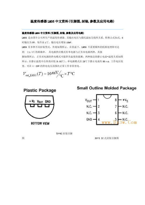
温度传感器LM35中文资料(引脚图,封装,参数及应用电路)温度传感器LM35中文资料(引脚图,封装,参数及应用电路)LM35 是由国半公司所生产的温度传感器,其输出电压与摄氏温标呈线性关系,转换公式如式,0 时输出为0V,每升高1℃,输出电压增加10mV。
LM35 有多种不同封装型式,外观如图所示。
在常温下,LM35 不需要额外的校准处理即可达到±1/4℃的准确率。
其电源供应模式有单电源与正负双电源两种,其接脚如图所示,正负双电源的供电模式可提供负温度的量测;两种接法的静止电流-温度关系如图所示,在静止温度中自热效应低(0.08℃),单电源模式在25℃下静止电流约50μA,工作电压较宽,可在4—20V的供电电压范围内正常工作非常省电。
TO-92封装引脚图SO-8 IC式封装引脚图TO-46金属罐形封装引脚图TO-220 塑料封装引脚图供电电压35V到-0.2V输出电压6V至-1.0V输出电流10mA指定工作温度范围LM35A -55℃ to +150℃LM35C, LM35CA -40℃ to +110℃封装形式与型号关系TO-46金属罐形封装引脚图LM35H,LM35AH,LM35CH,LM35CAH,LM35DHTO-220 塑料封装引脚图LM35DTTO-92封装引脚图LM35CZ,LM35CAZ LM35DZSO-8 IC式封装引脚图LM35DMParameter 参数Conditions条件LM35A LM35CAUnits(Max.)单位Typical典型TestedLimit 测试极限(注4)DesignLimit设计极限(注5)Typical典型TestedLimit测试极限DesignLimit设计极限(注5)介绍一种具有简单人工智能的温度控制电路,使用该电路进行温度控制时,只需将开关打在2的位置,通过设定控制温度,并通过3位半数显表头所显示的温度值,即可精确地控制温度,使得温控操作变得十分方便。
实验十一 LM35温度传感器特性实验

实验十一 LM35温度传感器特性实验【实验目的】1、了解LM35温度传感器的基本原理和温度特性的测量方法;2、测量LM35温度传感器输出电压与温度的特性曲线;【实验仪器】电磁学综合实验平台、LM35温度传感器、加热井、温度传感器特性实验模板【实验原理】1.电压型集成温度传感器(LM35)LM35温度传感器,标准T0-92工业封装,其准确度一般为±0.5℃。
(有几种级别)由于其输出为电压,且线性极好,故只要配上电压源,数字式电压表就可以构成一个精密数字测温系统。
内部的激光校准保证了极高的准确度及一致性,且无须校准。
输出电压的温度系数K V=10.0mV/℃,利用下式可计算出被测温度t(℃):U O=K V*t=(10mV/℃)*t即:t(℃)= U O/10mV (11-1)LM35温度传感器的电路符号见图11-1,V o为输出端实验测量时只要直接测量其输出端电压U o,即可知待测量的温度。
图11-1图11-2LM35传感器特性实验连接图【实验步骤】1、按图11-2,将实验平台加热输出与加热井(加热接口)连接,实验台风扇接口与加热井(风扇接口)连接。
2、调节PID控温表,设置SV:在表面板上按一下(SET)按键,SV表头的温度显示个位将会闪烁;按面板上的“▲”或“▼”键调整设置个位的温度;在按面板上按一下(SET)按键即可,SV表头的温度显示个位将会闪烁,再按“<”键使表头的温度显示十位闪烁,按面板上的“▲”或“▼”键调整设置十位的温度;用同样方法还可设置百位的温度。
调好SV所需设定的温度后,再按一下(SET)按键即可完成设置。
将加热开关选择(快)档加热,待30秒后,仪器开始加热,控温表即可自动控制温度。
调节不同温度,设定参照步骤2进行调节。
3、根据不同的实验连接不同的连接线,可参照上图。
【实验数据】1、LM35传感器(工作电压5V)(直流电压表2V档测量)表11-1t(℃) 30 40 50 60 70 80 90 100U2、描绘.LM35传感器曲线,求出.LM35随温度变化的灵敏度S(mV/℃),【注意事项】1、加热器温度不能加热到120℃以上,否则将可能损坏加热器。
温度传感器LM35中文资料(引脚图,封装,参数及应用电路)

温度传感器LM35中文资料(引脚图,封装,参数及应用电路)
LM35 是由国半公司所生产的温度传感器,其输出电压与摄氏温标呈线性关系,转换公式如式,0 时输出为0V,每升高1℃,输出电压增加10mV。
LM35 有多种不同封装型式,外观如图所示。
在常温下,LM35 不需要额外的校准处理即可达到±1/4℃的准确率。
其电源供应模式有单电源与正负双电源两种,其接
脚如图所示,正负双电源的供电模式可提供负温度的量测;两种接法的静止电流-温度关系如图所示,在静止温度中自热效应低(0.08℃),单电源模式在25℃下静止电流约50μA,工作电压较宽,可在4—20V的供电电压范围内正常工作非常省电。
TO-92封装引脚图 SO-8 IC式封装引脚图
TO-46金属罐形封装引脚图 TO-220 塑料封装引脚图供电电压35V到-0.2V
输出电压6V至-1.0V
输出电流10mA
指定工作温度范围
LM35A -55℃ to +150℃
LM35C, LM35CA -40℃ to +110℃。
LM35数字温度计(最新)

课程设计任务书课程设计内容与要求:以所学EDA课程内容为核心,结合LM35温度传感器,及A/D转换器等内容,设计所需的测温系统。
所设计的温度计的额定温度范围为-55℃—155℃,程序设计部分可利用所学二十四进制计数器进行改编。
对于其他辅助设备,A/D转换器等内容等需查阅资料,对符合要求的型号进行筛选,选出符合条件且最经济适用的部分。
确定其精度大小,适用范围及在整个系统中的连接设置。
将EDA技术应用于芯片设计和系统设计,可极大提高电路设计的效率和可靠性,且节约设计成本。
在实验过程中锻炼了我们的动手能力。
目录1.LM35温度传感器测温系统摘要…………………………2.绪论——整个课程设计的思路……………………………3.Protel99绘图过程…………………………………………4.LM35温度传感器介绍……………………………………5.主要芯片及程序……………………………………………6.技术总结……………………………………………………7.参考文献……………………………………………………8.致谢…………………………………………………………摘要现在EDA技术是电子设计的重要工具,其核心是利用计算机完成电路设计的全程自动化,将EDA技术应用于芯片设计和系统设计,可极大提高电路设计的效率和可靠性,节约设计成本,减少设计人员的劳动强度。
本次课程设计以EDA技术为主体,辅助学习传感器原理,A/D转换器原理,设计LM35温度传感器测温系统,运用LM35为温度传感器收集信号,因为用计算机来构建数据采集系统时看,利用温度传感器的敏感特性,去检测周围的温度,所经采集的温度信号时连续的信号,而计算机能处理不连续变化的信号,因此必须用A/D转换器将模拟信号转换为电信号后进行处理,所以再利用A/D转换器将收集到的模拟信号转换为电信号送入计算机进行处理,再利用显示电路把转换后的数字信号显示出来。
本次设计将介绍EP2C5Q208C8芯片,温度传感器LM35及AD521芯片的基本原理和特点,及利用protel99画图的简要过程。
LM35高精度摄氏温度传感器说明书
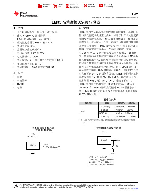
+V SOUTS+V S(4 V to 20 V)ProductFolder OrderNow TechnicalDocuments Tools &SoftwareSupport &CommunityLM35ZHCSHC4H –AUGUST 1999–REVISED DECEMBER 2017LM35高精度摄氏温度传感器1特性•直接以摄氏温度(摄氏度)进行校准•线性+10mV/°C 比例因子•0.5°C 的确保精度(25°C 时)•额定温度范围为−55°C 至150°C •适用于远程应用•晶圆级修整实现低成本•工作电压范围4V 至30V •电流漏极小于60μA•低自发热,处于静止的空气中时为0.08°C •非线性典型值仅±¼°C•低阻抗输出,1mA 负载时为0.1Ω2应用•电源•电池管理•HVAC •电器3说明LM35系列产品是高精度集成电路温度器件,其输出电压与摄氏温度成线性正比关系。
相比于以开尔文温度校准的线性温度传感器,LM35器件的优势在于使用者无需在输出电压中减去一个较大的恒定电压值即可便捷地实现摄氏度调节。
LM35器件无需进行任何外部校准或修整,可在室温下提供±¼°C 的典型精度,而在−55°C 至+150°C 的完整温度范围内提供±¾°C 的精度。
晶圆级的修正和校准可确保更低的成本。
LM35器件具有低输出阻抗、线性输出和高精度内在校准功能,这些特性使得连接读取或控制电路变得尤为简单。
此器件可使用单电源或正负电源供电。
因为LM35器件仅需从电源中消耗60μA 的电流,所以处于静止的空气中时具有不到0.1°C 的极低自发热。
LM35器件额定工作温度范围为−55°C 至150°C ,LM35C 器件额定工作温度范围−40°C 至110°C (−10°时精度更高)。
lm35温度传感器实验原理及知识点
输出特性
输出电压与温度成正比,0℃时输出为0V。适合远程应用,且体积小,功耗低(小于60uA)。
7
应用场景
广泛用于测量特定环境的温度,如电源、电池管理、暖通空调、家电等。也可用作电路/组件的热关断保护。
8
封装类型
提供多种封装型式,如TO-92、TO-220、TO-CAN和SOIC等,以适应不同的应用需求。
12
注意事项
1. 避免在负载为容性的情况下使用,以免产生振荡;2. 在使用单一电源时,无法直接指示低于零度的温度,需要额外配置负电源和下拉电阻。
lm35温度传感器实验原理及知识点
序号
实验原理/知识点
描述/解释
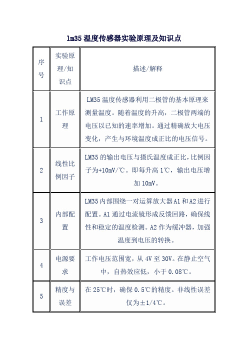
1
工作原理
LM35温度传感器利用二极管的基本原理来测量温度。随着温度的升高,二极管两端的电压以已知的速率增加。通过精确放大电压变化,产生与环境温度成正比的电压信号。
2
线性比例因子
LM35的输出电压与摄氏温度成正比,比例因子为+10mV/℃。即每升高1℃,输出电压增加10mV。
9
测量范围
根据型号不同,测量范围有所不同。如LM35DZ输出为0℃100℃,而LM35CZ输出可覆盖-40℃110℃。
10
实验步骤(示例)
1. 为LM35提供稳定的电源;2. 将LM35的输出连接到ADC或DVM;3. 记录不同温度下的输出电压;4. 根据比例因子计算实际温度。
11
校准与调整
通常情况下,LM35在常温下无需额外校准即可达到较高的准确率。但在特殊应用中,可能需要通过外部电路进行微调。
3
内部配置
LM35内部围绕一对运算放大器A1和A2进行配置。A1通过电流镜形成反馈回路,确保线性和稳定的温度检测。A2作为缓冲器,加强温度到电压的转换。
- 1、下载文档前请自行甄别文档内容的完整性,平台不提供额外的编辑、内容补充、找答案等附加服务。
- 2、"仅部分预览"的文档,不可在线预览部分如存在完整性等问题,可反馈申请退款(可完整预览的文档不适用该条件!)。
- 3、如文档侵犯您的权益,请联系客服反馈,我们会尽快为您处理(人工客服工作时间:9:00-18:30)。
LM35Precision Centigrade Temperature SensorsGeneral DescriptionThe LM35series are precision integrated-circuit temperature sensors,whose output voltage is linearly proportional to the Celsius (Centigrade)temperature.The LM35thus has an advantage over linear temperature sensors calibrated in ˚Kelvin,as the user is not required to subtract a large con-stant voltage from its output to obtain convenient Centigrade scaling.The LM35does not require any external calibration or trimming to provide typical accuracies of ±1⁄4˚C at room temperature and ±3⁄4˚C over a full −55to +150˚C tempera-ture range.Low cost is assured by trimming and calibration at the wafer level.The LM35’s low output impedance,linear output,and precise inherent calibration make interfacing to readout or control circuitry especially easy.It can be used with single power supplies,or with plus and minus supplies.As it draws only 60µA from its supply,it has very low self-heating,less than 0.1˚C in still air.The LM35is rated to operate over a −55˚to +150˚C temperature range,while the LM35C is rated for a −40˚to +110˚C range (−10˚with im-proved accuracy).The LM35series is available packaged inhermetic TO-46transistor packages,while the LM35C,LM35CA,and LM35D are also available in the plastic TO-92transistor package.The LM35D is also available in an 8-lead surface mount small outline package and a plastic TO-220package.Featuresn Calibrated directly in ˚Celsius (Centigrade)n Linear +10.0mV/˚C scale factorn 0.5˚C accuracy guaranteeable (at +25˚C)n Rated for full −55˚to +150˚C range n Suitable for remote applicationsn Low cost due to wafer-level trimming n Operates from 4to 30volts n Less than 60µA current drain n Low self-heating,0.08˚C in still air n Nonlinearity only ±1⁄4˚C typicalnLow impedance output,0.1Ωfor 1mA loadTypical ApplicationsTRI-STATE ®is a registered trademark of National Semiconductor Corporation.DS005516-3FIGURE 1.Basic Centigrade Temperature Sensor(+2˚C to +150˚C)DS005516-4Choose R 1=−V S /50µAV OUT =+1,500mV at +150˚C=+250mV at +25˚C =−550mV at −55˚CFIGURE 2.Full-Range Centigrade Temperature SensorJuly 1999LM35Precision Centigrade Temperature Sensors©1999National Semiconductor Corporation Connection DiagramsTO-46Metal Can Package*DS005516-1*Case is connected to negative pin(GND)Order Number LM35H,LM35AH,LM35CH,LM35CAH orLM35DHSee NS Package Number H03HTO-92Plastic PackageDS005516-2Order Number LM35CZ,LM35CAZ or LM35DZSee NS Package Number Z03ASO-8Small Outline Molded PackageDS005516-21N.C.=No ConnectionTop ViewOrder Number LM35DMSee NS Package Number M08ATO-220Plastic Package*DS005516-24*Tab is connected to the negative pin(GND).Note:The LM35DT pinout is different than the discontinued LM35DP.Order Number LM35DTSee NS Package Number TA03F2Absolute Maximum Ratings(Note10)If Military/Aerospace specified devices are required, please contact the National Semiconductor Sales Office/ Distributors for availability and specifications.Supply Voltage+35V to−0.2V Output Voltage+6V to−1.0V Output Current10mA Storage Temp.;TO-46Package,−60˚C to+180˚C TO-92Package,−60˚C to+150˚C SO-8Package,−65˚C to+150˚C TO-220Package,−65˚C to+150˚C Lead Temp.:TO-46Package,(Soldering,10seconds)300˚CTO-92and TO-220Package,(Soldering,10seconds)260˚C SO Package(Note12)Vapor Phase(60seconds)215˚C Infrared(15seconds)220˚C ESD Susceptibility(Note11)2500V Specified Operating Temperature Range:T MIN to T MAX (Note2)LM35,LM35A−55˚C to+150˚C LM35C,LM35CA−40˚C to+110˚C LM35D0˚C to+100˚CElectrical Characteristics(Notes1,6)LM35A LM35CA Parameter Conditions Tested Design Tested Design UnitsTypical Limit Limit Typical Limit Limit(Max.)(Note4)(Note5)(Note4)(Note5)Accuracy T A=+25˚C±0.2±0.5±0.2±0.5˚C (Note7)T A=−10˚C±0.3±0.3±1.0˚C T A=T MAX±0.4±1.0±0.4±1.0˚CT A=T MIN±0.4±1.0±0.4±1.5˚C Nonlinearity T MIN≤T A≤T MAX±0.18±0.35±0.15±0.3˚C (Note8)Sensor Gain T MIN≤T A≤T MAX+10.0+9.9,+10.0+9.9,mV/˚C (Average Slope)+10.1+10.1Load Regulation T A=+25˚C±0.4±1.0±0.4±1.0mV/mA (Note3)0≤I L≤1mA T MIN≤T A≤T MAX±0.5±3.0±0.5±3.0mV/mA Line Regulation T A=+25˚C±0.01±0.05±0.01±0.05mV/V (Note3)4V≤V S≤30V±0.02±0.1±0.02±0.1mV/V Quiescent Current V S=+5V,+25˚C56675667µA (Note9)V S=+5V10513191114µA V S=+30V,+25˚C56.26856.268µAV S=+30V105.513391.5116µA Change of4V≤V S≤30V,+25˚C0.2 1.00.2 1.0µA Quiescent Current4V≤V S≤30V0.5 2.00.5 2.0µA (Note3)Temperature+0.39+0.5+0.39+0.5µA/˚C Coefficient ofQuiescent CurrentMinimum Temperature In circuit of+1.5+2.0+1.5+2.0˚Cfor Rated Accuracy Figure1,I L=0Long Term Stability T J=T MAX,for±0.08±0.08˚C 1000hours3Electrical Characteristics(Notes1,6)LM35LM35C,LM35D Parameter Conditions Tested Design Tested Design UnitsTypical Limit Limit Typical Limit Limit(Max.)(Note4)(Note5)(Note4)(Note5) Accuracy,T A=+25˚C±0.4±1.0±0.4±1.0˚C LM35,LM35C T A=−10˚C±0.5±0.5±1.5˚C (Note7)T A=T MAX±0.8±1.5±0.8±1.5˚C T A=T MIN±0.8±1.5±0.8±2.0˚CAccuracy,LM35D (Note7)T A=+25˚C±0.6±1.5˚C T A=T MAX±0.9±2.0˚C T A=T MIN±0.9±2.0˚CNonlinearity T MIN≤T A≤T MAX±0.3±0.5±0.2±0.5˚C (Note8)Sensor Gain T MIN≤T A≤T MAX+10.0+9.8,+10.0+9.8,mV/˚C (Average Slope)+10.2+10.2Load Regulation T A=+25˚C±0.4±2.0±0.4±2.0mV/mA (Note3)0≤I L≤1mA T MIN≤T A≤T MAX±0.5±5.0±0.5±5.0mV/mA Line Regulation T A=+25˚C±0.01±0.1±0.01±0.1mV/V (Note3)4V≤V S≤30V±0.02±0.2±0.02±0.2mV/V Quiescent Current V S=+5V,+25˚C56805680µA (Note9)V S=+5V10515891138µA V S=+30V,+25˚C56.28256.282µAV S=+30V105.516191.5141µA Change of4V≤V S≤30V,+25˚C0.2 2.00.2 2.0µA Quiescent Current4V≤V S≤30V0.5 3.00.5 3.0µA (Note3)Temperature+0.39+0.7+0.39+0.7µA/˚C Coefficient ofQuiescent CurrentMinimum Temperature In circuit of+1.5+2.0+1.5+2.0˚C for Rated Accuracy Figure1,I L=0Long Term Stability T J=T MAX,for±0.08±0.08˚C 1000hoursNote1:Unless otherwise noted,these specifications apply:−55˚C≤T J≤+150˚C for the LM35and LM35A;−40˚≤T J≤+110˚C for the LM35C and LM35CA;and 0˚≤T J≤+100˚C for the LM35D.V S=+5Vdc and I LOAD=50µA,in the circuit of Figure2.These specifications also apply from+2˚C to T MAX in the circuit of Figure1.Specifications in boldface apply over the full rated temperature range.Note2:Thermal resistance of the TO-46package is400˚C/W,junction to ambient,and24˚C/W junction to case.Thermal resistance of the TO-92package is 180˚C/W junction to ambient.Thermal resistance of the small outline molded package is220˚C/W junction to ambient.Thermal resistance of the TO-220package is90˚C/W junction to ambient.For additional thermal resistance information see table in the Applications section.Note3:Regulation is measured at constant junction temperature,using pulse testing with a low duty cycle.Changes in output due to heating effects can be com-puted by multiplying the internal dissipation by the thermal resistance.Note4:Tested Limits are guaranteed and100%tested in production.Note5:Design Limits are guaranteed(but not100%production tested)over the indicated temperature and supply voltage ranges.These limits are not used to cal-culate outgoing quality levels.Note6:Specifications in boldface apply over the full rated temperature range.Note7:Accuracy is defined as the error between the output voltage and10mv/˚C times the device’s case temperature,at specified conditions of voltage,current, and temperature(expressed in˚C).Note8:Nonlinearity is defined as the deviation of the output-voltage-versus-temperature curve from the best-fit straight line,over the device’s rated temperature range.Note9:Quiescent current is defined in the circuit of Figure1.Note10:Absolute Maximum Ratings indicate limits beyond which damage to the device may occur.DC and AC electrical specifications do not apply when operating the device beyond its rated operating conditions.See Note1.Note11:Human body model,100pF discharged through a1.5kΩresistor.Note12:See AN-450“Surface Mounting Methods and Their Effect on Product Reliability”or the section titled“Surface Mount”found in a current National Semicon-ductor Linear Data Book for other methods of soldering surface mount devices.4Typical Performance CharacteristicsThermal ResistanceJunction to AirDS005516-25Thermal Time ConstantDS005516-26Thermal Responsein Still AirDS005516-27Thermal Response inStirred Oil BathDS005516-28Minimum SupplyVoltage vs.TemperatureDS005516-29Quiescent Currentvs.Temperature(In Circuit of Figure1.)DS005516-30Quiescent Currentvs.Temperature(In Circuit of Figure2.)DS005516-31Accuracy vs.Temperature(Guaranteed)DS005516-32Accuracy vs.Temperature(Guaranteed)DS005516-33 5Typical Performance Characteristics(Continued)ApplicationsThe LM35can be applied easily in the same way as other integrated-circuit temperature sensors.It can be glued or ce-mented to a surface and its temperature will be within about 0.01˚C of the surface temperature.This presumes that the ambient air temperature is almost the same as the surface temperature;if the air temperature were much higher or lower than the surface temperature,the ac-tual temperature of the LM35die would be at an intermediate temperature between the surface temperature and the air temperature.This is expecially true for the TO-92plastic package,where the copper leads are the principal thermal path to carry heat into the device,so its temperature might be closer to the air temperature than to the surface tempera-ture.To minimize this problem,be sure that the wiring to the LM35,as it leaves the device,is held at the same tempera-ture as the surface of interest.The easiest way to do this is to cover up these wires with a bead of epoxy which will in-sure that the leads and wires are all at the same temperature as the surface,and that the LM35die’s temperature will not be affected by the air temperature.The TO-46metal package can also be soldered to a metal surface or pipe without damage.Of course,in that case the V−terminal of the circuit will be grounded to that metal.Alter-natively,the LM35can be mounted inside a sealed-end metal tube,and can then be dipped into a bath or screwed into a threaded hole in a tank.As with any IC,the LM35and accompanying wiring and circuits must be kept insulated and dry,to avoid leakage and corrosion.This is especially true if the circuit may operate at cold temperatures where conden-sation can occur.Printed-circuit coatings and varnishes such as Humiseal and epoxy paints or dips are often used to in-sure that moisture cannot corrode the LM35or its connec-tions.These devices are sometimes soldered to a small light-weight heat fin,to decrease the thermal time constant and speed up the response in slowly-moving air.On the other hand,a small thermal mass may be added to the sen-sor,to give the steadiest reading despite small deviations in the air temperature.Temperature Rise of LM35Due To Self-heating (Thermal Resistance,θJA )TO-46,TO-46*,TO-92,TO-92**,SO-8SO-8**TO-220no heat sinksmall heat fin no heat sink small heat fin no heat sink small heat fin no heat sink Still air 400˚C/W 100˚C/W 180˚C/W 140˚C/W 220˚C/W 110˚C/W 90˚C/W Moving air 100˚C/W 40˚C/W 90˚C/W 70˚C/W 105˚C/W90˚C/W26˚C/WStill oil 100˚C/W 40˚C/W 90˚C/W 70˚C/W Stirred oil50˚C/W30˚C/W45˚C/W40˚C/W(Clamped to metal,Infinite heat sink)(24˚C/W)(55˚C/W)*Wakefield type 201,or 1"disc of 0.020"sheet brass,soldered to case,or similar.**TO-92and SO-8packages glued and leads soldered to 1"square of 1/16"printed circuit board with 2oz.foil or similar.Noise VoltageDS005516-34Start-Up ResponseDS005516-35 6Typical ApplicationsCAPACITIVELOADSLike most micropower circuits,the LM35has a limited abilityto drive heavy capacitive loads.The LM35by itself is able todrive50pf without special precautions.If heavier loads areanticipated,it is easy to isolate or decouple the load with aresistor;see Figure3.Or you can improve the tolerance ofcapacitance with a series R-C damper from output toground;see Figure4.When the LM35is applied with a200Ωload resistor asshown in Figure5,Figure6or Figure8it is relatively immuneto wiring capacitance because the capacitance forms a by-pass from ground to input,not on the output.However,aswith any linear circuit connected to wires in a hostile environ-ment,its performance can be affected adversely by intenseelectromagnetic sources such as relays,radio transmitters,motors with arcing brushes,SCR transients,etc,as its wiringcan act as a receiving antenna and its internal junctions canact as rectifiers.For best results in such cases,a bypass ca-pacitor from V IN to ground and a series R-C damper such as75Ωin series with0.2or1µF from output to ground are oftenuseful.These are shown in Figure13,Figure14,andFigure16.DS005516-19FIGURE3.LM35with Decoupling from Capacitive LoadDS005516-20FIGURE4.LM35with R-C DamperDS005516-5FIGURE5.Two-Wire Remote Temperature Sensor(Grounded Sensor)DS005516-6FIGURE6.Two-Wire Remote Temperature Sensor(Output Referred to Ground)DS005516-7FIGURE7.Temperature Sensor,Single Supply,−55˚to+150˚CDS005516-8FIGURE8.Two-Wire Remote Temperature Sensor(Output Referred to Ground)DS005516-9FIGURE9.4-To-20mA Current Source(0˚C to+100˚C)7Typical Applications(Continued)DS005516-10FIGURE 10.Fahrenheit ThermometerDS005516-11FIGURE 11.Centigrade Thermometer (Analog Meter)DS005516-12FIGURE 12.Fahrenheit ThermometerExpanded ScaleThermometer(50˚to 80˚Fahrenheit,for Example Shown)DS005516-13FIGURE 13.Temperature To Digital Converter (Serial Output)(+128˚C Full Scale)DS005516-14FIGURE 14.Temperature To Digital Converter (Parallel TRI-STATE ™Outputs forStandard Data Bus to µP Interface)(128˚C Full Scale) 8Typical Applications(Continued)DS005516-16*=1%or2%film resistorTrim R B for V B=3.075VTrim R C for V C=1.955VTrim R A for V A=0.075V+100mV/˚C x T ambientExample,V A=2.275V at22˚CFIGURE15.Bar-Graph Temperature Display(Dot Mode)DS005516-15FIGURE16.LM35With Voltage-To-Frequency Converter And Isolated Output(2˚C to+150˚C;20Hz to1500Hz)9Block DiagramDS005516-23 10Physical Dimensions inches(millimeters)unless otherwise notedTO-46Metal Can Package(H)Order Number LM35H,LM35AH,LM35CH,LM35CAH,or LM35DHNS Package Number H03HSO-8Molded Small Outline Package(M)Order Number LM35DMNS Package Number M08A11Physical Dimensions inches(millimeters)unless otherwise noted(Continued)Power Package TO-220(T)Order Number LM35DTNS Package Number TA03FTO-92Plastic Package(Z)Order Number LM35CZ,LM35CAZ or LM35DZNS Package Number Z03A12Notes LIFE SUPPORT POLICYNATIONAL’S PRODUCTS ARE NOT AUTHORIZED FOR USE AS CRITICAL COMPONENTS IN LIFE SUPPORT DEVICES OR SYSTEMS WITHOUT THE EXPRESS WRITTEN APPROVAL OF THE PRESIDENT AND GENERAL COUNSEL OF NATIONAL SEMICONDUCTOR CORPORATION.As used herein:1.Life support devices or systems are devices orsystems which,(a)are intended for surgical implantinto the body,or (b)support or sustain life,andwhose failure to perform when properly used inaccordance with instructions for use provided in thelabeling,can be reasonably expected to result in asignificant injury to the user.2.A critical component is any component of a life support device or system whose failure to perform can be reasonably expected to cause the failure of the life support device or system,or to affect its safety or effectiveness.National SemiconductorCorporationAmericasTel:1-800-272-9959Fax:1-800-737-7018Email:support@National Semiconductor Europe Fax:+49(0)180-5308586Email:europe.support@ Deutsch Tel:+49(0)180-5308585English Tel:+49(0)180-5327832Français Tel:+49(0)180-5329358Italiano Tel:+49(0)180-5341680National Semiconductor Asia Pacific Customer Response Group Tel:65-2544466Fax:65-2504466Email:sea.support@ National Semiconductor Japan Ltd.Tel:81-3-5639-7560Fax:81-3-5639-7507 LM35PrecisionCentigradeTemperatureSensors National does not assume any responsibility for use of any circuitry described,no circuit patent licenses are implied and National reserves the right at any time without notice to change said circuitry and specifications.。