ICEM六面体网格划分
ICEM-CFD-网格划分-E7-WS6-弯管部件V11
2/2/2005
ANSYS ICEMCFD V11
Inventory #002277 D6-8
ANSYS v11.0
移动顶点
#1 #2
• Blocking > Move Vertex > Set Location
2/2/2005
ANSYS ICEMCFD V11
Workshop
Inventory #002277 D6-17
ANSYS v11.0
察看网格的质量
• Blocking > Pre-Mesh Quality • 设置 Criterion 为 Angle • 指定Histogram Options 如图所示 – Apply • 点击最初的几个条形图来显示成分
ANSYS v11.0
清除 Parts, 创建体, 保存项目
#1 #2
选择 Geometry > Create Body
– 在Part处输入FLUID_MATL
– 单击 MatPt 并且使用 Centroid of 2 points 选项
– 从屏幕上选择2点,如图所示
– 单击右键退出操作
– 在模型树中打开 Geometry > Bodies
Workshop
2/2/2005
ANSYS ICEMCFD V11
Curves and surfaces shown here
Inventory #002277 D6-2
ANSYS v11.0
为曲面建立分组
#2
在模型树中打开 Geometry > Surfaces
ICEM网格拓扑划分
网格划分 for Autodyn
1.简介 2.非结构网格 3.结构网格
本课件为自己学习总结,主要 介绍操作思想。多有步骤随意 命名。希望对大家有帮助!
简介
丰富的几何接口;Solidworks, AutoCAD, ProE, UG……
能输出网格到100多个求解器;
功能强大,能输出结构和非结构网格;
关联,优化网格质量(移动点Blocking- Move Vertex …… 、劈 分线Blocking- Edit Edge ……)。(Determinant>0.2;angle>18 °;Warpage<45°) 8.按要求输出网格(在求解器中进一步的网格操作)。
珍惜劳动成果!切记常存盘!
附录1:ICEM中鼠标的使用
3.导入几何文件(File-Import Geometry)。 (4Bl.o构 ckin思 g-并 Cre建 at B块 loc:k /自 自 Sp下 l上 it B而 而 loc上 下 k): :块 块 的 的 雕 堆 刻 砌
详细步骤
5.关联点和线。 (Blocking-Associate……) 6.设置网格参量(设置网格尺寸或设置Edge的节点数
2D网格6:外O-grid的应用
实体
1、建块: 选中高亮的块,勾选 around block;最后删除中间块 2、关联点线; 3、设置边上节点数
3D网格1
M1 M2
3D网格2 ->自下而上(从小到大)建块
3D网格3 ->简化模型特征,抽象块
分析块->模仿与创新
1
块
网格
2
分析块->弹壳
结构网格的索引与合并->减少总块数,加速求解
ICEM_CFD_关于六面体网格的划分
面的块的定选 ”过穿“ dirg-O –
面加添中程过dirg-O建创在
面加添 – sdirG-O 建创
52
0.5 tnemnorivnE*IA/DFCMECI
8-3-2102
dirg-L 是 向方个一另在 dirg-C是上向方 个一在 来起看
块分划形 角三对来用以可 sdirg-O一之分四
)dirg-L( dirg -O 一之分四
寸尺格网体面六义定速 快寸尺格网线曲和面曲置设过通 – 寸尺格网置设
寸尺格网置设 – 程过块分
31
0.5 tnemnorivnE*IA/DFCMECI 离距元单格网大最上egde– ecapS xaM 离距的点格网个两前侧2 edis – 2 gnicapS 率比长生的心中向2 edis从– 2 oitaR
块择选dirg-O 为
dirG-O 省缺 – sdirG-O建创
42
0.5 tnemnorivnE*IA/DFCMECI
8-3-2102
面这过穿 dirg-O
体何几杂复 –
面平称对 –
端末道管 – 子例用使
)dirg-C( dirg-O 半 面个这过穿 dirg-O
面加添”分部坦平“在 ,下况情般一 –
格 网-O 体 绕
32
0.5 tnemnorivnE*IA/DFCMECI
8-3-2102 xetrev 或 ,egde ,ecaf绕环skcolb 择选
点顶和边部内有所有含块部内 :意注
D3 ni skcolb 7
D2 ni skcolb 5
择选�点角对�dohtem renroc 2 ,�点绕环�xetrev dnuora ,�边绕环�egde dnuora ,�面绕环�ecaf dnuora ,trap ,�部全�lla ,�视可�elbisiv过通以可 –
ICEM网格划分参数总结(仅可参考,不具备一般性)

ICEM网格划分参数总结(仅可参考,不具备一般性)ICEM网格划分参数总结(仅可参考,不具备一般性)一、ICEM CFD网格划分1、模型特征长度1353mm,模型最窄边0.22mm,球体计算域半径28000mm2、各部分参数如下:勾选Prism的Parts就是飞机的机身、圆角、细小的面。
Far的球体,其尺寸等于全局网格尺寸。
Fluid 是body指示网格生成位置。
依照图中所示参数所生成的网格部分信息:T otal elements : 3560021、Total nodes : 12304013、依照上述参数生成网格,在窄边处网格还存在质量较差的部分,数量不是特别巨大,这一部分网格主要集中在机翼、尾翼的后边缘处。
如下图。
二、Fluent求解1、General:Pressure-Based,Absolute Velocity Formulation,Time steady2、Models:开启能量方程、k-e-RNG湍流模型3、Materials:选择理想气体4、边界条件:将球体计算域far设置为压力远场,马赫数0.75,根据需要调整了风速方向(目前仅尝试了alpha=-5~15、beta=-25,21组实验),温度设定223K。
operating condition中operating pressure设定为26412Pa5、参考值:compute from 球体计算域。
参考面积设置为机翼迎风面积0.20762m^2(参考面积这一部分不知道对不对)6、Solution methods:coupled7、Solution controls:库朗数设置为68、初始化:Hybrid Initialization目前对飞机模型进行了修改,根据上述参数重新划分网格,再次调整风速方向进行了2次计算,还能够收敛。
ICEM网格划分原理

基本块
2D:四边形块 3D:六面体块
•
安心+耐心
块 映射 实体
块 Block
点/Vertex 直边/Edge 平面/Face
Point / 点 Curve /曲线 Surface曲面
Patch Independent : 忽略小特征 ShrinkWrap :自动化消除特征 Delanney(beta) : 从表面到内部逐渐粗化 AutoBlock : 2D正交,网格贴近几何表面
• Compute Mesh-Surface Mesh Only(可更改划 分方法),检查网格质量 ; Edit Mesh-Display Mesh Quality
点击apply或ok,然后点击output——〉write/view input,打开uns文 件,output file 给出文件名,点击done。
AUTODYN 中ICEM网格的导入
• 1、新建文件:(File->设置文件名、几何特征、单位) • 2、选择填充材料:Material->Load->选材料 • 3、导入网格:Import->.zon(2D)/.geo,.k(3D)->Import all part • 4、填充材料:Compent->new->起名,选part,点add;
实体:简化
综合运用
旋转;对称;平移
增加插值元素
O grid;C grid; L grid
点:劈分/合并;移动;关联| 增加辅助点
线:劈分;关联
| 增加辅助线
ICEM网格拓扑划分

四种方法划分的网格
All Quad
四边形边界层
All Tri
Quad w/one Tri
Quad Dominant
曲线周围生成四边形层的设置
只适用于几何相关 Pactch dependent 方法
最里一层的 网格高度
从里向外的增长率
层数
非结构体网格
设定线面网格参数值;
定义体区域(Geomerty-Creat Body-Material Point,选体上
结构网格的索引与合并
索引空间
结构网格的索引与合并
详细步骤
1.准备几何模型(.X_T,.dwg等),建立工 作文件夹(路径及文件名全英文)。
2.启动软件,定位工作路径(File-Change Working Directory)。
3.导入几何文件(File-Import Geometry)。 (4Bl.o构ckin思g-并 Cre建at B块lo:ck/自 自Sp下上 lit B而而loc上 下k):: 块 块的 的雕 堆刻 砌
功能强大,能输出结构和非结构网格;
主窗口
修非构 网
改结造 格
几构块 修
何网
补
格
划
分
几何显示 块显示 part显示
非结 结构 构网 网格 格输 输出 出
ANSYS ICEM CFD
非结构网格(Mesh)
划分步骤
设置参数 选择方法 自动划分 大多需修补
认识非结构网格
网格单元 2D:三角形
四边形 3D:四面体
原理示例_曲面
映射
M1 构造块 M2 关联点、线
映射
原理示例_3D
O-grid 建块方法
构造块 点、线的关联
ICEM CFD六面体网格划分

Advanced Engineering Solutions ICEMCFD Hexa Course Sijal AhmedBasic Level Create High Quality Hexa MeshesLecture 3 : Hexa MeshingSee DemoVertexEdgeFaceBlockPointCurveSurfaceVolume•Vertex color coding–Red →Point –Green →Curve –Black →Surface –Cyne →Internal•Edge color coding–Green →Curve –Black →Surface –Cyan →InternalCreate Block•3d bounding box •2d surface blocking •2d planner•3D block from vertices/faces ▪Hexa▪Quarter O-grid▪Degenerate or prism •2D block from verticesDegenerate or prism from 6 verticesQuarter O-grid from 6 verticesHexa from 8 verticesHexa from two facesExtrude Face(s)•Interactive•Select face and MMB whereyou want block•Fixed distance•Specify distance in normaldirection•Along the curve•Select curve and its endwhere you want to end theblockNumber of layers = 530 deg twist2d to 3d blocking •Translation•Rotation✓Choose origin✓Choose axis✓You can also create newparts from points and curvesAssociation•Vertex to point, curve or surface.•Edge to curve or surface.•Face to surface or part.•Edge color coding–Green →Curve –Black →Surface –Cyan →Internal•Vertex color coding–Red →Point –Green →Curve –Black →Surface –Cyne →InternalAll edges are associatedNo AssociationEach edge is associatedto corresponding curveO-GridFull O-GridMesh qualityHow to create O-gridFull O-gridHalf O-gridQuarter O-gridMerge VerticesPropagate MergeSelection of Blocks and Edge for CollapseSide 2 (head of arrow) params17 meshing laws curves/parts to edgesLinked bunchingScale sizes and refinementand refinement.Fraction are allowed whenyou want to coarse themeshfor refinementSelected blockFluent 1:2 RefinementCFX : 1 : 3 RefinementSplit Block •You can use following options:•Screen select•Prescribed point (most commonly used option)•Relative (on scale of 0-1, e.g. 0.5 implies 50% ofedge length)•Absolute (provide distance in units, e.g. in metersof length)•Hidden blocks•Extend split•Split on diagonal edge of O-grid will createanother o-Grid.Without splitMove Vertex•The following options are available for moving vertices:▪Move Vertex▪Set Location ▪Align Vertices ▪Align Vertices In-line ▪Set Edge Length ▪Move Face Vertices •You cannot move red vertex unless its association is changed•Vertex in green color can only slide along curve.•Vertex in black color can only slide over surface, if it is visible.•Vertex in cyne can move along the direction set by edge. •Vertex color coding–Red →Point–Green →Curve–Black →Surface–Cyne →InternalThe following options areavailable for editing block o Unsplit EdgeoLink Edge (link shape of one edge to other edge)o Unlink Edgeo Change Edge Split Type 17Source edge Target edgeMesh quality imporovedEdit Block•Most important options:→Modify O-Grid : Rescale Ogrid & reset Ogrid orthogonality →Modify block →Make periodic (use it with SetupMake periodic option •Use opposite vertices •Any subsequent split operation will make new vertices periodic too. •On axis choose same vertex twicePeriodic vertices▪Translate Blocks▪Rotate Blocks▪Mirror Blocks▪Scale Blocks▪Copy Periodic Blocking ▪Translate and RotateDelete Block•The Delete Block option allows you to delete the blocks from the topologyMonday, April 1, 201920Lecture 4 -Hexa Mesh & BlockingChecking Quality•Using the Quality Histogram–Determinant•Measurement of element deformation (squareness)•Most solvers accept > 0.1•Shoot for > 0.2–Angle•Element minimum internal angles•Shoot for >18 degrees–Aspect ratio–Volume–Warpage•Shoot for < 45 degrees–Many more metricsMonday, April 1, 201921Lecture 4 -Hexa Mesh & Blocking You can display elements in a given range byselecting the histogram barPre-Mesh Smooth & Check Blocks•Following options are available for Pre-Mesh smooth:–Quality –Orthogonality –Multi-block•Following options are available for check blocks:–Run Check/Fix–Fix Inverted Blocks etc。
ICEM网格划分原理ppt课件
三个块
实体
L_grid
29
成块与实体:拓扑分析
基本块
实体
衍生块
30
几何分解_组合块
31
几何分解_组合块
此处复制的每块 的节点都是独立的, 要进行节点的32合并
构思块举例->找到最优块
2D
基
本
O-grid
块
C-grid(二分之一O-grid) L-grid(四分之一O-grrid)
减少 网格 数量
按Material
AUTODYN不支持ICEM的二维网格,可对ICEM输出的网格 文件info.geo编程修改成.zon的格式再导入。
.geo与.zon文件数据段的差别:同样的数据,不同的顺序
53
ICEM二次开发
Solidworks AutoCAD
ProE UG ……
几何实体
ICEM
网格
Autodyn Ls_dyna
5
认识界面
修 非构 非
改 结造 结
几 构块 构
何网
网
格
格
划
修
分
补
几何显示控制 块显示控制 part显示控制
非结 结构 构网 网格 格输 输出 出
几何体视角控制
块的索引控制
6
ANSYS ICEM CFD
非结构网格(Mesh)
划分步骤
设置参数 选择方法 自动划分 大多需网格修补
7
认识非结构网格
网格单元 2D:三角形
42
43
分析块 ->模仿
1
块
网格
2
2D增 块补
44
分析块
45
结构网格的索引与合并->减少总块数,加速求解
- 1、下载文档前请自行甄别文档内容的完整性,平台不提供额外的编辑、内容补充、找答案等附加服务。
- 2、"仅部分预览"的文档,不可在线预览部分如存在完整性等问题,可反馈申请退款(可完整预览的文档不适用该条件!)。
- 3、如文档侵犯您的权益,请联系客服反馈,我们会尽快为您处理(人工客服工作时间:9:00-18:30)。
D1-21
创建O-Grids – 缺省 O-Grid
为 O-grid选择块
– 可以通过visible(可视), all(全部), part, around face (环绕面), around edge(环绕边), around vertex(环 绕点), 2 corner method(对角点)选择
– 如果添加所有环绕块的面, 结果是没有任何变化,因为O-grid 穿 透了所有面
四分之一 Ogrid (L-grid)
看起来 在一个 方向上是C-grid 在另一个方向 是 L-grid
9/9/05
Inventory #002277
D1-24
创建 O-Grids –环绕块
选择 Around block(s) 创建 O-grid 环绕选定的块
9/9/05
Inventory #002277
D1-11
分块过程 – 在几何体上移动块顶 点
移动顶点以更好的表现几何体的形状 – 所有显示的顶点可以立刻投影到 几何体 – 可以单独在几何体上移动它们 – 可以一次移动多个 – 沿着固定平面或线/矢量移动
9/9/05
Inventory #002277
• 根据特定特征对齐网格
– 必须首先 Build Topology – 可在非结构(free)和结构 (mapped)之间转换: Edit Block -> Convert Block Type
非结构块
几何
2D 块
9/9/05
Inventory #002277
D1-9
分块过程 – 构建适合几何体 的块结构 自顶向下方法
分割块 以捕捉几何体形状 从环绕整个几何 体的一个块开始
删除无用的块
注意: 缺省情况 下,删除的块将 放入 part VORFN, 在后面 必要时候可以重 新使用
9/9/05
Inventory #002277
D1-10
分块过程 – 在几何体和块之间建 立关联 关联块到几何体
– 通常在边和曲线建立关联 – 在最后的网格中, 边将投影 到这些曲线 – 在模型树中右击 Edges -> Show association 显示关联 箭头
9/9/05
Inventory #002277
D1-16
观察网格
分块过程 – 观察网格
– 可以在过程任何时期创建网格 – 网格有不同的投影方法 – 选择 Projection faces 可以完全描绘几何体 – 通过在模型树中打开 Part观察指定曲面的网格 – 使用 Scan planes 观察内部网格
5 blocks in 2D
7 blocks in 3D
选择 blocks环绕face, edge, 或 vertex
9/9/05
注意: 内部块含有所有内部边和顶点
Inventory #002277
D1-22
创建 O-Grids – 添加面
在创建O-grid过程中添加面 – O-grid “穿过” 选定的块的面 – 一般情况下,在“平坦部分”添加面 – 增加一个面实际上等价于增加了面两侧的block块
9/9/05
Inventory #002277
D1-13
分块过程 – 设置网格尺寸
设置网格尺寸 – 通过设置曲面和曲线网格尺寸快 速定义六面体网格尺寸
– 或设置edge-by-edge 细化调整
– 自动 copy to parallel edges (复制到平行边)
9/9/05
Inventory #002277
– Aspect ratio 纵横比 – Volume 体积 – Warpage 扭曲
• 争取 < 45 度
通过设置直方图,你可以显示指定质量范围内的网 格单元
9/9/05
Inventory #002277
D1-18
3D Pipe Junction 指南
练习 3D Pipe Junction 实例 #2
• 在z=0的xy平面内环绕2D几何实体创建2D块,即 使几何体不是2D形式 • 并不一定需要2D面
9/9/05
Inventory #002277
D1-8
初始块结构 – 2D 初始化 2D将自动为整个几何体创建面块
– 每一个曲面成为一个2D 块 – Free块对于非结构网格
匠一样逐层创建
– 创建块 – 拉伸面 – 复制拓扑
可以联合使用自顶向下/ 由底向上网格拓扑创建技术
Inventory #002277
9/9/05
D1-3
六面体网格划分的几何要 求
可以使用与划分四面体网格相同的几何模型(tetin) – 不需要几何体结构完全封闭
关联 Face to Surface 到虚的family或插值 Interpolation ,结果 可等价于确实存在几何 体生成的网格
D1-12
颜色表明了关联类型及顶点可以进行的移动方式(边也遵循这一标准, 不包括红色) – 红
Moving Vertices of Different Associations
• 约束到几何点(point)
• 除非改变关联,否则不可移动 – 绿 • 约束到曲线(curve) • 在特定的曲线上滑动 – 白 • 约束到曲面(surfaces) • 在任何 ACTIVE曲面上滑动 (在模型树中打开显示的曲面) • 如果不在曲面上, 将跳到最近的ACTIVE曲面上移动 – 蓝 • 自由(通常是内部)顶点 • 选择顶点附近的边,并在其上移动
块
几何
– 块结构投影到几何体 • 曲面 – 自动的 • 曲线和点 – 手工 – 点,质点,和曲线不是必须的但非常有用 • 使用 Build Topology 快速建立曲线和点
9/9/05
Inventory #002277
D1-4
几何/分块 术语
Geometry 几何 – Point 点 – Curve 曲线
i
9/9/05
Inventory #002277
D1-29
使用索引控制 Blocks can be turned off and on based on indices
– 使用索引控制打开或关闭块显示 – 许多操作可以只针对显示块
Select corners 通常快于复选索引箭 头
• 分割块 • 延伸分割 • 调节 O-grid大小
9/9/05
Inventory #002277
D1-19
O-grid 是一步创建的一系列块结构, 排列成 “O” 型或环绕型
– 3 种基本类型 ,采用相同的操作方法都被称为“O-grids” • O-grid • C-grid (半个 O-grid) • L-grid (四分之一 O-grid) • 圆柱 • 复杂几何 – 提高壁面附近聚集的网格点的效率
9/9/05
Inventory #002277
D1-6
2D Pipe Junction 指南
练习 2D Pipe Junction 实例 #1
9/9/05
Inventory #002277
D1-7
初始分块
创建一个新的块结构, 你必须首先生成一个初始块 – 3D
• 3D 创建的块环绕在几何体周围
– 2D – 2D Planar
网格距离可以链接到其他边
9/9/05
Ratio 2 –从side 2向中心的生长比率 Inventory #002277 Max Space –edge上最大网格单元距离
D1-15
观察边投影形状
网格生成后右击 Edges -> Projected shape 观察边投影形状 – 首先设置网格尺寸, 并计算生成网格, 因为实际上只是将每 条边上的网格点移动到在网格中最后的位置
D1-14
边参数
Spacing 2 = 1.0
Side 2
Ratio 2 = 1.5
Ratio 1 = 1.5
17 划分法 则
箭头指明 side 1 和 side 2
Side 1
Spacing 1 = 1.0
Side 1 箭头底部
要求的 实际
Side 2 箭头顶部
Spacing 1 –side 1侧前两个网格点的距离 Ratio 1 – 从side 1向中心的生长比率 Spacing 2 – side 2侧前两个网格点的距离
O-grid
O- grid – 定义
C-grid L-grid
– 当块必须位于曲线或曲面上时减少歪斜
没有 O-grid
O-grid
9/9/05
Inventory #002277
D1-20
解决环绕固体区域的边界层问题而不必增加网格点数目
绕体O-网格
在对象外围创建O-grid
9/9/05
Inventory #002277
注意: “curve” 指线, 圆弧, 及样条曲线
Blocking
– Vertex 顶点 – Edge 边 – Face 面 – Block 块
Vertex
– Surface 曲面 – Volume 体 (material point, body)
Edge
Curve
Point Surfaces
Face
ICEM六面体网格划分
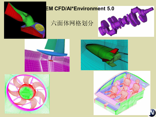
ICEM CFD/AI*Environment V10
六面体网格划分
六面体网格划分步骤 – 自顶 向下/ 由底向上
不依赖几何形状创建块(block)结构 – “自顶向下” 拓扑创建
• 用户将是雕塑家而不是砖瓦匠 • 一步创建高级拓扑结构(O-grid)
O-grid
– “自底向上” 拓扑创建
索引控制
– 初始块包含 i,j,k 索引, 并与全局直角坐标系 x,y,z,对齐