防冻开关安装示意图
邦普SF305000A冷水机控制器
` ELECTRONICSF305000A冷水机控制器厂家使用说明书安装使用控制器之前请详细阅读本说明书!2016/03/16软件功能码:X1.AC003A.F30.001-1 V100A2所有翻印必究!目录一、前言 (1)1.1安全要求 (1)1.2 规格说明 (1)二、安装尺寸图 (2)三、电气连接示意图 (4)四、面板示意图 (5)五、操作说明 (5)5.1 密码输入 (5)5.2 参数初始化 (5)5.3 厂家参数设置 (6)5.4 开关机 (6)5.5 控制温度锁定设置 (6)5.6 控制温度设置 (7)5.7 查看电流 (7)5.8 故障界面 (8)六、参数设置 (8)七、能量调节 (10)八、故障代码 (11)附录 (13)一、前言本控制器具有高抗干扰性、功能全面、性价比高等优点,是同类产品中不可多得的优秀控制器。
1.1安全要求1、请务必详尽阅读“安全要求”,并严加遵守各项安全要求。
2、妥善保管好该使用说明书,以便相关人员随时取阅。
3、指定电源为控制器供电,切勿与其它电器或负载共享同一电源,以免导致负荷过大或电源干扰的危险。
4、务必保证控制器可靠接地并经常检查接地是否牢固。
5、安装、布线时请遵守强弱电分离的原则。
6、稳固安装控制器,以防控制器跌落伤人或损坏。
1.2 规格说明二、安装尺寸图图2.1 主板尺寸图图2.2 KEY板尺寸图`Word文档图2.3 铁面板尺寸图三、电气连接示意图注:图中双压机和单压机是指由厂家参数F-20设定的压机个数。
四、面板示意图显示实时温度显示控制温度故障代码对照表通电后亮非停机状态亮有故障时亮压缩机1运行时亮压缩机2运行时亮复位/消音故障开机增加数值/密码移位使能/禁用压缩机1较少数值使能/禁用压缩机2确认/进入/设定停机五、操作说明5.1 密码输入进入密码输入界面后按照图5.1的提示输入正确密码。
闪烁位代表被选中按切换选中位按修改数值按确认密码图5.1 密码输入方法5.2 参数初始化上电后若出现图5.2-1的界面,表示控制器参数错误。
制冷系统放空气与放油操作+小型冷库热氨霜示意图+制冷剂瓶(回手阀)

制冷系统放空气操作
制冷系统放油操作
小型冷库热氨霜示意图
制冷剂回手阀
制冷剂回手阀是用来回收封闭系统(如电冰箱)内的制冷剂的专用阀。
制冷剂回手阀的外形与专用开瓶阀相似,它由阀体、手抡、V形块、紧固螺母、密封胶圈、阀针等组成。
其结构如(图一)所示。
使用方法:
1、逆时针旋转手轮使阀针退回阀体内,再将紧固螺母旋出并取出V形块。
2、把阀体凹槽卡住制冷系统管路上,将V形块装如并拧紧紧固螺母。
3、顺时针旋转手轮使阀针刺穿制冷系统管路的管壁,然后逆时针旋转手轮使阀针退
回,制冷剂就从排出口排出。
制冷剂瓶
制冷剂瓶是储存制冷剂的专用容器,按充装的制冷剂不同可分为氨瓶和氟利昂瓶等。
按能否重复使用分为一次性制冷剂瓶和重复使用制冷剂瓶。
等组成,容量从10kg至1000kg不等。
氟利昂瓶多为一次性制冷剂瓶,其外形如(图一)所示。
容量有13.6kg、22.7 kg等。
还有一种小容量的氟利昂一次性制冷剂瓶,其外形如(图二)所示。
容量有390g、500g等。
2、因为阀针不能实现良好密封作用,制冷剂开封后应尽快使用,避免泄漏
浪费和污染环境。
暖气片温控阀的一般安装方法介绍ppt课件

散热器温控阀的常规安装位置
温控阀一般是装在散热器前,通过自动调节流 量,实现居民需要的室温,温控阀的感温包与 阀体一般组装成一个整体,感温包本身即是现 场室内温度传感器。如果需要,可以采用远程 温度传感器;远程温度传感器置于要求控温的 房间,阀体置于供暖系统上的某一部位。
7
散热器温控阀的常规安装位置
在每个房间内安装一个温控阀,保障能够充分利用
阳光、照明设施、机械和人体所散发的“免费”热能
,以达到节省能源的效果。
2
OB-30 直接作用式温控阀
适用流体:
最高压力:
阀体最高温度: 温度调节范围: 材料:
毛细管长度: 连接方式: 公称直径:
OB-30,30U 型:加热—蒸汽,温水; 被加热—水,油,液体
OB-31,31U 型:冷却—冷水,制冷剂; 被冷却—水,油,液体
阀体:OB-30,30U 型—1.0MPa {温水—1.7MPa}
OB-31,31U 型—1.7MPa 温包: 1.0MPa 185ºC 0~150ºC 阀体: 青铜; 阀体: 聚四氟乙烯 阀座: 不锈钢; 2m(也生产 3m,5m 的导管) OB-30,31 型: JIS Rc(PT 螺纹) OB-30U,31U 型: JIS Rc(螺纹接头) DN15~DN25
(1)单管顺流户内系统,一个温控阀应该装)带跨越管单管户内系统,一个温控阀应 装户内系统入口供水管或回水管上,该温控阀 远程温度传感器需放户内系统最末端房间里;
8
故障分析
(3)旧建筑上分式单管顺流系统,每根立管一个温 控阀,应装最底层房间散热器上,此时,供热量应采 用热量分配器计量。 应该指出:这种温控阀使用方法, 其优点是既提高了供暖系统调节性能,又能减少工程 初投资;其缺点是每户各房间室温为同一标准,不能 随心所欲进行调节。
邦普SF305000A冷水机控制器

.ELECTRONICSF305000A冷水机控制器厂家使用说明书安装使用控制器之前请详细阅读本说明书!2016/03/16软件功能码:X1.AC003A.F30.001-1 V100A2版权所有翻印必究!目录一、前言 (1)1.1安全要求 (1)1.2 规格说明 (1)二、安装尺寸图 (2)三、电气连接示意图 (4)四、面板示意图 (5)五、操作说明 (5)5.1 密码输入 (5)5.2 参数初始化 (5)5.3 厂家参数设置 (6)5.4 开关机 (6)5.5 控制温度锁定设置 (6)5.6 控制温度设置 (7)5.7 查看电流 (7)5.8 故障界面 (8)六、参数设置 (8)七、能量调节 (10)八、故障代码 (11)附录 (13)一、前言本控制器具有高抗干扰性、功能全面、性价比高等优点,是同类产品中不可多得的优秀控制器。
1.1安全要求1、请务必详尽阅读“安全要求”,并严加遵守各项安全要求。
2、妥善保管好该使用说明书,以便相关人员随时取阅。
3、指定电源为控制器供电,切勿与其它电器或负载共享同一电源,以免导致负荷过大或电源干扰的危险。
4、务必保证控制器可靠接地并经常检查接地是否牢固。
5、安装、布线时请遵守强弱电分离的原则。
6、稳固安装控制器,以防控制器跌落伤人或损坏。
1.2 规格说明二、安装尺寸图图2.1 主板尺寸图图2.2 KEY板尺寸图.图2.3 铁面板尺寸图'.三、电气连接示意图注:图中双压机和单压机是指由厂家参数F-20设定的压机个数。
四、面板示意图显示实时温度显示控制温度故障代码对照表通电后亮非停机状态亮有故障时亮压缩机1运行时亮压缩机2运行时亮复位/消音故障开机增加数值/密码移位使能/禁用压缩机1较少数值使能/禁用压缩机2确认/进入/设定停机五、操作说明5.1 密码输入进入密码输入界面后按照图5.1的提示输入正确密码。
闪烁位代表被选中按切换选中位按修改数值按确认密码图5.1 密码输入方法5.2 参数初始化上电后若出现图5.2-1的界面,表示控制器参数错误。
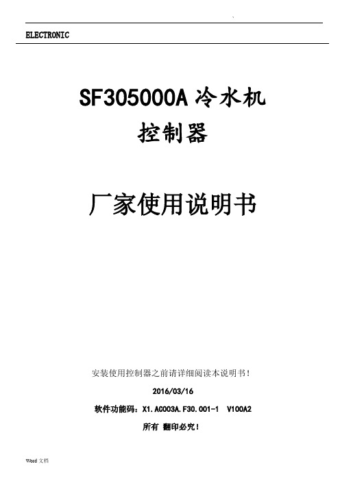
604气体压差开关安装示意及接线图
604气体压差开关安装示意及接线图604系列气体压差开关604系列气体压差开关是用于探测气体压力、压差的设备,如检测过滤网阻塞报警装置,检测空调机组中风机的启/停状态,通风管道中气体监测等。
量程范围:20-300Pa,50-500Pa,100-1000pa,500-200pa,500-2500pa等五种规格可选,详见选型表特点:通过旋钮自由设定,完全满足AHU机组滤网压差报警要求,独特耐高温气膜材料,保证了在微小压差下的灵敏动作,单刀双掷开关,用户可自由选择使用常开或常闭节点,安装简易,顶盖仅需一个固定螺丝,联合支架便于垂直水平安装。
应用:常应用于感知管道中非腐蚀性气体的压力差、真空、过压和气流差等参数,如以下工作状态:·监测过滤网阻塞报警装置·风机运行状态监测·通风管道中气体监测·控制可变气体容积系统中最大气流·燃烧炉中气体控制604气体压差开关安装示意及接线图604气体压差开关选型表:604气体压差安装示意:接线示意图:接线图说明:实际压差小于设定值,触点1-2导通。
实际压差大于设定值,触点1-3导通。
安装位置:安装在振动最小的位置。
媒介温度在-15 / +60范围内。
604的生产校准是在室温下,最好也安装在接近室温环境下。
湿度较高的系统中可能发生水汽凝结现象,应注意软管连接管口向下。
压力连接及接线:压力连接位置标不可接错.注意事项:1. 如果压差开关安装没有按照上述说明,两个端口向下,则开关点检测压差将偏差20Pa,这主要是由压差开关的原理决定(压差开关中有一个非常薄的气膜将内部分为两个腔,如果气膜不是垂直安装而是水平安装,则气膜本身的自重将影响气体压差检测)。
2. 避免电击或损坏设备,移去上盖时应确保电源开关处于关闭状态。
3. 使用前应完成电线连接并检查连接状态。
不正确的连线可能导致此设备永久性损坏。
4. 在低电流(0.1A或更小)情况下,电压小于30V时,建议在电路上连接一个R.C网络。
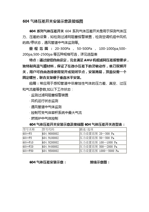
太阳能防冻施工安装指南
防冻施工安装指南本安装指南是指导安装人员如何按照平板太阳能低压封闭系统的设计来安装,保证设计的完整实施,达到预期的效果。
并结合北方工程的要求、特点进行设备、管道的保温,外防护施工和其它防冻措施的实施。
第一章平板太阳能低压封闭系统施工1、系统原理图1、平板集热器;2、进口压力表;3、下循环主管;4、止回阀;5、闸阀;6、板换循环泵;7、闸阀;8、换热器;9、自动排气阀;10、膨胀罐连接管;11、液位传感器;12、上循环主管;13、太阳能循环泵;14、加液泵;15、储液箱;16、压力表及安全阀安装管;17、弹簧式安全阀;18、高压压力表;19、排气管;20、截止阀;21、温度计;22、弹簧式安全阀;23、低压压力表;24、温差控制器;25、膨胀罐;26、温度传感器;2、系统设备、设施安装说明2.1 集热器应采用全铜、铜钎焊流道的集热板芯;串联集热器组的安装坡度宜≥1∶100;各排集热器组的间向安装坡度宜取5∶1000。
2.2 进口压力表选用规格:0~0.3Mpa(且应大于系统安全阀设定的排放压力;置于易观察,不易碰到位置),当系统总面积大于或等于200平方时使用。
2.3 下循环主管低于集热器下集管300mm以上;保温材料采用EPDM橡塑材料,外包0.3mm 厚铝皮。
2.4 板换循环泵采用热水泵,使用温度≥90℃。
2.5 板式换热器采用sus316不锈钢可拆式板式换热器,最大工作压力不小于1.0Mpa,使用温度-50℃~150℃;保温材料采用EPDM橡塑材料,0.8 mm厚镀锌板,板换两端的压板要保温在内。
2.6 自动排气阀装在水侧高位出口管上,如果此管距水箱很近且没有迂回弯可不装。
2.7 膨胀罐连接管膨胀罐(包括储液罐)的连接管不保温;膨胀罐的连接管不小于二米。
2.8 液位传感器系统保护用,低液位传感谢器与集热器下集管平(系统总面积大于或等于200平方时使用)。
2.9 上循环主管低于集热器下集管300mm以上;保温材料采用EPDM橡塑材料,外包0.3mm厚铝皮。
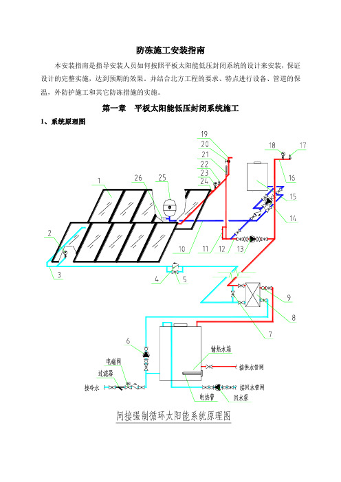
防冻开关TC-5231
Printed in U.S.A. 1/10© Copyright 2010 Schneider Electric All Rights Reserved.F-25911-9ApplicationThe TC-5231, TC-5232, and TC-5241 low temperaturethermostats are used to control temperature in airconditioning or refrigeration systems. The lowtemperature thermostat measures the coldest one-footsection along the entire 20-foot sensing element.The low temperature thermostats are applicable tovarious applications such as: low temperature controlof steam coils; frost indication in storehouses ororchards; temperature control of freezer cabinets,display cases, beverage coolers, milk cooling tanks,and air conditioners.Features•20 ft. (6.1 m) element senses temperature over alarge area. Control responds to coldest one-footsection of the sensor.•Adjustable setpoint from 35 to 60°F (1.7 to 15.5°C)with 5°F (3°C) fixed differential.•SPDT and DPST versions.•Rated for use at 17 full load amps (120/208/240Vac), 24 non-inductive amps (120/208/240 Vac),and 16 non-inductive amps (24 Vac). Capable ofcontrolling refrigeration equipment directly.•UL and CSA approved.•Capillary clips provided.Applicable Literature•Electric/Electronic Products Catalog, F-27382•Environmental Controls Application Manual,F-21335Low Temperature ThermostatsGeneral InstructionsTC-5231 Series, TC-5232,& TC-5241 Series2© Copyright 2010 Schneider Electric All Rights Reserved.F-25911-9SPECIFICATIONSSetpoint Dial Range: Dual marked 35 to 60°F (1.7 to 15.5°C).Sensing Element: Vapor pressure type, copper construction.Response: To lowest temperature sensed by any one-foot section of its element. Altitude causes the control to operate approximately 1°F colder per 1000 ft. of elevation.Differential: 5°F (3°C) fixed.Electrical Switch: Snap action SPDT or DPST. Refer to Table-1.Ratings, Refer to Table-1 and Table-2.Connections:TC-52xx, Screw terminals.Mounting: In any position on any surface not subject to excessive vibration.Housing: Molded gray PVC plastic cover with a zinc-plated steel main enclosure with a 1/2 in. conduit opening.Ambient Temperature Limits:Shipping and Storage, -40 to 150°F (-40 to 66°C).Operating, Must be 5°F (3°C) above setpoint to a maximum of 150°F (66°C) at case. Thermal Sensing Element, 300°F (149°C).Humidity: Enclosure, 5 to 95% RH, non-condensing.Thermal Sensing Element, 0 to 100% RH.Enclosure Rating: NEMA Type 1.Dimensions:Case, 2.7 H x 3.44 W x 1.97 D in. (69 x 87 x 50 mm).Element, 3/32 in. O.D. x 20 ft. length (2.4 mm x 6.1 m).Agency Approvals: UL 873 Temperature-Indicating and -Regulating Equipment and CSA Certified.Table-1Model Chart.Table-2DC Ratings for TC-5232 Only.Model Number Device Type Electrical Switch Voltage Vac Full Load Amps Locked Rotor Amps Pilot Duty (VA)Non-Inductive Amps TC-5231Low temp auto reset SPDT e 24a ——100161201710272024208240c 277———7.2TC-5232Low temp auto reset DPST d 24a ——10016120c 2414412524208c 240c 277———7.2TC-5241Low temp manual reset b SPDT e 24a ——100161201710272024208240c 277———7.2a Less than 0.5 Amp is not recommended.b Reset cannot be accomplished until the sensed temperature is at least 5°F above setpoint.c Full load and locked rotor ratings are suitable for hermetic compressors only.d Limit two separate circuit loads with common return to < 5885 VA. Only one load may be a motor load.e Do not exceed pilot duty rating on one side of switch.Volts FLA LRA NIA PD VA 120 4.646357.5240 2.3230.557.5600———57.5F-25911-9© Copyright 2010 Schneider Electric All Rights Reserved.3INSTALLATIONInspectionInspect the package for damage. If damaged, notify the appropriate carrier immediately.If undamaged, open the package and inspect the device for obvious damage. Returndamaged products.Requirements•Job wiring diagrams•Tools (not provided):–Voltage meter/indicator–Appropriate drill and drill bit for mounting screws–Appropriate screwdrivers and wrenches•Mounting screws, two (2) #10 maximum (not provided)•Capillary mounting clips (5 provided)•Training: Installer must be a qualified, experienced technicianT W A R N I N G•The TC-5231 series, TC-5232, and TC-5241 series devices are designed for use only asoperating controls. Where an operating control failure would result in personal injuryand/or loss of property, it is the responsibility of the installer to add devices (safety, limitcontrols) that protect against, or systems (alarm, supervisory systems) that warn, of con-trol failure.•Disconnect the power supply (line power) before and during installation to prevent possi-ble electrical shock and equipment damage.•Make all connections in accordance with the wiring diagram and in accordance with theNational and Local Electrical Code. Use copper conductors only.•Do not restore electrical power until installation is complete.T C A U T I O N•Do not exceed the electrical ratings indicated on the label inside the cover of the device.•Avoid locations where excessive moisture, corrosive fumes, or vibration are present.Use only in locations suitable for NEMA Type 1 rated devices.MountingT C A U T I O N•Do not kink the capillary or the thermostat will be damaged.•To achieve optimum performance, do not mount the thermal element in a vertical pattern.1.Select a location that permits proper capillary routing. It is important not to twist or strainthe control body or shifting of the calibration may result.N O T E•Use only the mounting holes provided in the control frame. Make sure the mounting surfaceis flat. Mounting the device to an uneven surface may cause improper control operation.•Do not let any part of the capillary touch any surface that is colder than the desiredsensing area.•Do not crush or deform the sensing element when clamping.•Do not cut the capillary or bulb. Avoid sharp bends, kinks, strains, or pinch marks in thecapillary. Never allow the capillary to rest against sharp edges or rub against metalsurfaces.4© Copyright 2010 Schneider Electric All Rights Reserved.F-25911-9F-25911-9© Copyright 2010 Schneider Electric All Rights Reserved.5WiringN O T EDo not adjust the pointer beyond the highest and lowest marks on the scaleplate.The scaleplate is only for reference, and the final settings should be verified with athermometer.T C A U T I O NThe terminals must not be bent, cut off, drilled, or retapped.1.Provide a drip loop in the wiring to prevent water from reaching the thermostat.2.Loosen the green grounding screw provided on the TC-52xx case to connect the unit toearth ground.3.Loosen the terminal screws and make the appropriate power wiring connections to thenumbered terminals. The TC-52xx case has an opening for a 1/2 in. conduit fitting. SeeFigure-1 and Figure-2 for TC-52xx models.4.Replace the cover.5.Adjust the setpoint by turning the setpoint screw until the scale pointer is properlypositioned.6.Check for proper operation of the device. Follow the instructions in the Checkoutsection.7.At initial start-up of the equipment, observe the capillary for excessive vibration andmake corrections as required.6© Copyright 2010 Schneider Electric All Rights Reserved.F-25911-9F-25911-9© Copyright 2010 Schneider Electric All Rights Reserved.7Copyright 2010, Schneider ElectricAll brand names, trademarks and registered trademarks are the property of their respectiveowners. Information contained within thisdocument is subject to change without notice./buildings Schneider Electric 1354 Clifford Avenue P .O. Box 2940Loves Park, IL 61132-2940On October 1st, 2009, TAC became the Buildings business of its parent company Schneider Electric. This document reflects the visual identity of Schneider Electric, however there remains references to TAC as a corporate brand in the body copy. As each document is updated, the body copy will be changed to reflect appropriate corporate brand changes.。
科凌制冷设备操作说明书

目录中文一、操作注意事项(保养及维护) (1)二、安装要求 (1)三、开机准备 (1)四、面板示意图及操作说明 (1)五、修改参数操作说明 (3)六、故障说明 (6)七、故障排除 (6)八、风冷式冷冻机内部结构示图 (8)九、水冷式冷冻机内部结构示意图 (8)十、风冷式冷水机安装示意图............................................. (9)十一、水冷式冷水机安装示意图....................................... . (9)十二、电器连接示意图 (9)感谢您选用科凌冷冻机,为了您能正确高效的使用,请详细阅读说明书。
一、操作注意事项(保养及维护)1、冷冻水泵不可在水箱内无水的情况下运转;(水箱内装有水位保护,当水箱无水或水位太低时,发出水位故障报警信号。
)2、电源操作开关请尽量避免连续切换;如长时间不使用本设备时,请关闭设备总电源。
3、冷冻水温度达到设定温度时,压缩机会自动停止运行,此属正常现象;4、控制温度应避免设定在5℃以下(低温冷冻机除外),防止冷冻介质在蒸发器中结冰损坏机组;长期不使用本机,应把冷冻介质排放干净;5、为确保制冷效果,使整机保持良好运转,请定期清洗冷凝器、蒸发器及水过滤器。
6、风冷式冷冻机散热器表面保持清洁干净,通风良好;水冷式冷冻机冷却水清洁干净,冷却塔内不得有杂物及其它障碍物,定期清洗冷却塔,冷却水温及流量符合使用要求。
7、故障报警时,应及时检查,按第七项和第十项所列方法排除故障,或及时通知维修人员处理。
二、安装要求:1、冷冻机安装前请选择地基平稳,四周空旷,畅通及避免腐蚀、污染、日晒、雨淋,方便安装维修之场所;2、水冷式冷冻机,根据冷冻机制冷量选用匹配的冷却水塔。
冷水机管路配管,请根据机身管路尺寸进行安装,切勿将冷却水管尺寸缩小,这样会引起高压超载,影响制冷效果及增加耗电量;3、风冷式冷冻机,请必须安装在距离墙壁一米以上空间位置,进出风口留出足够的空间,利于通风及设备维护,以免造成散热不良引起高压过载影响制冷效果及增加耗电量。