weeksys温控器说明书
温控器说明书

温控器说明书【篇一:温控器说明书】安全指导在安装、操作和运行本温控器前,请仔细阅读本说明书,并妥善保管。
本温控器有危险电压,并监控电力变压器,如果不按照本说明书的规定操作可能会导致财产损失或人员严重受伤甚至死亡。
只有合格的技术人员才允许操作本温控器,在进行操作之前,要熟悉说明书中所有安全说明、安装、操作和维护规程。
本温控器的正常运行取决于正确的运输、安装、操作和维护。
1、温控器是电子计量产品,其使用寿命为五年,每年需进行周期检验。
2、本温控器只能按照本公司规定的目的和方法使用。
未经授权的修改和使用非本公司所出售或推荐的零配件都有可能导致本系统出现故障,甚至损坏。
3、使用前请您详细阅读该说明书。
设计部门的工作人员请重点参阅性能指标、外形尺寸、机械安装及电气连接;安装人员请重点参阅外形尺寸、机械安装、电气连接及异常现象处理;使用人员请重点参阅基本操作及异常现象处理。
4、每台温控器在使用前应进行功能测试,以保证使用的可靠性及测量、控制的精度。
5、温控器在运输时应采用原包装,以免造成机械损坏。
6、温控器不使用时,请进行防潮处理。
7、温控器使用时应注意电源等级(无特殊说明时,一般为ac220v)。
8、当您准备使用温控器时,请仔细阅读该说明书的电气连接部分,确认连接无误后再给温控器送电!9、为保证温控器输入信号质量,温控器正常运行前务必拧紧传感器插头。
10、在干式变压器进行耐压测试前,必须将传感器插头与温控器分离,以避免温控器被损坏。
11、切勿用打火机等明火对传感器探头进行模拟温升试验,否则会损坏pt100传感器。
12、避免在含有二氧化硫(so2)或其他腐蚀性气体的环境中使用本温控器,否则会使继电器的触点失效。
温控器属于电子精密仪表,请客户妥善保管和放置,如确有问题,本说明书上或温控器面膜上有我公司的服务电话,请客户与本公司联系,公司有专人负责处理,谢谢合作。
同时感谢您使用我公司的温控器产品,不足之处请您提出宝贵意见。
宇电温度控制器使用方法2013-4-7
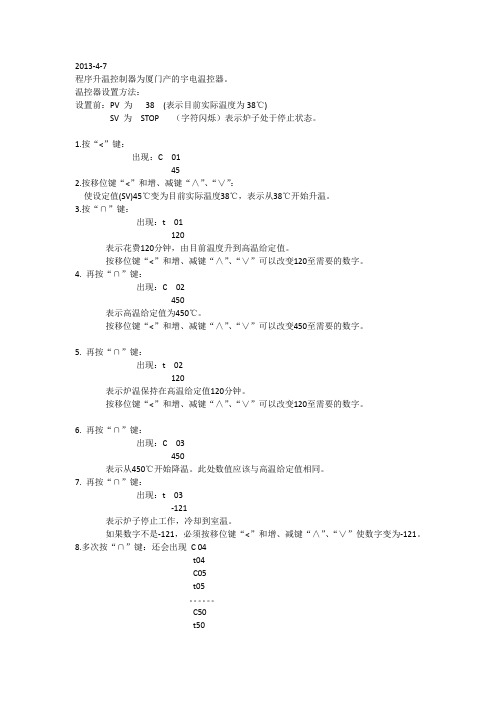
2013-4-7程序升温控制器为厦门产的宇电温控器。
温控器设置方法:设置前:PV 为38 (表示目前实际温度为38℃)SV 为STOP (字符闪烁)表示炉子处于停止状态。
1.按“<”键:出现:C 01452.按移位键“<”和增、减键“∧”、“∨”:使设定值(SV)45℃变为目前实际温度38℃,表示从38℃开始升温。
3.按“∩”键:出现:t 01120表示花费120分钟,由目前温度升到高温给定值。
按移位键“<”和增、减键“∧”、“∨”可以改变120至需要的数字。
4. 再按“∩”键:出现:C 02450表示高温给定值为450℃。
按移位键“<”和增、减键“∧”、“∨”可以改变450至需要的数字。
5. 再按“∩”键:出现:t 02120表示炉温保持在高温给定值120分钟。
按移位键“<”和增、减键“∧”、“∨”可以改变120至需要的数字。
6. 再按“∩”键:出现:C 03450表示从450℃开始降温。
此处数值应该与高温给定值相同。
7. 再按“∩”键:出现:t 03-121表示炉子停止工作,冷却到室温。
如果数字不是-121,必须按移位键“<”和增、减键“∧”、“∨”使数字变为-121。
8.多次按“∩”键:还会出现C 04t04C05t05。
C50t50这些程序设定不影响前面的程序升、降温。
只要t 03设为-121,就表示停炉,不再执行C04—t50的程序设定。
9.长按“∨”键:(RUN)等待STOP(字符闪烁)出现,长按“∨”键,出现“run”字符,表示炉子开始工作,开始程序升温。
长按“∧”键:(STOP)表示炉子立即停止工作,进入STOP状态。
温控器说明书
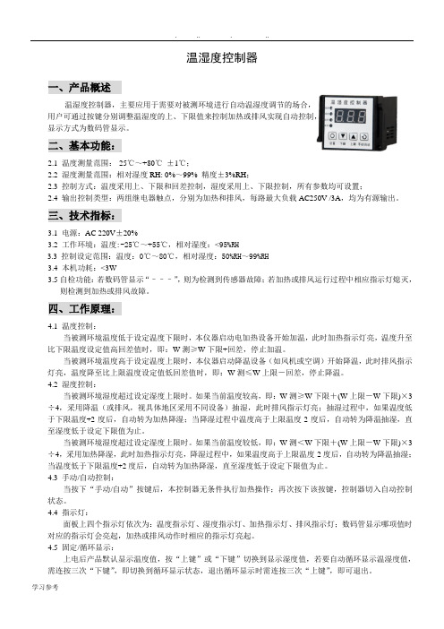
温湿度控制器一、产品概述温湿度控制器,主要应用于需要对被测环境进行自动温湿度调节的场合,用户可通过按键分别调整温湿度的上、下限值来控制加热或排风实现自动控制,显示方式为数码管显示。
二、基本功能:2.1 温度测量范围:-25℃~+80℃±1℃;2.2 湿度测量范围:相对湿度RH: 0%~99% 精度±3%RH;2.3 控制方式:温度采用上、下限和回差控制,湿度采用上、下限控制,所有参数均可设置;2.4 输出控制类型:两组继电器触点,分别为加热和排风,每路最大负载AC250V /3A,均为有源输出。
三、技术指标:3.1电源:AC 220V±20%3.2 工作环境:温度:-25℃~+55℃,相对湿度:<95%RH3.3控制设定范围:温度:0℃~80℃,相对湿度:50%RH~99%RH3.4 本机功耗:<3W3.5自检功能:若数码管显示“–––”,则为检测到传感器故障;若加热或排风运行过程中相应指示灯熄灭,则检测到加热或排风故障。
四、工作原理:4.1 温度控制:当被测环境温度低于设定温度下限时,本仪器启动电加热设备开始加温,此时加热指示灯亮,温度升至比下限温度设定值高回差值时,即:W测≥W下限+回差,停止加温。
当被测环境温度高于设定温度上限时,本仪器启动降温设备(如风机或空调)开始降温,此时排风指示灯亮,温度降至比上限温度设定值低回差值时,即:W测≤W上限-回差,停止降温。
4.2 湿度控制:当被测环境湿度超过设定湿度上限时。
如果当前温度较高,即:W测≥W下限+(W上限-W下限)×3÷4,采用降温(或排风,视具体地区采用不同设备)抽湿,此时排风指示灯亮;抽湿过程中,如果温度低于下限温度+2度后,自动转为加热降湿;当降湿过程中温度高于上限温度-2度后,自动转为降温抽湿,直至湿度低于设定下限值为止。
当被测环境湿度超过设定湿度上限时。
如果当前温度较低,即:W测<W下限+(W上限-W下限)×3÷4,采用加热降湿,此时加热指示灯亮,降湿过程中,如果温度高于上限温度-2度后,自动转为降温抽湿;当温度低于下限温度+2度后,自动转为加热降湿,直至湿度低于设定下限值为止。
温控器说明书

说明书设计题目温控器设计姓名:张龙学号:2011071128专业:机械工程及自动化目录摘要 (3)1 设计内容与设计要求 (4)2、方案选择 (4)2.1 单片机的选择方案 (4)2.2显示器的选择方案 (4)2.3 模数转换芯片的选择 (5)3、元器件介绍 (5)3.1 AT89C51 (5)3.2 LCD1602液晶屏 (6)3.3 ADC0804 (8)3.4 NPN型三极管 (9)4.系统硬件设计 (10)4.1时钟电路 (11)4.2 复位电路 (12)4.3 ADC转换电路 (14)4.4 LCD1602液晶显示器 (14)4.5 独立按键控制电路 (15)4.6 继电器控制电路 (15)5.软件设计 (16)总结 (17)摘要温控器(Thermostat),根据工作环境的温度变化,在开关内部发生物理形变,从而产生某些特殊效应,产生导通或者断开动作的一系列自动控制元件,也叫温控开关、温度保护器、温度控制器,简称温控器。
或是通过温度保护器将温度传到温度控制器,温度控制器发出开关命令,从而控制设备的运行以达到理想的温度及节能效果,其应用范围非常广泛,根据不同种类的温控器应用在家电、电机、制冷或制热等众多产品中。
其工作原理是通过温度传感器对环境温度自动进行采样、即时监控,当环境温度高于控制设定上限值时控制电路启动,温度下降。
当环境温度低于控制设定下限值时,控制电路不工作,温度上升。
主要应用于电力部门使用的各种高低压开关柜、干式变压器、箱式变电站及其他相关的温度使用领域。
关键词:温控器温度采样上限值下限值1 设计内容与设计要求基本内容:设计一个简易温控器基本要求:①可以设定上限温度和下限温度,温度高于上限温度上,主电路不工作,温度降低,温度低于下限控制电路时,主电路继续工作,温度升高。
③设定温度时,液晶屏上显示设定状态,设定完显示正常模式,并且设定的上下限温度,在液晶屏上都有显示。
⑤采集温度信号,转换成数字信号。
欧姆龙温控器说明
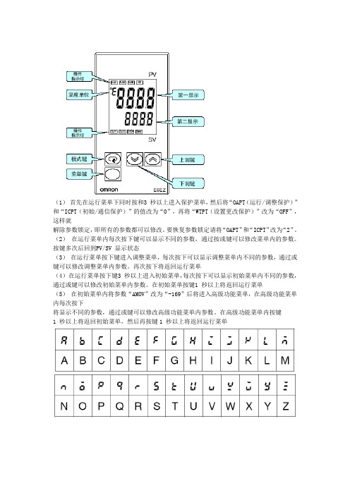
(1)首先在运行菜单下同时按和3 秒以上进入保护菜单,然后将“OAPT(运行/调整保护)”和“ICPT(初始/通信保护)”的值改为“0”,再将“WTPT(设置更改保护)”改为“OFF”,这样就
解除参数锁定,即所有的参数都可以修改。
要恢复参数锁定请将“OAPT”和“ICPT”改为“2”。
(2)在运行菜单内每次按下键可以显示不同的参数,通过按或键可以修改菜单内的参数。
按键多次后回到PV/SV 显示状态
(3)在运行菜单按下键进入调整菜单,每次按下可以显示调整菜单内不同的参数,通过或键可以修改调整菜单内参数。
再次按下将返回运行菜单
(4)在运行菜单按下键3 秒以上进入初始菜单,每次按下可以显示初始菜单内不同的参数,通过或键可以修改初始菜单内参数。
在初始菜单按键1 秒以上将返回运行菜单
(5)在初始菜单内将参数“AMOV”改为“-169”后将进入高级功能菜单,在高级功能菜单内每次按下
将显示不同的参数,通过或键可以修改高级功能菜单内参数。
在高级功能菜单内按键
1 秒以上将返回初始菜单,然后再按键1 秒以上将返回运行菜单。
恒温控制器用户操作指南说明书
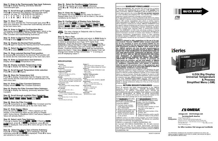
Step 11. Enter to the Thermocouple Type Input Submenu Press d to display flashing, previously selected Thermocouple type.Step 12. Scroll through available selection of TC types Press b to sequence thru flashing Thermocouple types,(select k -for type "K" CHROMEGA ®/ALOMEGA ®)J K T E N DIN J R S B C - TC types J k t E N dN J R S b C - DisplayStep 13. Store TC typeAfter you have selected the Thermocouple type press d to store your selection, the instrument automatically advances to the next menu item.Step 14. Enter to Reading Configuration MenuThe display shows RDG Reading Configuration, which is the top menu for 4 submenus: Decimal Point, Degree Units,Filter Constant and Input/Reading Submenus.Step 15. Enter to Decimal Point Submenu Press d to show DEC Decimal Point.Step 16. Display the Decimal Point positionPress d again to display the flashing Decimal Point position.Step 17. Select the Decimal Point position Press b to select FFF.F Decimal Point position.Step 18. Store selected Decimal Point positionBy pressing d momentarily the Decimal Point position will be stored and the instrument will go to the next menu item.Step 19. Enter to Temperature Unit Submenu Display shows TEMP Temperature Unit.Step 20. Display available Temperature Units Press d to display the flashing Degree °F or °C .Step 21. Scroll through Temperature Units selection Press b to select °F Degree.Step 22. Store the Temperature UnitPress d to display momentarily that the Degree Unit has been stored and the instrument will go automatically to the next menu item.Step 23. Enter the Filter Constant Submenu Display shows FLTR Filter Constant Submenu.Step 24. Display the Filter Constant Value Submenu Press d to display the flashing, previously selected Filter Constant.Step 25. Scroll through available Filter Constants Press b to sequence thru Filter Constants 0001, 0002,0004, 0008, 0016, 0032, 0064and 0128.Step 26. Store the Filter ConstantPress d momentarily to store 0004Filter Constant and the instrument will automatically go to the next menu item.Step 27. Enter Alarm 1 MenuPress a until the ALR1Alarm 1 Menu appears on the Display. In the following steps we are going to DisableLatch, Active Above, Deadband 020.0, and above Setpoint 1Value will activate Alarm 1.Step 28. Select Latch Type SubmenuPress d to display flashing DSBL / ENBL .If flashing DSBL is displayed, press a , if ENBL is displayed, press buntil DSBL is displayed, then press d to store and go to the next menu item.Step 29. Select the Above Type of Active Submenu Press d . If flashing ABoV Above is displayed, press a ,otherwise press b until ABoV is displayed. Press d to store and advance to next menu item.MQS3716-SM/0305iLD24 Big Display Universal Temperature&ProcessSimplified Menu (-SM)WARRANTY/DISCLAIMEROMEGA ENGINEERING, INC. warrants this unit to be free of defects in materials and workmanship for a period of 61 months from date of purchase. OMEGA’s WARRANTY adds an additional one (1) month grace period to the normal five (5) year product warranty to cover handling and shipping time. T his ensures that OMEGA’s customers receive maximum coverage on each product.If the unit malfunctions, it must be returned to the factory for evalua-tion. OMEGA’s Customer Service Department will issue an Authorized Return (AR) number immediately upon phone or written request. Upon examination by OMEGA, if the unit is found to be defective, it will be repaired or replaced at no charge. OMEGA’s WARRANTY does not apply to defects resulting from any action of the purchaser, includ-ing but not limited to mishandling, improper interfacing, operation outside of design limits, improper repair, or unauthorized modifica-tion. This WARRANTY is VOID if the unit shows evidence of having been tampered with or shows evidence of having been damaged as a result of excessive corrosion; or current, heat, moisture or vibration; improper specification; misapplication; misuse or other operating conditions outside of OMEGA’s control. Components in which wear is not warranted, include but are not limited to contact points, fuses, and triacs.OMEGA is pleased to offer suggestions on the use of its vari-ous products. However, OMEGA neither assumes responsibil-ity for any omissions or errors nor assumes liability for any damages that result from the use if its products in accordance with information provided by OMEGA, either verbal or writ-ten. OMEGA warrants only that the parts manufactured by the company will be as specified and free of defects. OMEGA MAKES NO OTHER WARRANTIES OR REPRESENTATIONS OF ANY KIND WHATSOEVER, EXPRESSED OR IMPLIED, EXCEPT THAT OF TITLE, AND ALL IMPLIED WARRANTIES INCLUDING ANY W ARRANTY OF MERCHANTABILITY AND FITNESS FOR A PARTICULAR PURPOSE ARE HEREBY DISCLAIMED. LIMITATION OF LIABILITY: The remedies of purchaser set forth herein are exclusive, and the total liability of OMEGA with respect to this order, whether based on contract, warran-ty, negligence, indemnification, strict liability or otherwise, shall not exceed the purchase price of the component upon which liability is based. In no event shall OMEGA be liable for consequential, incidental or special damages.CONDITIONS: Equipment sold by OMEGA is not intended to be used, nor shall it be used: (1) as a “Basic Component” under 10 CFR 21 (NRC), used in or with any nuclear installation or activity; or (2) in medical appli-cations or used on humans. Should any Product(s) be used in or with any nuclear installation or activity, medical application, used on humans, or misused in any way, OMEGA assumes no responsibility as set forth in our basic WARRANT Y/DISCLAIMER language, and, additionally, purchaser will indemnify OMEGA and hold OMEGA harmless from any liability or damage whatsoever arising out of the use of the Product(s) in such a manner.RETURN REQUESTS/INQUIRIESDirect all warranty and repair requests/inquiries to the OMEGA Customer Service Department. BEFORE RE URNING ANY PRODUC (S) O OMEGA, PURCHASER MUS OB AIN AN AUTHORIZED RETURN (AR) NUMBER FROM OMEGA’S CUSTOMER SERVICE DEPART MENT (IN ORDER T O AVOID PROCESSING DELAYS). T he assigned AR number should then be marked on the outside of the return package and on any correspondence.FOR WARRANTY RETURNS, please have the followinginformation available BEFORE contacting OMEGA:1. Purchase Order number under which the product was PURCHASED,2.3. Model and serial number of the product under warranty, and Repair instructions and/or specific problems relative to the product.FOR NON-WARRANTY REPAIRS, consult OMEGA for current repair charges. Have the following information available BEFORE contacting OMEGA:1. P urchase Order number to cover the COST of the repair or calibration,2.3.Model and serial number of the product, and R epair instructions and/or specific problems relative to the product.OMEGA’s policy is to make running changes, not model changes, whenever an improvement is possible. This affords our customers the latest in technology and engineering.OMEGA is a trademark of OMEGA ENGINEERING, INC.© Copyright 2018 OMEGA ENGINEERING, INC. All rights reserved. T his document may not be copied, photocopied, reproduced, translated, or reduced to any electronic medium or machine-readable form, in whole or in part, without the prior written consent of OMEGA ENGINEERING, INC.***********************Servicing North America:Omega Engineering, Inc.Toll-Free: 1-800-826-6342 (USA & Canada only)Customer Service: 1-800-622-2378 (USA & Canada only) Engineering Service: 1-800-872-9436 (USA & Canada only) Tel: (203) 359-1660 Fax: (203) 359-7700 e-mail:**************For Other Locations Visit /worldwidehis Quick Start Reference provides information on setting up your instrument for basic operation. The latest complete Communication and Operational Manual as well as free Software and ActiveX Controls are available at or on the CD-ROM enclosed with your shipment .SAFETY CONSIDERATIONThe instrument is a panel mount device protected in accordance with EN 61010-1:2001, electrical safetyrequirements for electrical equipment for measurement, control and laboratory.Remember that the unit has no power-on switch. Building installation should include a switch or circuit-breaker that must be compliant to IEC 947-1 and 947-3.SAFETY:•Do not exceed voltage rating on the label located on the back of the instrument housing.•Always disconnect power before changing signal and power connections.•Do not use this instrument on a work bench without its case for safety reasons.•Do not operate this instrument in flammable or explosive atmospheres.EMC:•Whenever EMC is an issue, always use shielded cables. •Never run signal and power wires in the same conduit.•Use signal wire connections with twisted-pair cables.•Install Ferrite Bead(s) on signal wire close to the instrument if EMC problems persist.。
智能温控器操作手册
智能温控器操作手册关键信息项:1、温控器型号:____________________________2、适用环境:____________________________3、电源要求:____________________________4、温度测量范围:____________________________5、温度控制精度:____________________________6、操作方式:____________________________7、显示界面:____________________________8、安全保护功能:____________________________11 产品概述本智能温控器是一款用于精确控制环境温度的设备,具有先进的温度感知和调节功能,能够为您提供舒适、节能的温度控制解决方案。
111 工作原理智能温控器通过内置的温度传感器实时监测环境温度,并将测量值与用户设定的温度目标值进行比较。
根据比较结果,温控器自动控制加热或制冷设备的运行,以维持设定的温度范围。
112 主要特点高精度温度控制,提供稳定舒适的环境温度。
简洁直观的操作界面,方便用户设置和操作。
节能模式,有效降低能源消耗。
多种安全保护机制,确保使用安全可靠。
12 安装与连接121 安装位置选择选择安装在能够准确反映环境温度的位置,避免阳光直射、靠近热源或冷源以及通风不良的区域。
122 电源连接按照温控器的电源要求,正确连接电源。
确保电源稳定,以保证温控器正常工作。
123 与加热/制冷设备的连接根据设备的类型和接口要求,正确连接温控器与加热或制冷设备的控制线。
13 操作界面与显示131 显示屏温控器配备清晰的液晶显示屏,用于显示当前温度、设定温度、工作模式等信息。
132 按键功能包括设置键、上调键、下调键、模式切换键等,通过这些按键可进行各种参数的设置和操作。
14 温度设置141 设定温度范围明确可设定的温度上下限。
温控器说明书 (2)10页word
通过ISO9002国际质量体系认证conformity Certification of ISO9002 Quality Management SystemBWY(WTYK)-802、803系列变压器温度控制器SERIES TRANSFORMER TEMPERATURE CONTROLLER使用说明书DESCRIPTION & OPERATION INSTRUCTIONS杭州华立仪表有限公司HANG ZHOU HUALI INSTRUMENT & METER GENERAL PLANT感谢您使用本厂产品使用前请认真阅读产品使用说明书THANKS FOR USING OUR PRODUCTSPLEASE READ THE DIRECTIONS BEFORE USE目录一、概况 (1)二、工作原理 (5)三、主要技术指标 (5)四、安装及使用 (5)五、注意事项 (10)六、附录Pt100工业铂电阻分度值表 (11)第 2 页一、概况1、温度控制器根据沈阳变压器研究所制订的JB/T6302-92《变压器用压力式温度计》标准的命名如下:2、温度控制器根据JB/T9236-2019《工业自动化仪表产品型号编制原则》的要求产品命名如下:第 3 页第 4 页二、工作原理变压器温度控制器(以下简称温控器),主要由弹性元件、毛细管、温包和微动开关组成。
当温包受热时,温包内感温介质受热膨胀所产生的体积增量,通过毛细管传递到弹性元件上,使弹性元件产生一个位移,这个位移经机构放大后指示出被测温度并带动微动开关工作,从而控制冷却系统的投入或退出。
BWY(WTYK)-802A、803A温控器采用复合传感器技术,即仪表温包推动弹性元件的同时,能同步输出Pt100热电阻信号,此信号可远传到数百米以外的控制室,通过XMT数显温控仪同步显示并控制变压器油温。
也可通过数显仪表,将Pt100热电阻信号转换成与计算机联网的直流标准信号(0~5V、1~5V或4~20mA)输出。