Norval调压器说明书
单杆 单位位置或三路(多位置)旋转调节器120VAC, 60Hz说明书

fuse. Installation is complete.
Connect wires per WIRING DIAGRAM as follows: Screw wire nuts on clockwise making sure no bare conductors show below the wire connectors. Secure each connector with electrical tape. NOTE: Control can be installed on either the Load or Line side. • Green dimmer Ground lead to Green or bare copper
wires.
• Remaining Red dimmer lead to remaining wall box wire.
• Proceed to Step 6.
Step 5b 3-Way Wiring Application:
Black Red Green Red
Neutral Ground
Insert wires straight then
twist clockwise
Electrical Tape
Step 7 Dimmer Mounting:
leads.
• Make sure that the ends of the wires from
the wall box are straight (cut if
necessary).
• Remove 5/8" (1.6 cm) of insulation from
RS60N Series 旋转潜入式调节器说明书

103
10
503
50
Code 104 254
G 100 (%) J
Output volt.across term.1-2 Input volt. across term. 1-3
100 90 80
70
60
50
40
30
B(1B)
20
A(15A)
10
D(10A)
0 10 20 30 40 50 60 70 80 90 100
0.5mm max.ʢOne sideʣ
sखMol adneΜurianͩlg
σsΟolοdDϓeiprinΜgͩ
-
350ˆ max. 3s max.
260ˆ max. 5s max. RS˘˘N1˘.ʢLead typeʣ, RSA0K1˘Vɿnot available
Cold
ʵ30ʶ2ˆ for 96h
5.63
11.25
128 120
2-M3
4
100
0.5
t=1.2
16
18.5
14.5
8
1.5
18.5
1.5
4 8.2
8 8.2
3.5
3.3
1 1.5
21 1' 2'
6-ø1.5 holes
127.5
82.5
43.7
38.8
3
3'
2-ø2 holes
3.75
431
Low-profile Master Type Slide Potentiometeʢr N Faderʣ
Term."1"
Rotation travel (%) J Term."3"
三相交流调压器说明书

KTF40A380V 三相交流调压器使用说明书单位:西安协科电子有限责任公司地址:西安市雁塔区朱雀大街88号邮编:7100612011年5月1日目录装置说明1,本装置型号意义--------------------------------------------------------1 2,技术规范-----------------------------------------------------------------1 3,工作原理-----------------------------------------------------------------2 4,装置电路图-------------------------------------------------------------4 5,控制板接口图----------------------------------------------------------5 6,装置元件布局----------------------------------------------------------6 控制板说明书--------------------------------------------------------------7一、概述----------------------------------------------------------------------7二、触发电路组成------------------------------------------------------------8三、适用装置-----------------------------------------------------------------8四、正常使用条---------------------------------------------------------------8五、主要技术参数------------------------------------------------------------8六、控制板的接线端子与参数-----------------------------------------------8七、发光二极管工作状态---------------------------------------------------10八、电位器-------------------------------------------------------------------10九、 同步输入---------------------------------------------------------------11十、 调试须知---------------------------------------------------------------11十一、控制板应用举例------------------------------------------------------11 XK104B、C在三相桥式整流电路中的应用-------------------------12XK104D在三相桥式整流电路中的应用-----------------------------13XK104B、C在三相相控调压电路中的应用-------------------------14XK104D在三相相控调压电路中的应用-----------------------------15附录A:PCB板------------------------------------------------------------16附录B:控制板接线图--------------------------------------------------17附录C:原理图-----------------------------------------------------------18模块资料-------------------------------------------------------------------19 XKMTC70AT120/180----------------------------------------------------------191,本装置型号意义:K T F-40A/380V3PH50HZ可控硅变流装置3相50Hz调压额定整流电压(V)风冷额定整流电流(A)2 技术规范:2.1 主要技术参数:a.额定输出电流: 40Ab.额定输出电压: 380Vc.负载等级: Ⅱ级 100% Idn 连续, 150%Idn 1分钟;d.冷却方式: 风冷e.主柜外形尺寸: 350×240 (长×宽)2.2 正常使用条件:本装置除了应满足GB3895-83《半导体电力变流器》、ZBK46-006-88《电化学整流器标准》外, 还应满足本产品的技术要求:a.环境温度: 户内不低于-5℃,不高于+40℃,24小时内的平均温度不超过30℃b. 空气最大相对湿度不超过90%c. 运行地点无导电及爆炸性尘埃,无腐蚀金属和破坏绝缘的气体或蒸汽。
调压器说明书
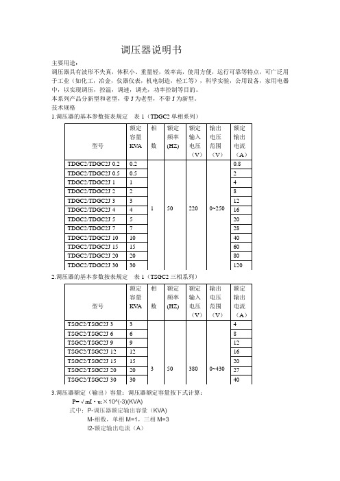
调压器说明书主要用途:调压器具有波形不失真,体积小、重量轻,效率高,使用方便,运行可靠等特点,可广泛用于工业(如化工,冶金,仪器仪表,机电制造,轻工等),科学实验,公用设备,家用电器中,以实现调压,控温,调速,调光,功率控制等目的。
本系列产品分新型和老型,带J为老型,不带J为新型。
技术规格1.调压器的基本参数按表规定表1(TDGC2单相系列)2.调压器的基本参数按表规定表1(TSGC2三相系列)3.调压器额定(输出)容量:调压器额定容量按下式计算:P=√mI·u2×10^(-3)(KVA)式中:P-调压器额定输出容量(KVA)M-相数,单相M=1,三相M=3I2-额定输出电流(A)U2-最大输出电流(V)(三相为线电压)过载(%)不超过(分钟)20 6040 3060 64、调压器绝缘等级为A级,线圈平均温升限值为60℃5、过负荷能力,调压器允许短时间超过额定输出电流值。
但不能超过表2的规定基本原理与主要结构1.基本原理:调压器电刷借助于手轮主轴和刷架的作用,言线圈的磨光表面滑动,变化电刷接触位置、改变一次和二次线圈匝数比,以达到调压的目的。
2、主要结构:①单位结构:单相0.2KV A~10KV A调压器为调压单元结构,一个上端面具有一定宽度的磨光表面的线圈固定在工程塑料的底座上,接触组的电刷在弹簧压力下与线圈的磨光表面金梅接触,转动手轮带动电刷在线圈磨光表面上滑动进行调压。
单元调压器一般为台式,外面有防护通风罩。
单元调压器绕组联接如图一所示:注:图中U1-输入电压(伏)U2-输出电压(伏)D-电刷②单相组装结构,单相大容量调压器是由几个相同规格的单元组装而成,各单元的电刷接触组装在同一主轴上,线圈输入端并联连接平衡电抗器,以平衡单元间电流分布并抑制环流。
单相大容量调压器绕组联接如图2.图3所示:U1-输入电压U2-输出电压D-电刷DK DK1 DK2是平衡电抗器③三相组装结构:三相调压器由三个相同规格的单元同轴组装而成。
RECOM 电源调压器 R-5xxxA 系列数据手册说明书

FeaturesSwitching Regulator• Non-isolated• Synchronous rectification design • Adjustable output voltage• 2, 3, 4 & 5AMP adjustable positive step down integrated switching regulator • Over load protection• Continuous short circuit protection • Efficiency up to 96%R-5xxxPA_DADescriptionThe R-5xxxA series is a high performance 1.2V to 5.5V, 2Amp to 5Amp, 12-Pin SIP (single in-line package) integrated switching regulator (ISR). The synchronous - rectified design yields excellent efficiencies up to 96%. Short circuit protection reduces the short circuit input current to under 50mA. Autosense function compensates for any losses in long circuit loops.DC/DC Converter2,3,4,5 Amp SIP12Vertical &IEC/EN60950-1 certifiedR-542.5xA 4.5 - 18 2.5 1.6 - 5.5 4 91 89 88 300/6800R-543.3xA 4.5 - 18 3.3 1.6 - 5.5 4 93 92 91 300/6800R-545.0xA 6.5 - 18 5.0 3.0 - 5.5 4 95 94 93 300/6800R-551.2xA 4.4 - 18 1.2 1.0 - 3.0 5 81 80 78 300/6800R-551.8xA 4.5 - 18 1.8 1.1 - 4.5 5 86 85 84 300/6800R-552.5xA 4.5 - 18 2.5 1.6 - 5.5 5 90 89 88 300/6800R-553.3xA 4.5 - 18 3.3 1.6 - 5.5 5 92 91 90 300/6800R-555.0xA 7.0 - 1.8 5.0 3.0 - 5.5 5 94 93 92 300/6800Notes:Note1: Vin-Vout ≥ 1.5V~4.0V depending on Vout if adjust function is used Note2: please refer to basic characteristicsNotes:Note3: x can be …P“= vertical through hole x can be …D“ = bent for horizontal through hole mountingModel NumberingOrdering Examples:R-553.3PA Iout= 5A nom. Vout= 3.3VDC P= vertical through holeR-522.5DA Iout= 2Anom. Vout= 2.5VDC D= bent for horizontal through hole mountingPinning (3)Output Current (A)nom. Output VoltageR-5_ __ xASpecifications (refer to standard application circuit, Ta= 25°C)Specifications (refer to standard application circuit, Ta= 25°C)Specifications (refer to standard application circuit, Ta= 25°C)Trim Tables or Calculation2ADC R-521.2PA/DA R-521.8PA/DA R-522.5PA/DA R-523.3PA/DA R-525.0PA/DA 3ADC R-531.2PA/DA R-531.8PA/DA R-532.5PA/DA R-533.3PA/DA R-535.0PA/DA 4ADC R-541.2PA/DA R-541.8PA/DA R-542.5PA/DA R-543.3PA/DA R-545.0PA/DA 5ADC R-551.2PA/DA R-551.8PA/DA R-552.5PA/DA R-553.3PA/DA R-555.0PA/DAVout nom. 1.2VDC 1.8VDC 2.5VDC 3.3VDC 5.0VDC Vout adj.R1R2R1R2R1R2R1R2R1R21.337kΩ 3.7kΩ750Ω1.511.5kΩ10kΩ2.1KΩ390Ω1.68.2kΩ18kΩ 3.0KΩ750Ω1.7 6.5kΩ41kΩ 4.1KΩ 1.2kΩ1.8 5.2kΩ 5.6KΩ 1.7kΩ1.9 4.3kΩ36kΩ7.5KΩ2.2kΩ2.03.6kΩ 1.8kΩ10.5KΩ 2.8kΩ2.4 2.1kΩ 5.2kΩ82KΩ 6.8kΩ2.5 1.8kΩ 4.3kΩ8.5kΩ2.6 1.65kΩ3.6kΩ33kΩ10.5kΩ3.0 1.05kΩ 2.1kΩ 6.2kΩ33kΩ470Ω3.2 1.65kΩ4.1kΩ110kΩ 1.6kΩ3.3 1.5kΩ 3.4kΩ 2.2kΩ3.4 1.35kΩ 2.9kΩ36kΩ 3.0kΩ3.6 1.07kΩ 2.2kΩ11kΩ4.7kΩ3.9780Ω 1.4kΩ4.7kΩ8.5kΩ4.5390Ω650Ω 1.6Ω30kΩ4.9350Ω820Ω220kΩ5.0290Ω680Ω5.1220Ω560Ω28kΩ5.539Ω190Ω 2.6kΩSpecifications (refer to standard application circuit, Ta= 25°C)PROTECTIONSParameter Condition Value Short Circuit Protection (SCP)continuous, automatic recovery Short Circuit Input Current50mA max.continued on next pageSpecifications (refer to standard application circuit, Ta= 25°C)DIMENSION AND PHYSICAL CHARACTERISTICSParameterTypeValueMaterial case pottingnon-conducive black plastic, (UL94 V-0)epoxy, (UL94 V-0)Dimension (LxWxH)32.2 x 9.1 x 15.0mmWeight9g typ.continued on next pageENVIRONMENTALParameterConditionValueOperating Temperature Range *************************************/s-40°C to +85°CMaximum Case Temperature +110°C Thermal Impedance @ natural convection 0.1m/s25°C/W Operating Humidity non-condensing95% RH max.Operating Altitude 2000m Pollution Degree PD2MTBFaccording to MIL-HDBK 217F, G.B.+25°C +85°C749 x 103 hours 150 x 103 hoursSAFETY AND CERTIFICATIONSCertificate Type (Safety)Report / File NumberStandard Information Technology Equipment, General Requirements for Safety 1605077-12IEC60950-1:2005, 2nd Edition + AM2:2013EN60950-1:2006 + AM2:2013EAC RU-AT.49.09571TP TC 004/2011RoHS 2+RoHS-2011/65/EU + AM-2015/863Specifications (refer to standard application circuit, Ta= 25°C)PACKAGING INFORMATIONParameter Type ValuePackaging Dimensions (LxWxH)R-5xxxDAR-5xxxPA520.0 x 20.0 x 19.0mm530.0 x 23.0 x 19.0mmPackaging Quantity tube 15pcs Storage Temperature Range-40°C to +125°CThe product information and specifications may be subject to changes even without prior written notice.The product has been designed for various applications; its suitability lies in the responsibility of each customer. The products are not authorized for use in safety-critical applications without RECOM’s explicit written consent. A safety-critical application is an application where a failure may reasonably be expected to endanger or cause loss of life, inflict bodily harm or damage property. The applicant shall indemnify and hold harmless RECOM, its affiliated companies and its representatives against any damage claims in connection with the unauthorizeduse of RECOM products in such safety-critical applications.。
基尔尔电气自动电压调节器AVC63-12和AVC125-10说明书
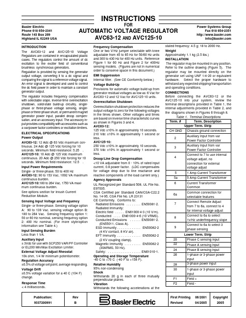
Publication:Rev First Printing 06/2001Copyright 9337200991BRevised04/20052005Basler ElectricPhone 618 654-2341Route 143 Box 269Highland IL 62249 USAPower Systems GroupFax 618 654-2351***************INSTRUCTIONSFORAUTOMATIC VOLTAGE REGULATORAVC63-12 AND AVC125-10INTRODUCTIONThe AVC63-12 and AVC125-10 Voltage Regulators are contained in encapsulated plastic cases. The regulators control the amount of dc excitation to the exciter field of conventional brushless synchronous generators.Regulation is provided by sensing the generator output voltage, converting it to a dc signal and comparing the signal to a reference voltage signal.An error signal is developed and used to control the dc field power in order to maintain a constant generator output.The regulator includes frequency compensation with selectable slope, inverse-time overexcitation shutdown, solid-state build-up circuitry, single-phase or three-phase voltage sensing, single-phase or three-phase shunt, or permanent magnet generator power input, parallel droop compen-sation, and an accessory input. The accessory in-put provides compatibility with accessories such as a var/power factor controllers or excitation limiters.ELECTRICAL SPECIFICATIONS Power OutputAVC63-12: 12 Adc @ 63 Vdc maximum con-tinuous. 24 Adc @ 125 Vdc forcing for 10seconds. Minimum field resistance: 5.25 S .AVC125-10: 10 Adc @ 125 Vdc maximum continuous. 20 Adc @ 250 Vdc forcing for 10seconds. Minimum field resistance: 12.5 S .Input Power RequirementsSingle- or three-phase, 50 to 400 HzAVC63-12: 90 to 153 Vac, 1092 VA maximum continuous burden.AVC125-10: 180 to 264 Vac, 1750 VA maxi-mum continuous burden.See options section for Inrush Current Reduction Module.Sensing Input Voltage and FrequencySingle- or three-phase. Sensing voltage option A: 90 to 139 Vac, sensing voltage option B:180 to 264 Vac. Sensing frequency option 1:50 or 60 Hz nominal, sensing frequency option 2: 400 Hz nominal. (For more style/option information see Table 4.)Input Sensing Burden Less than 1 VA.Auxiliary Input± 3Vdc for use with SCP250 VAR/PF Controller or EL200 Min/Max Excitation Limiter.External Voltage Adjust Rheostat10k ohm, 1/4 W minimum potentiometer.Regulation Accuracy±0.5% of voltage set point, average responding.Voltage Drift±0.5% voltage variation for a 40/C (104/F)change.Response Time < 4 milliseconds.Frequency CompensationOne or two V/Hz jumper selectable with knee adjustable from 45 to 65 Hz for 50/60 Hz units and 300 to 430 Hz for 400 Hz units. Reference Figure 1 for 60 Hz and Figure 2 for 400Hz sensing models. (Figures are not in numerical order to conserve space in this document.)EMI SuppressionInternal filter. (See CE Conformity below.)Voltage Build-UpProvisions for automatic voltage build-up from generator residual voltages as low as: 6 Vac for AVC63-12 and 12 Vac for AVC125-10 units.Overexcitation ShutdownOverexcitation shutdown protection reduces the output voltage to zero for the following voltages in the times shown. Other voltages and times are based on inverse time characteristic curves as shown in Figures 3 and 4.AVC63-12:125 Vdc ±10% in approximately 10 seconds.210 Vdc ±10% in approximately 1 second or less.AVC125-10:250 Vdc ±10% in approximately 10 seconds.370 Vdc ±10% in approximately 1 second or less.Droop/Line Drop Compensation<10 VA adjustable from 0 - 10% of rated input current, 0.8 power factor. (LDC compensates for voltage drop due to line reactance and reactive components of the load current only.)Agency ApprovalsUL Recognized per Standard 508, UL File No.E97035.CSA Certified per Standard CAN/CSA-C22.2No. 14-95, CSA File No. LR 23131CE Conformity. Conforms to:Radiated Emissions ........EN50081-2.Radiated Immunity:Electric field .....EN61000-4-3 (10 V/m).Conducted ....EN61000-4-6 (10 VRMS).Conducted Emissions ......EN50081-2.(EN55011, Class A).ESD Immunity .............EN50082-2(4 KV contact, 8 KV air).EFT Immunity .............EN50082-2(2 KV coupling clamp).Magnetic Immunity .........EN50082-2(30ARMS, 50 Hz).Safety:..................EN61010-1.Operating and Storage Temperature -40/C to +70/C (-40/F to +158/F).Relative Humidity 95% non-condensing ShockWithstands 20 g in each of three mutually perpendicular planes.VibrationWithstands the following accelerations at thestated frequency: 4.5 g; 18 to 2000 Hz.WeightApproximately 1.1 kg (2.5 lbs.) INSTALLATIONThe regulator may be mounted in any position.Refer to the outline drawing (Figure 5). The regulator may be mounted directly on the generator set using UNF 1/4-20 or equivalent hardware. Select the proper hardware to withstand any expected shipping/transportation and operating conditions.CONNECTIONSBefore connecting the AVC63-12 or the AVC125-10 into your system, review the terminal descriptions provided in Table 1, the internal adjustments provided in Table 2, and the diagrams shown in Figures 6 through 8.Table 1. Terminal Descriptions Term. #Term. DescriptionUpper Term. Strip CH GNDChassis ground connection 2Auxiliary Input from var Power Factor Controller 3Auxiliary Input from var Power Factor Controller 4Connect to 7 to use internal voltage adjust, noconnection for external voltage adjust5 1 Amp Current Transformer 5a 5 Amp Current Transformer 6Current Transformer Common6a Common connection for selectable features 7Connect Remote Adjust from 7 to 6a, connect to 4for internal voltage adjust 8Connect to 6a to select1v/Hz underfrequency slope 9Connect to 6a to select 3phase sensing Lower Term. Strip20Phase C sensing input 22Phase A sensing input 24Phase B sensing input 261-phase or 3-phase power input283-phase power input 301-phase or 3-phase power input F1Field +F2Field -CAUTIONDo not flash the field with the generator in motion. Regulator damage may result.CAUTIONThe factory calibration (FAC CAL)adjustment is intended for use by factory technicians only. The following procedure can be used if the factory calibration has been disturbed.Table 2. Internal AdjustmentsAdjust. Adjustment.Description DRP Voltage Droop Adjust FAC CAL FAC CAL is a factory voltageadjust range calibration. No customer adjustment is required.VLT ADJ Multi-Turn Voltage Adjust UF Underfrequency Knee Adjust STB Stability Adjust OPERATION GeneralTable 3 provides system start-up procedures for the AVC63-12 and AVC125-10 Voltage Reg-ulators. Symptoms of problems occurring during start-up that arise from incorrect regulator adjustment and certain generator system problems that resemble faulty regulation are included together with possible solutions. Simplifying the system by eliminating components, such as remote adjust poten-tiometers and other non-essential items can be helpful in the troubleshooting process. Ad-justments, options, and an operational test are included in the paragraphs after the table.Preliminary Set-UpTo prevent damage to the regulator, ensure that the regulator has been installed and connected in accordance with the paragraphs in Instal-lation and Connections before proceeding with the system start-up. System Start-UpRefer to Table 3 for system start-up.ADJUSTMENTS Field FlashingWhen the regulator is operated with the generator for the first time, the polarity of the residual magnetism may not be correct or of sufficient magnitude. If generator residual voltage is less than 6 Vac for the AVC63-12 or 12 Vac for the AVC125-10 at terminals 26,28and/or 30 shut down the prime mover and proceed with the following steps:1.With the prime mover at rest, apply a dcsource (ungrounded), of not more than 24Vdc, to terminals F1 (positive) and F2(negative) in series with a limiting e one (1) ohm of resistance for each volt from the dc power source with a power rating of least one (1) watt per ohm.EXAMPLE: If using a 24 Vdc source, use a 24-ohm, 24-watt resistor.2.Allow the field to be flashed for approx-imately ten seconds before removing the dc source.3.If voltage build-up does not occur afterperforming steps (1) and (2), verify the polarity of the dc source used in steps (1)and (2) and re-perform.Frequency Roll-Off (UF Knee) Adjustment The underfrequency knee (roll-off) is typically set below the nominal system frequencies.When the generators speed falls below the knee set point of the regulator, generatorvoltage is reduce proportional to the speed of the machine. To adjust the underfrequency knee, follow the steps below:(1)Adjust the generator frequency for nominal frequency (50, 60, or 400 Hz).(2)Adjust the underfrequency potentiometer (UF) CCW.(3)Adjust the Voltage Adjust potentiometer for nominal generator voltage.(4)Adjust the underfrequency potentiometer (UF) CW until the voltage begins to decrease.(5)Adjust the underfrequency potentiometer (UF) CCW until the voltage just returns to the value set in Step 3.(6)The underfrequency knee is now set just below the nominal operating frequency. Further rotation in the CCW direction will lower the knee frequency set point at which underfrequency compensation begins.(7)Connecting a jumper from terminal 8 to terminal 6a will provide an underfrequency slope of 1 P.U. V/Hz. No connection to terminal 8 will result in an underfrequency slope of 2 P.U. V/Hz. The slope can also be selected on the 400Hz models. However, the actual V/Hz curve is approximately 1 P.U. or 2 P.U.depending if the terminal 8 is jumpered to 6a or not.Stability (STB) AdjustmentAn oscilloscope or other voltage-recording device should be used if an optimal stability setting is desired. Adjust the stability setting with the generator at no load. Good response can be obtained with the following procedure.(1)Rotation of the front panel STB control in the clockwise (CW) direction will slow response time.(2)Rotation of the front panel STB control in the counter-clockwise (CCW) direction will speed response time. If rotated too far CCW,the generator voltage may oscillate (hunt).(3)Rotate the front panel STB control CCW until the system just begins to oscillate and then rotate CW just past the point where oscillation occurred. Apply various amounts of loads to determine proper stability performance.Voltage (VLT ADJ) Adjustment(1)Installation of a jumper across terminals 4and 7 allows the internal (front panel) VLT ADJ adjustment to vary the generator nominal voltage over the operating range.(2)Remove the jumper between terminals 4and 7 and connect a 10k ohm external voltage adjust potentiometer across terminals 6a and 7to allow operation of the external voltage adjust potentiometer. The internal voltage adjustment should be set fully CW for proper operation of the external adjustment. It should be noted, as the external potentiometer resistance in-creases, generator voltage also increases.Factory Calibration (FAC CAL) Adjustment(1)With the voltage regulator operating on a generator, adjust the calibration potentiometerfully CCW and the external voltage adjust potentiometer fully CW. Adjust the FAC CAL potentiometer CW until the generator voltage reaches the desired maximum voltage setting.The unit is calibrated and the calibration potentiometer can be sealed. Parallel Droop CompensationVariable parallel droop compensation levels can be obtained by adjusting the droop poten-tiometer. CW rotation increases the amount of droop for a given condition.Line Drop CompensationWhen the sensing input CT connections are swapped to provide LDC, the droop adjustment becomes the LDC adjustment.OPTIONSThe AVC63-12 and AVC125-10 may be equipped with the following options to enhance operational characteristics. Characteristics of these options are defined in the following para-graphs.Remote Voltage AdjustConnect a 10 k ohm, 2 watt potentiometer from terminals 6a to 7, remove the jumper from terminal 4 to 7 and adjust the internal voltage adjust potentiometer fully CW to allow operation of a remote voltage adjust.Inrush Current Reduction ModuleAn ICRM-15 (Inrush Current Reduction Module) is required when energizing the AVC63-12 and AVC125-10 from a source that is already at the regulators input power ratings.This module minimizes the amount of inrush current that could be seen when power is applied.Excitation DisableThis option provides for disabling of the excitation system by removal of power from the voltage regulator. A switch removing voltage from terminals 26, 28 and/or 30 will remove power.Excitation LimiterThis EL200 option provides an initial fast acting limit of the field current at a pre-selected level.Once the field current has changed to the selected level, the output provides a signal to the regulator to change the excitation.Var/PF ControlThis option allows the AVC63-12 and the AVC125-10 to regulate the var and power factor while the generator is connected to an infinite or utility bus. The var/PF option (Model Number SCP250G-50 for 50-hertz operation or SCP250G-60 for 60-hertz operation) supplies a dc signal into the AVC63-12 and AVC125-10terminals 2 and 3 to regulate the SCP250 var or power factor setting. (See Figure 7 for inter-connection diagram.)Current Boost SystemWith this CBS212 option, if the generator output voltage drops below the preset operation point due to a short or large motor starting, the current boost function detects the voltage drop.The function then provides full current boost to the generator exciter until the voltage returns to a level just above the operation point.Manual Voltage ControlThis option provides a manual back-upchannel for manually controlling the generator output during generator start-up and commissioning orin the unlikely event that the voltage regulator should fail. Manual voltage controller model MVC-112 is suitable for use with either the AVC63-12 or the AVC125-10 voltage regulator.Table 3. System Start-Up1.Perform the preliminary set-up.2.Start prime mover and bring up to rated speed.If the voltage does not build up:a.Flash Fieldb.Remove power for 1 minute toallow the overexcitation circuit to reset.3.Slowly adjust VOLT adjustment or external voltage adjust rheostat until voltage reaches nominal.If the voltage does not build up to therated value, check the generator output for a shorted or excessive load.4.Apply and remove load to check stability.If the generator response is too slow or is hunting (oscillating):a.Check generator output for shortedor excessive load. Adjust STB with no load applied.b.Check stability of governor system.5.Check regulation under normal operating conditions.If the regulation is poor:a.Check that the prime mover is upto rated speed.b.Check that the voltmeter isconnected at the same point as the regulator sensing.e an average sensing voltmeter(not an RMS sensing voltmeter).Table 3. System Start-Up (Continued)6.Reduce generator frequency. Generator output should decrease from this point.If the generator output voltage does not decrease at desired frequency:a.Check that all the wiring is inaccordance with the connection diagrams provided in these instructions.b.Adjust FREQ control.OPERATIONAL TESTThis test is designed to test all eight models of the AVC63-12 and AVC125-10. See Table 4for appropriate testing voltages and frequencies.To operationally test any AVC63-12 or AVC125-10, perform the following steps.a.Connect the voltage regulator as shown by Figure 9 and apply appropriate voltages.b.Adjust the front panel VLT ADJ control fully counterclockwise (CCW).RESULT: Observe that the lamp is OFF.c.Adjust the front panel VLT ADJ control clockwise (CW).RESULT : Observe that the lamp is now ON.d.Adjust the front panel VLT ADJ control until the lamp just goes out.Regulator operation is satisfactory if the above results are obtained. Stability, however, must be tested with the generator and regulator in operation.MAINTENANCEPreventive MaintenanceA periodic inspection should be made of the voltage regulator to ensure that it is clean and free from accumulations of dust and moisture. Be sure that all connections are clean and tight.TroubleshootingIn case of failure/defective operation of the unit, simplifying the system by eliminating com-ponents, such as remote adjustpotentiometers and other non-essential items can be helpful in the troubleshooting process.Table 4. Testing ParametersInput SensingModel Power Vac Freq.AVC63-12A1120120 50/60AVC63-12A2120120400AVC63-12B112024050/60AVC63-12B2120240400AVC125-10A1 24012050/60AVC125-10A2240120400AVC125-10B124024050/60AVC125-10B2240240400Figure 1. 60 Hertz Frequency CompensationFigure 2. 400 Hertz Frequency CompensationL C23Part of AVC63-12or AVC125-10Part of EL200P0009-25.vsd 06-26-01A CPart of SCP250NOTE: AVC Units may be connected to either the EL200 or the SCP250 using the terminals as shown in place of this series interconnection. See the unit Instruction Manuals for more information.Figure 7. AVC Interconnection DiagramFigure 9. Operational Test Set-Up。
调压装置培训
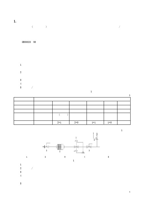
定警戒值时,切断阀自动介入将该通道关闭,避免下游系统压力异常而危及用户安全。
(5)放散阀:也是一个安全装置。其设置目的是防止紧急切断阀因非故障因素而关闭。当调压器出口
1
管道因非故障因素而压力暂时升高达到一定警戒值时,放散阀自动开启给管道卸压,压力降低至低于开启
警戒值后阀自动关闭。
较复杂的调压站除具有上述功能组件外还可包含下列各组件中的部分或全部:
较轻
较重
最轻
价格
贵
较廉
较廉
最廉
备件费用
最廉
较贵
较廉
最贵
本公司销售的调压器可按不同的原则分类如下:
3
燃气调压器
直接作用式 间接作用式
NORVAR
DIVAL
轴流式 Zetaflux
截至式
REVAL182 REFLUX819
本公司经销的调压器的型号及其参数汇总于表 1 中。 表 2 燃气调压器的性能
型号 NORVAL
DIVAL STAFLUX185
进口压力范 规格
围(MPa) DN25~80
1″~8″ 0.0.1~1.6
DN100~200 0.01~0.8
1″ 1″2″
50、100 0.01~0.5 160、250(带
切断阀) 0.01~1.6 160、250(不 带切断阀) 0.01~1.9
1~3″
~10
出口压力范围 最小压 精度 关闭压 (kPa) 降(kPa) 等级 力等级
(6)绝缘接头:作用为防止调压站内高速燃气的流动摩擦所产生的杂散电流流入地下管网而破坏其阴
极保护效果,以及降低杂散电流的干扰腐蚀。
(7)流量计:计量燃气流量。分两种,一种供计费用,一种供监察用
Norgren B07滤芯与调压器说明书

A....PTFB....ISO Rc taper G....ISO G parallel 1....1/8"2....1/4"A....0,1 to 0,7 bar (1 to 10 psig)E....0,3 to 3,5 bar (5 to 50 psig)K....0,3 to 7 bar (5 to 100 psig)A....Automatic M...Manual1....5 µm 3....40 µm Transparent..Relieving .........Without............01Transparent..Relieving .........With.................02Transparent..Non-relieving...Without............03Transparent..Non-relieving...With.. (23)B07Installation & MaintenanceInstructions CAUTIONWater vapor will pass through these units and couldcondense into liquid form downstream as air temperaturedrops. Install an air dryer if water condensation could havea detrimental effect on the application.WARNINGThese products are intended for use in industrialcompressed air systems only. Do not use these productswhere pressures and temperatures can exceed those listedunder Technical Data.Polycarbonate plastic bowls can be damaged andpossibly burst if exposed to such substances as certainsolvents, strong alkalies, compressor oils containing ester-based additives or synthetic oils. Fumes of thesesubstances in contact with the polycarbonate bowl,externally or internally, can also result in damage. Cleanwith warm water only.Use metal bowl in applications where a plastic bowlmight be exposed to substances that are incompatible withpolycarbonate.If outlet pressure in excess of the filter/regulatorpressure setting could cause downstream equipment torupture or malfunction, install a pressure relief devicedownstream of the filter/regulator. The relief pressure andflow capacity of the relief device must satisfy systemrequirements.The accuracy of the indication of pressure gauges canchange, both during shipment (despite care in packaging)and during the service life. If a pressure gauge is to beused with these products and if inaccurate indications maybe hazardous to personnel or property, the gauge should becalibrated before initial installation and at regular intervalsduring use.Before using these products with fluids other than air,for non industrial applications, or for life-support systemsconsult Norgren.。