电子罗盘HMR3000 中文手册
HMG3000中文操作手册

PORTABLE DATA RECORDERH M G 3 0 0 0Stock no.: 669712Edition: 01/2006Portable DataRecorder.Starting the HMG 3000 UpOperating Elements操作原理1On/Off button 电源开关2Brightness/contrast setting of the display显示屏明暗,对比设置3 Esc key取消,返回键For canceling an entry or going Back step by step 取消进入或一步步后退4Shift key 转换键Switches the numpad to a textpad when pressed; the textpad is active only as long as the Shift key is pressed.按转换键,数字板转换成文字板只有按转换键,文字板就能激活5Text/numeric keypad 文本或数字键盘Numbers and letters can be entered via the combination keypad in afashion similar to that of mobile phones.通过联合键盘输入数字与文本,与流行的手机键盘相似Numerals: 0 to 9; “.” (decimal separator) and“-“ (minus)数字:0-9;“.”(十进制分开)“-“ (负数)Text entry : a, b, c, ... x, y, z and A, B, C, ... X, Y, Z ins = insert; del = delete;文本输入:a, b, c, ... x, y, z 和A, B, C, ... X, Y, Z ins=插入del =删除Entry of spaces: shift + ins (simultaneously)空格输入:转换键+插入键(同时)Deletion of characters: shift + del (simultaneously)字符删除:转换键+删除键(同时)6Graphic display 显示图表Display of the menu and operating functions,measured values and measurement curves菜单显示与操作功能,测量值与测量曲线7.5-way navigation key 5通导航键For navigating step by step in the display, Ok key for inputting, concluding,accepting or storing an entry为了在显示中一步步导航,OK键用于输入,终止,接受和保存输入Tip:To accept characters: release the Shift key or press the right arrow of the 5-way navigation key提示:接受字符:释放转换键或按住5通导航键的右箭头Connectors 连接器4 sensor input jacks for up to 8 sensors with an analog signal(channel A – D and E – H*), e.g. for sensors for measuring pressure,temperature or flow rate.The four input jacks can be doubled by plugging in Y-adapters.四个传感器输入接头,加带Y接头可扩展多达八个传感器输入通道A-D和E-H)例如:测量压力的传感器,温度或流速四个输入接头通过插入Y型适配器可增加一倍1 or2 input jacks for-2 digital signals, e.g. for frequency or speed measurements (channel)-1 voltage input ( - 10 V to + 10 V, channel H*)1或2输入接头:-2数字信号,如频率或速度测量(通道I,J)-1电压输入(-10伏特到+10伏特,通道H)Female connector for power supply 电源供应接头1 USB connector 1USB接口1 serial port 1串口H*): C hannel H can be used for sensors with an analog signal as well as for voltage measurements of -10 V to +10 V.通道H能被用作于带有模拟信号的传感器还有-10伏特到+10伏特的电压测量当第一次开启设备,屏幕会出现欢迎字样。
HMR数字罗盘说明书

定向和导航 姿态参考 卫星天线位置 平台水平度 GPS 集成系统 激光侧距机
特征 方向 精度
分辨率 迟滞
重复精度
倾斜和俯仰
精度
分辨率 磁滞 重复性
测试条件
水平 0-30 度(只有 HMR3300) ± 30~60 度(只有 HMR3300)
HMR3200 HMR3300 HMR3200 HMR3300
高斯 微高斯 VDC mA mA 波特
HZ
mm 克
˚C ˚C
模块尺寸约为 37mmX25mm, 8 个针。手持模块时将有管脚内的一边对准自己并把管脚一面朝下。最左边为 PIN1。
Honeywell/Commercial Switch&Sensor 霍尼韦尔商业开关与传感器
数字罗盘 HMR3200/HMR3300
磁场计输出命令 *M<cr><lf>选择磁场计输出模式
格式:Magx,MagY,Magz
举例:1256,-233,1894
SPI(串行外围接口)接口运行模式
SPI 运行模式如下: SCK 空置低
数据输出紧跟于 SCK 下降沿后
数据采样在 SCK 上升沿前
(MODE 协议 HMR3200/HMR3300 模块控制 SCK 和 SDO 脚,主控制器控制 SDI 和 CS 脚,主控制将此 HMR 模块 CS 脚延迟 20ms 开始 SPI 通讯。HMR 模块作为响应会发送 ASCII 的“S”,主控制器同时会发送一个有效命令字符。HMR 模块将估算从主控制器 收到的命令字符;如果命令字符是被认可的并且有效,HMR 模块将传出响应的数据。在发送被请求的数据后,HMR 模块将 结束 SPI 通讯周期。如果命令是不被认可或者无效的,HMR 模块将回应一个 ASCII 的“e”,然后结束 SPI 通讯周期。
磁罗盘HMR3200HMR3300

技术规格:
参数 航向
适用条件
最小值
标准值
最大值
水平
1.0
精度
0°至±30°(仅限HMR3300)
3.0
±30°至±60°(仅限HMR3300)
4.0
分辨率 磁滞性
HMR3200 HMR3300
0.1
0.1
0.2
0.2
0.4
重复性
HMR3200 HMR3300
纵倾与侧倾(仅限HMR3300)
0.1
0.2
NAV Technology
HMR3200/HMR3300
磁罗盘HMR3200/HMR3300
霍尼韦尔HMR3200/3300型数字罗盘是一种电子式 罗盘装置,主要用于航海和导航系统。霍尼韦尔磁阻传感 器为小型的固态电子罗盘装置提供了足够的可靠性和精 确性,这类罗盘装置很容易在系统中集成,只需要使用 ASCII格式的UART或者SPI协议就可以方便地实现。
0.2
0.4
范围
纵倾与侧倾范围
±60°
精度 零位精度*
0°至±30° ±30°至±60°
水平 -20°至+70°热磁滞性能
0.4
0.5
1.0
1.2
0.4
1.0
-40°至+85°热磁滞性能
5.0
分辨率
0.1
磁滞性
0.2
重复性
0.2
磁场
范围
最大磁通量
±2
分辨率 电场
0.1
0.5
输入电压
未调制
6
15
电流 数字接口
25.4×36.8×11
重量
7.5
环境
温度
品牌:Honeywell 产品名:HMR3000 型号:HHMR3000 品牌型号说明书

Digital Compass Solution HMR3000The Honeywell HMR3000 is a digital compass module that provides heading, pitch, and roll outputs for navigation. Three Honeywell’s magneto -resistive sensors are oriented in orthogonal directions to measure the vector components of earth’s magnetic field. A fluid tilt sensor is employed to determine a gravitational reference. These solid-state sensors create a strapdown compass that is both rugged and reliable. The data output is serial full-duplex RS-232 or half-duplex RS-485 with 1200 to 19,200 data rates.Applications include: Compassing & Navigation, Dead Reckoning Backup to GPS Systems, Marine Navigation, Antenna Positioning, and Land SurveyingA RS-232 development kit version is available that includes a windows compatible demo program (does not work with RS-485 devices), interface cable, AC adapter and carrying case.Honeywell continues to maintain product excellence and performance by introducing innovative solid-state magnetic sensor solutions. These are highly reliable, top performance products that are delivered when promised. Honeywell’s magnetic sensor solutions provide real solutions you can count on.FEATURES & BENEFITS BLOCK DIAGRAMHigh Accuracy, <0.5° with 0.1° ResolutionWide Tilt Range of ±40° Up to 20 Updates per Second NMEA Standard Sentence Outputs Hard Iron Calibration RoutineRS-232 or RS-485 Serial Data Interfaces PCB or Aluminum Enclosure Options6-15 volt DC Unregulated Power SupplyInterfaceHMR3000SPECIFICATIONSPower SupplyTemperature(2) Tested at 25°C except stated otherwise.(3) Characterized(4) Parts stationary for 24 hours before testing(5) The HMR3000 Demo Kit is not available with the RS-485 interface because the software does not support half-duplex protocol2 HMR3000 3PIN CONFIGURATION(1) Power input shall only be applied to either Pin 8 (+5VDC) or Pin 9 (Unregulated +6 to+15VDC).(2) Exceeding the voltage specifications for Pin 8 may damage the HMR3000.RS-232 UNBALANCED I/O INTERCONNECTSRS-485 BALANCED I/O INTERCONNECTSHMR3000HOST PCHOST PCHMR3000HMR3000DATA COMMUNICATIONSThe HMR3000 serial communications are governed by a simple asynchronous, ASCII protocol modeled after the NMEA0183 standard. Either an RS-232 or an RS-485 electrical interface can be ordered. ASCII characters are transmitted and received using 1 start bit, 8 data bits (LSB first), no parity (MSB always 0), and 1 stop bit; 10 bits total per character. Thebaud rate defaults to 19,200 and can be reconfigured to 1200, 2400, 4800, 9600, 19200, 38400 bits per second. TheHMR3000 supports both standard NMEA 0183 and proprietary messages. Unsolicited NMEA messages are sent by theHMR3000 in Continuous Mode at the rates programmed in the EEPROM. HMR3000 also responds to all input messagesfrom the host. An HMR3000 response to a command input may be delayed due to transmission of an unsolicited output.The host computer must wait for HMR3000 to respond to the last command input before sending another command message. All communication from and to HMR3000 contain a two-character Checksum Field at the end of the data fields,and are denoted in the sentences by ‘hh’. The checksum assures the accuracy of the message transmitted. This checksumis also calculated per NMEA 0183 Standard.The RS-232 signals are single-ended undirectional levels that are sent received simultaneously (full duplex). One signal isfrom the host personal computer (PC) transmit (TD) to the HMR3000 receive (RD) data line, and the other is from theHMR3000 TD to the PC RD data line. When a logic one is sent, either the TD or RD line will drive to about +6 Volts referenced to ground. For a logic zero, the TD or RD line will drive to about –6 Volts below ground. Since the signals are transmitted and dependent on an absolute voltage level, this limits the distance of transmission due to line noise and signalto about 60 feet.When using RS-485(1), the signals are balanced differential transmissions sharing the same lines (half-duplex). This meansthat logic one the transmitting end will drive the B line at least 1.5 Volts higher than the A line. For a logic zero, the transmitting end will drive the B line at least 1.5 Volts lower than the A line. Since the signals are transmitted as difference voltage level, these signals can withstand high noise environments or over very long distances where line loss may be a problem; up to 4000 feet. Note that long RS-485 lines should be terminated at both ends with 120-ohm resistors.Specific measurement descriptions and interface commands are not included in this datasheet but are included in the companion HMR3000 User’s Guide document.(1) Demonstration software for the HMR3000 does not support the RS-485(half-duplex) protocol. The software is onlyavailable with the RS-232 interface.CIRCUIT DESCRIPTIONThe HMR3000 Digital Compass Module contains all the basic sensors and electronics to provide digital indication of headingand tilt. The HMR3000 has all three axis of magnetic sensors on the far end of the printed circuit board, away from the connector interface. The HMR3000 uses the circuit board mounting holes or the enclosure surfaces as the reference mechanical directions. The complete HMR3000 PCB assembly consists of a mother board and the 9-pin D-connector.The HMR3000 circuit starts with the Honeywell HMC1001 1-Axis Magnetic Sensor and the HMC1002 2-Axis Magnetic Sensor elements to provide the X, Y, and Z axis magnetic sensing of the earth’s field. These sensor output voltages arethen amplfied and converted to a digital representation. A microcontroller integrated circuit receives the digitized magneticfield values (readings) by periodically querying the Analog to Digital Converter (ADC) and performs the necessary offsetvalue corrections provided by the EEPROM via the calibration routine. This microcontroller also performs the external serialdata interface and other housekeeping functions. The onboard EEPROM integrated circuit also is employed to retain necessary setup variables for best performance.A liquid filled two-axis (pitch, roll) tilt sensor is also used to create tilt compensated heading data. This tilt sensor performsan electronic gimballing function and is normally mounted flat (PCB horizontal) for maximum tilt range.4 HMR3000APPLICATIONS PRECAUTIONSSeveral precautions should be observed when using magnetic compasses in general:∙The presence of ferrous materials, such as nickel, iron, steel, and cobalt near the magnetometer will create disturbances in the earth’s magnetic field that will distort the X, Y, and Z field measurements.∙Perming effects on the HMR3000 circuit board need to be taken into account. If the HMR3000 is exposed to fields greater than 10 gauss, then it is recommended that the enclosure/circuit boards be degaussed for highestsensitivity and resolution. A possible result of perming is a high zero-field output indication that exceedsspecification limits. Degaussing wands are readily available from local electronics tool suppliers and areinexpensive. Severe field offset values could result if not degaussed.NON-FERROUS MATERIALSMaterials that do not affect surrounding magnetic fields are: copper, brass, gold, aluminum, some stainless steels, silver,tin, silicon, and most non-metals.HANDLING PRECAUTIONSThe HMR3000 Digital Compass Module measures fields within 1 gauss in magnitude. Computer floppy disks (diskettes)store data with field strengths of approximately 10 gauss. This means that the HMR3000 is many times more sensitive than common floppy disks. Please treat the compass with at least the same caution as your diskettes by avoiding motors, CRTvideo monitors, and magnets. Even though the loss of performance is recoverable, these magnetic sources will interferewith measurements.The fluidic tilt sensor works best when kept near level, and in calm to moderate vibration conditions. If turned upside downor violently jarred, not all the fluid will immediately return to the bottom of the tilt sensor’s glass ampoule. Accurate til t andtilt compensated headings may be unavailable for a minute or two to allow for the fluid to transit to the bottom of the ampoule.PCB DIMENSIONS AND PINOUT 5HMR30006 CASE DIMENSIONSDEMONSTRATION PCB MODULE KITThe HMR3000 Demonstration Kit includes additional hardware and Windows software to form a development kit for the digital compass module. This kit includes the HMR3000 PCB and enclosure, serial port cable with attached AC adapter power supply, and demo software plus documentation on a compact disk (CD). The figure below shows the schematic of the serial port cable with integral AC adapter. There will be three rotary switches on the AC adapter. These should be pointed towards the positive (+) polarity, +9 volts, and 120 or 240 VAC; depending your domestic supply of power.22D9-FD9-F359359HMR3000 7ORDERING INFORMATIONFIND OUT MOREFor more information on Honeywell’s Magnetic Sensors visit us online at .The application circuits herein constitute typical usage and interface of Honeywell product. Honeywell does not warranty or assume liability of customer-designed circuits derived from this description or depiction.Honeywell reserves the right to make changes to improve reliability, function or design. Honeywell does not assume any liability arising out of the application or use of any product or circuit described herein; neither does it convey any license under its patent rights nor the rights of others.U.S. Patents 4,441,072, 4,533,872, 4,569,742, 4,681,812, 4,847,584 and 6,529,114 apply to the technology describedPDS-42005September 2015©2015 Honeywell International Inc.Honeywell12001 Highway 55 Plymouth, MN 55441。
Honeywell HMR3400 数字罗盘 说明书
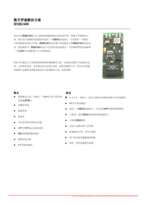
数字罗盘解决方案HMR3400霍尼韦尔HMR3400是专门为航海和精确指南应用而设计的一种数字罗盘解决方案。
霍尼韦尔的磁阻传感器技术连同一个MEMS加速度计,可以提供一个微型、可靠的倾斜补偿电子罗盘。
HMR3400使用从数字罗盘解决方案HMR3300继承而来的一套标准指令,HMR3400的设计可以使其很容易通过一个常规的5V供电电源和一个UART串行数据接口与主系统集成。
霍尼韦尔通过引入创新型的固态磁传感器解决方案,从而保证提供产品的优良品质。
正如所承诺的,这些都是具有高度可靠性、最佳性能的产品。
霍尼韦尔的磁传感器产品能够为您提供最真实可靠的解决方案,值得信赖。
特点优点►紧凑解决方案,封装在一个0.6×1.5英寸的印刷电路板(PCB)上►高精度罗盘►倾斜补偿►低成本►可以采用带式和盘式包装► -40°至+85°C运行温度范围► 8Hz持续数据刷新速率►硬铁补偿功能► 0.5°重复性精度►尺寸窄小、体积小,适用于紧密安装条件和最小布局的限制►±1°水平航向精度►使用一个MEMS加速度计,可以达到±60°的俯仰和侧滚角►大批量、商业OEM(原始设备制造商)设计►大批量OEM装配►适用于消费者和工业环境►快速航向计算,应用于指南►用户驱动的零漏磁场的校准。
►保持一致性的磁阻传感器Honeywell 技术规格参数条件标准值最大值单位最小值航向角精度水平0° 至 ±30°±30°至 ±60° 1.03.04.0度 RMS分辨率0.1 度滞后0.20.4度重复性0.20.4度俯仰和侧滚范围俯仰和侧滚范围±60 度精度 0°至 ± 30°± 30°至 ± 60 0.41.00.51.2度零精度* 水平-20°至 +70°C 热滞后-40° 至 +85°C 热滞后 0.41.05.0度分辨率0.1 度滞后0.2度重复性0.2 度磁场范围最大磁通量密度±2 高斯分辨率0.10.5毫高斯电气输入电压外部调整 4.85.05.2直流电压电流在5.0伏直流电压条件下1524毫安毫安数字接口UART ASCII(1启动, 8 数据, 1 停止, 0奇偶)用户可选择波特率2400 -19200波特数据刷新率持续/选通/平均8 赫兹连接器印制板插座(4-接点) 或 PTH 4 引脚物理尺寸电路板集成0.6 x 1.5 英寸重量 HMR3300 3.75 克环境温度工作贮存-20-55--+70+125*为了达到最佳性能,必需在使用HMR3400前进行零位调整,并经历运行温度限定范围之外的温度暴露。
SIR-3000用户手册-d 20060315
TerraSIRch SIR-3000用户手册美国地球物理测量系统公司TerraSIRch SIR-3000用户手册 (1)第一部分介绍 (1)1.1仪器配置Unpacking Your System (1)1.2概述General Description (1)硬件连接Hardware Connections (1)第二部分 启动和设置TerraSIRch (6)2.1 硬件设置Hardware Setup (6)2.2 系统启动与显示 Boot-Up and Display Screen (8)数据显示窗口 Data Display Windows (9)2.3 系统模式和菜单:概述 System Modes and Menus (10)系统菜单SYSTEM (10)采集菜单COLLECT (12)雷达Radar (12)扫描SCAN (13)增益GAIN (15)信号位置POSITION (16)滤波器FILTERS (17)回放菜单PLAYBACK Menu (18)扫描SCAN (18)处理PROCESS (19)输出菜单OUTPUT Menu (19)显示DISPLAY (19)数据传输Transfer (20)2.4: 命令栏Command Bar (20)参数设置模式In Setup Mode (20)运行模式(In RUN Mode) (22)第三部分 TerraSIRch设置采集参数 (24)3.1: 二维采集参数设置 (24)第一步:系统启动 (24)第二步: 检查参数 (24)打开参数设置文件 Load SETUP (24)测量轮标定 Survey Wheel Calibration (25)测量轮的缺省设置: (26)检查时间窗口 Check RANGE (27)检查扫描数/单位距离 Check SCN/UNIT (27)检查增益 Check GAIN (28)第三步:资料采集 (28)3.2 三维采集参数设置Setup for Single Line 3-D Collection in TerraSIRch (29)第一步:选择天线,设置参数 (29)第二步:布置测量网格 (29)第三步:测网位置信息 (29)第四步:采集数据 (29)3.3 连续测量Setting Up for Time-Based Data Collection (30)第一步:系统启动。
HMR3000数字罗盘模块解读
HMR3000数字罗盘模块解读什么是HMR3000数字罗盘模块HMR3000是一种数字罗盘模块,由Honeywell公司生产。
它可以作为导航系统中的关键组件,帮助无人机、机器人和其他导航设备方向感应和定位。
HMR3000数字罗盘模块可以测量三个轴上的磁场,并将结果转换为数字形式供设备使用。
HMR3000数字罗盘模块的特性高精度HMR3000数字罗盘模块具有非常高的精度。
它可以测量其所处的环境中的磁场,这使得导航设备可以确定方向和位置。
抗干扰HMR3000数字罗盘模块具有抗干扰能力。
它可以识别和消除环境中的噪音和干扰,从而确保测量精度的稳定性。
低功耗HMR3000数字罗盘模块拥有低功耗的特性。
这使得它可以在仅有几个电池的情况下运行数天或数周,从而成为无人机和机器人等导航设备的理想选择。
兼容性HMR3000数字罗盘模块具有高度的兼容性。
它可以与各种不同类型的设备进行通信,例如无人机、机器人和其他导航设备。
HMR3000数字罗盘模块的使用方法安装在使用HMR3000数字罗盘模块之前,需要安装它。
将其安装在需要使用导航设备的机器上,然后将接口与其他设备连接。
配置HMR3000数字罗盘模块需要正确配置以实现最佳性能。
可以使用特定软件进行配置,或通过与其他设备连接并发送命令进行配置。
实时测量一旦HMR3000数字罗盘模块正确配置,就可以进行实时测量。
其精度和稳定性将有助于导航设备准确测量方向和位置。
总结HMR3000数字罗盘模块是一款高精度、抗干扰、低功耗和具有高兼容性的导航模块。
它可以作为无人机、机器人和其他导航设备的关键组件,帮助其准确测量方向和位置。
通过安装、配置和实时测量的步骤,可以充分利用HMR3000数字罗盘模块最优秀的性能。
HMR3500数字磁罗盘套件 用户手册说明书
HMR3500数字磁罗盘套件用户手册目录1. 前言 (3)1.1 版本 (4)2. 操作原理 (4)2.1 电子硬件 (5)2.2 信号处理 (5)3. 安装 (6)3.1 罗盘安装 (6)3.2 电源 (7)3.3 线路连接 (8)4. 测试考虑因素 (9)4.1 主机 (9)4.2 磁补偿 (9)4.3 发光二极管显示器 (10)4.4 串行数据接口 (10)5. 测试软件 (11)5.1 测试软件安装 (11)5.2 演示概要 (11)5.3 启动 (12)5.4 请求和指令 (13)5.3.1 文件菜单 (13)5.4.1 视图菜单 (14)5.4.3 罗盘菜单 (16)5.4.4 罗盘自差补偿 (19)5.5.5 帮助 (21)5.5 数据记录 (21)5.5.1 文件描述 (21)6. 软件消息接口 (23)6.1 信息包(包)格式 (23)6.2 数字数据格式 (24)6.3 协议 (24)6.4 消息描述 (25)6.4.1 软件复位 (27)6.4.2 打开电源 (27)6.4.3 设置波特率值 (28)6.4.4 自检测 (29)6.4.5 状态 (30)6.4.6 刻度初始化 (30)6.4.7 设置电源上升的默认值 (31)6.4.8 磁偏差初始化 (33)6.4.9 地磁场模型-WMM (34)6.4.10 版本 (35)6.4.11 罗盘定向 (36)6.4.12 罗盘磁力补偿 (37)6.4.13 DORIENT消息传输率 (39)7. 术语和缩写词 (40)8. 参考文献 (41)插图目录图1:HMR3500数字磁罗盘电子元件 (3)图2:HMR3500数字磁罗盘模块示意图 (4)图3:工程评估套件硬件 (6)图4:安装尺寸 (7)图5:CompassHost程序主窗口显示器 (12)图6:状态浏览窗口 (15)图7:导航控制窗口 (15)图8:对话框初始化 (16)图9:磁偏差对话框 (18)图10:罗盘磁补偿过程 (20)表格目录表1:接口引出针脚的定义 (8)表2:数字数据格式 (24)表3:消息列表 (26)1.前言非常感谢阁下从Honeywell购买HMR3500数字磁罗盘工程评估成套件。
IR3000 技术手册(中文版)
IR3000 技术手册目录1.安装结构图与指南----------------------------3 5.3传感器-----------------------------261.1安装气动取样器--------------------4 5.4灯----------------------------------261.2法兰的安装结构-----------------------5 6诊断程序---------------------------------272 NIRG的通讯-----------------------------------6 6.1安装---------------------------------272.1设置电脑的以太网通讯--------------6 6.2调节主反光镜---------------------272.2 RS232通讯-----------------------------6 7修理故障----------------------------------282.3 以太网线的接线----------------------7 7.1LED和测试节点-------------------282.4 线缆装配RS232/485-----------------9 7.2以太网连接问题-------------------30 3仪器的软件设置-------------------------------93.1操作界面-------------------------------103.2设置-------------------------------------103.3设置测量-------------------------------113.3.1 测量方法--------------------123.3.2积分开始位置---------------133.3.3 积分宽度--------------------133.3.4中级过滤---------------------133.3.5平均样品---------------------133.3.6自动增益控制--------------133.3.7自动零位控制--------------133.4设置产品代码------------------------133.4.1常规参数--------------------133.4.2产品特定参数--------------143.4.3过滤--------------------------153.5设置Fieldbus-------------------------163.6设置串口和模拟输出---------------173.7以太网配置---------------------------183.8标定程序------------------------------193.8.1过程--------------------------203.8.2标定数据表-----------------203.8.3标定偏移方法--------------214操作界面/远端数字显示-------------------214.1重装操作系统------------------------214.2 LCD重新校准-----------------------224.3 配置-----------------------------------224.4 电子-----------------------------------224.5 更新软件-----------------------------234.6从因特网上更新软件---------------234.7远程显示值定标---------------------245 更换机械部件--------------------------------245.1主板/处理器/滤光转轮--------------255.1.1更换主板组件---------------255.2电源板----------------------------------26IR-3000 随机打包有2个可拆装的括号形的安装托架,它们可以被安装在不同位置以实现多样的安装方式。
Honeywell HMR3200 HMR3300型数字罗盘用户手册说明书
HMR3200/HMR3300型数字罗盘用户手册目录概述 (3)规格性能参数 (3)插脚配置 (4)电路说明 (4)结构参数 (5)应用说明 (6)UART通讯协议 (6)运行命令 (6)设置命令 (7)磁场滤波器 (8)响应命令 (8)数字表示 (9)SPI时间设定 (9)电路板模块演示套件 (10)通讯开发套件 (10)开发套件安装 (10)HMR3200型演示程序的操作 (11)HMR3300型演示程序的操作 (11)简介霍尼韦尔HMR3200/HMR3300型数字罗盘是一种电子式罗盘装置,主要用于航海和导航系统,霍尼韦尔磁阻传感器为这些小型的固态电子罗盘装置提供了足够的可靠性和精确性,这类罗盘装置很容易在系统中集成,只需要使用ASCII格式的UART或者SPI 协议就可以方便地实现。
HMR3200型数字罗盘是双轴式罗盘,既可以用于垂直方向的探测,也可以用于水平方向的探测。
HMR3300型数字罗盘是三轴式罗盘,属于可以倾斜补偿的罗盘,由于使用了双轴式加速度计,性能得到了极大的提高,倾斜角度可以达到±60°。
技术规格参数适用条件最小值标准值最大值单位航向精度水平0°至±30°(仅HMR3300)±30°至±60°(仅HMR3300) 1.03.04.0RMS 度(°)分辨率 0.1 度(°)磁滞性HMR3200HMR3300 0.10.20.20.4度(°)重复性HMR3200HMR3300 0.10.20.20.4度(°)纵倾与侧倾(仅HMR3300)范围纵倾与侧倾范围 ±60° 度(°)精度0至±30°±30°至±60° 0.41.00.51.2度(°)零位精度水平-20°至+70°热磁滞性能-40°至+85°热磁滞性能 0.41.0度(°)分辨率 0.1 度磁滞性 0.2 度重复性 0.2 度磁场范围最大磁通量 ±2 高斯分辨率 0.1 毫高斯电场输入电压未调制 6 15 直流电压电流HMR3200HMR3300 18222024mAmA参数适用条件最小值标准值最大值单位数字接口UART协议 ASCII(1启动、8数字、1停止、无奇偶校验)用户可以选择波特率2400 19200波特SPI CKE=0, CKP=0虚拟主通道更新速率连续/选通/平均HMR3200 HMR3300 158Hz连接器在线8插脚模块(间距0.1”)物理量外形尺寸电路板组件 25.4×36.8×11mm重量HMR3200HMR3300 7.257.5g环境温度工作温度(HMR3200)工作温度(HMR3300)储存温度-40-20-55---+85+70+125°C插脚配置插脚编号插脚名称描述1 SCKSPI 模式串行时钟输出2 RX/SDIUART 接收数据/SPI 数据输入3 TX/SDOUART 发送数据/SPI 数据输出4 CSSPI模式(输入)时选用跟踪侧模块5 CAL开关触发(输入)跟踪侧校正6 +5VDC*备选的+5VDC 电源(输入)7 接地电源和信号接地8 +V*未稳压的电源输入(+6 到+15VDC)*注:电路板可以用插脚6(+5VDC)或插脚8(+V)接口供电,手持模块时将插脚侧靠近自己,并将插脚朝下,则最左边为插脚1。
- 1、下载文档前请自行甄别文档内容的完整性,平台不提供额外的编辑、内容补充、找答案等附加服务。
- 2、"仅部分预览"的文档,不可在线预览部分如存在完整性等问题,可反馈申请退款(可完整预览的文档不适用该条件!)。
- 3、如文档侵犯您的权益,请联系客服反馈,我们会尽快为您处理(人工客服工作时间:9:00-18:30)。
在PC演示界面下激活 " Tune Parameters " 的菜单,(从parameter 菜单或使用Tune 按钮).
罗盘处于RUN模式下(连续输出), 没有信号传出(所有输出句子的输出速率在出厂时设置为0).
设定HPR句子的输出速率为825(Tune Page \ Serial Output),现在罗盘可以按每分钟825条句子 的速率输出航向、俯仰和横滚数据。
在Hard Iron一页,激活"Read Data",可看见"Total Valid Readings"(收集的数据点的个数) 在上升。
如果没有,可退出 Calibration一页,转到 Diagnotics \ Options \ Calibration,选择 "Real Time Data from Unit "
RS232选项
连同罗盘模块提供给客户一套PC演示接口软件,客户可以通过RS232口对HMR3000进行组态。这个软件适 用于与IBM PC兼容的计算机,带有MS Windows 3.11, Windows 95或Windows 97。允许HMR3000和PC机之间通讯,对HMR3000组态,接收罗盘的输出,记录和获得罗盘的信息。这个P C演示接口软件还可以演示输入/输出的选项,是学习了解HMR3000的重要的工具.
下面是一些可以在安装时和经常地访问的基本参数。控制磁场计操作、航向输出和报警阈值等的高级参数将 在”组态参数”(Configuration Parameters section)一节中叙述。
2.7 使用PC演示界面
激活 Tune Parameters 的按钮进行组态. (下表为安装时和经常访问的参数)
插入的标定方法 ( Built-in Calibration Method , 这种方法用于当硬铁磁场较小时)
这一方法使用迭代的过程来计算硬铁偏置.通常情况下275次迭代可以得出满意的结果.标定的过程一直继续直 到达到这一迭代次数.将HMR3000置于标定模式下 (发给命令:#F33.4=0*51<CR><lf> ) 缓慢地转动平台两周,在平台允许范围内尽可能多地变化俯仰和横滚角度.通常这一过程需进行2分钟. 通过命令 #I26C?*31<CR><lf> 来检查迭代次数.HMR3000将回答 #nnnn*hh<CR><lf> 信息,其中nnnn为迭代次数. 如果该值小于275,继续进行标定过程直到该值达到275为止。 在这一过程的最后发出指令 ( #F2FE.2=1*67<CR><lf> ) 将结果存于EEPROM中. 将罗盘返回操作模式. (发给指令: #F33.4=1*50<CR><lf>)
0<S<1 L = 整数 >1 L = 0 表示不执行
L < 256
偏向角 Deviation
偏向角
General page
罗盘的正向方向和平台的正向方向的
夹角。在罗盘的指向上加上偏向角得
± 0 - 180 ° ± 0 - 3200 mils
到平台的指向
2.8 通讯 - RS485选项
带有RS485接口的HMR3000的操作和组态通过主机的直接命令输入来完成.图2为HMR3000和计算机的连接 图。
HMR3000的输出可以被改变为包括所有六个NMEA句子或六个句子中的任意部分,每个句子可有自己的速率 。用户可以使用"Capture Mode "来捕获一段信息到某一文件中,( Diagnostics \ Options菜单) 用户还可以通过PC演示界面软件修改HMR3000的测量参数。
2.6 HMR3000的组态
HMR3000 数字罗盘模块
用户指南
2003 年 9 月 ( 注: 本册中文资料仅供参考,如有错误请以英文原版资料为准 ) 1. 概述
Honeywell的HMR3000数字罗盘模块使用磁阻传感器和两轴倾斜传感器来提供航向信息。带有电子常平架的 罗盘即000内部全部使用表面贴装元件,不含有任何的移动元 件,所以非常可靠和坚固。这个低功耗、小体积的装置带有非铁磁性金属外壳,便于安装固定在任何一个平 台上。 HMR3000便于使用,极其多样化。允许用户对罗盘的输出进行组态,包括六种NMEA标准信息的组合,改变 磁场计的测量参数以适应不同应用的需要等。 完善的罗盘自动标定程序将修正平台的磁影响。磁场计的宽动态范围 ( ±1G 或 100µT)允许 HMR3000工作在当地较大的磁场下。
缓慢地转动平台两周,在平台允许范围内尽可能多地变化俯仰和横滚角度。通常这一过程需进行2分钟。
2.3 电连接 HMR3000到计算机RS232口的连接图
未稳压的电源输入
稳压的电源输入
2.4 通讯 - RS232选项
HMR3000与外部的主机通过RS232或RS485的标准,使用简单的ASCII指令字符串进行通讯。主机可通过这 些指令直接操作HMR3000。选择RS232通讯方式,有一个对用户友好的图形接口软件,可用于对罗盘进行直 接操作。
例子: HPR输出带有磁场报警或警告条件
$PTNTHPR,218.7,N.P.1.5,N,0.8,N ** hh <cr><lf> $PTNTHPR,218.7,O.1.5,N,0.8,N ** hh <cr><lf> $PTNTHPR,P.1.5,N,0.8,N ** hh <cr><lf>
N表明正常状态 O表明磁场值高位警告(High warning) P表明磁场值高位报警(High alarm)
2.9 安装
当在你的运载工具或平台上安装HMR3000时,为获得最佳特性,需遵守下列规则:
位置:使HMR3000尽可能远离任何可能产生磁场的地点和铁磁性的金属物体.HMR3000内部的磁传感器具有 较大的磁场范围( ± 1G 或 ± 100 µT ),而地球最大的磁场为0.65G( 65uT),所以在大 多数平台上传感器不会饱和,罗盘内部的标定和补偿程序可以有效地补偿附加在地磁场上的静态磁场,但不能 对交流或直流电流产生的变化的磁场进行补偿。
激活 Display \ View 界面,Display \ Monitor NMEA Sentences 界面来看输出。
Diagnostics \ View Log 是另一种检查罗盘数据的选择。注意要使" Log all messages “ 选择被 激活(在Diagnostics \ Options 菜单中的logging一页).
RS-232 to RS-485 B&B Electronics #485TBLED
TD RS-232 RD GD
SD Control Echo off
2 RD 3 TD 7 GD
Shield 1 TD(A) 2 TD(B) 3 RD(A) 4 RD(B) 5 GND 6 +12V 7
RS-485
(B) 2 (A) 3
2.5 得到HMR3000的输出的数据
当电源和接口电缆连接好,软件在PC机中安装好以后,便可以开始从HMR3000获取罗盘数据了。
在PC演示软件的窗口下双击图标,选择相应的COM口和19200波特率. (工厂设定为19200).
在屏幕上将会出现信息块,表明微程序语言的版本,出现这一信息块表明安装和连接正确。
名称 TxD/A RxD/B GND 6 - 15V
5V
In / Out Out In In In In
针号 2 3 5 9 8
说明 RS232发送 / RS485发送-接收信号 RS232接收 / RS485发送-接收返回 电源和信号的公共地 未稳压的电源输入 经过稳压的电源输入
HMR3000在平常操作时的管脚定义 注意:在8脚上加的电压不要超过+5.5V,以免对元件造成损坏。
GND 5 Pwr 9
VAC
+12VDC
DB9 socket connector
RS-485
GND +12V
图2
RS485 和计算机的连接
HMR3000罗盘模块的RS485接口为半双工,即发射和接收电路使用同一对传输线。HMR3000必须禁止它的 发射器允许接收来自主机的字符。如果罗盘工作在" Run"的模式下,例如产生重复 的输出,那么" Run / Stop "的插脚(第6号插脚)在主机试图发送命令前应强制其为低电平(见“ 硬件 中断”一节的叙述)。
2.2 安装
对于演示装置,接口和电源电缆包括在其中(参见“电连接”一节)
对于其它的HMR3000选型,用户自己应按照下表制作带有标准9针母接头电缆。电源只接到第9针或第8针上 。对于多数应用,连接好表 1中所列出的几个管脚就可以了,而第1、4、6和7针 在HMR3000的工作中执行特定的功能,平时应保持其开路(维持逻辑高电平)
Output Message CCD的NMEA句子输出速率(单位是每
0 - 1200 / min
and Rate
分钟句子数目)
数据滤波器
TC1和TC2
0 - 255
Data Filters
用于IIR滤波器1和2的连续的时间常数
1 = 72 ms
航向输出
L和S
Heading Output 非线性滤波器的平滑系数
2.10 标定
所有的磁罗盘必须标定,来补偿地磁场外的其它磁场,以获得精确的航向。地磁场外的磁场是由主平台产生 的,因此与罗盘的安装位置有关。通过执行一个简单的程序,HMR3000可以补偿 诸如硬铁磁场的静态环境磁场,经标定程序发现的磁场分量对于罗盘的特定的位置和方向是有效的。如果罗 盘改变了安装位置或平台的磁特性发生了变化,罗盘需重新标定,否则会产生航向误差。