
HECMAC海克程控节能开水机使用说明3
G型热水工程控制仪说明书中文版

太阳能热水工程控制仪说明书蓝达牌LTY—G型工程数控仪采用高品质的元件材料及融合最新的微电脑控制技术制造而成。
本手册内容包括数控仪的安装、参数设定、异常诊断、排除及日常维护等相关事项。
为了确保正确安装及使用整个热水系统,请在装机之前,详细阅读本使用手册,并妥善保存及交由该系统的使用者。
本数控仪为精密的电力电子产品,为操作者及系统的安全,请务必交由专业的电器工程人员安装、调试,若有任何疑虑的地方请联系我们或我们的经销商,我们的专业人员会乐于为您服务。
危险!1、实施配线前请务必关闭电源。
2、切勿自行改装箱内电路。
3、箱子外壳务必正确地接地。
4、请选择安全的区域来安装数控仪,防止高温及日光直接照射,避免湿气和水滴的泼溅。
一、安装环境:△无水滴、蒸气、灰尘及油性灰尘的场所。
△无腐蚀、易燃性的气体、液体。
△坚固无振动的场所。
△使用环境温度为-30℃~40℃。
二、功能G型工程数控制仪专为太阳能或热泵(即空气源)热水系统开发、设计并制造,具以下功能:1、水位控制:能控制水位的上限水位(最高水位)和下限水位(最低水位),分五档:100%、80%、50%、30%和缺水。
在上、下限水位之间进行定温加水,即水箱水温到达设定值(如50℃)时加水,低于设定值2℃(如50-2℃)时停止加水。
2、集热循环:把水箱和集热器进行强制循环,当集热器温度高于水箱温度到设定值时(5~25℃),会自动启动集热循环,把太阳能集热器内的热水收集于水箱,在热泵系统时用于热泵的开停控制。
3、辅助电加热或其他热源(即“加热”):当太阳能不能满足需求时,可以进行辅助电加热或其他热源:可以手动进行,也可以定时进行辅助加热。
热泵系统时,当环境温度低于某一设定值时(如8℃),辅助电加热可以自动开启。
4、用水管道循环:在用水管道末端,装上温度探头,进行定温管道循,管道循环可以手动,也可以定时,在定时时间范围内,管道末端将保持设定的水温,使用户一开就有热水。
水控系统使用说明书

目录
前言................................................................................................................................. 1 一、系统介绍................................................................................................................... 1
为了节约水资源,我公司生产的红外水控,可以很好的为公司,工 厂,学校等企业各类 人群提供一个节水设备,从而增强人们的节水意识,又能节约水资源成本。
我公司的推出的智能红外水控具有计费准确、控制灵活、使用方便的特点。从而达到“按
需用水、合理消费、智能管理”。
一、系统介绍
1 、 系统组成
·安装有水控管理软件的 PC ·水控机 ·水控电源 ·发卡器 ·电磁阀 ·流量表(可选) ·485 转换器及连接线(联机下使用) ·IC 卡
智能水控器应用于已采用一卡通系统的学校、企事业单位,安装在有水龙头流水的场所。 当用户将卡放置到水控器卡感应区,读卡芯片就会获取卡上的信息,并将相关数据发送回单 片机,由单片机控制数码管显示用户余额,再对余额进行判断看是否大于单位扣费金额,若 余额足够则控制电磁阀打开,出水,流量传感器将流经的水转换成电脉冲信号输入单片机, 之后单片机通过预设费率将用水量转换成金额并进行扣费,数码管动态实时显示用户当前金 额。当卡拿走后,单片机自动关闭电磁阀,停止供水,水控器随即进入待机状态,仅显示当 前机号。卡消费信息可通过上位机软件发送指令来查询
ecocirc 自动型热水循环器说明书
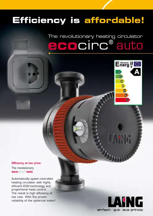
Efficiency at low price:The revolutionary eco circ ® auto .Automatically speed controlled heating circulator with highly efficient ECM technology and proportional head control.The result is high efficiency at low cost. With the provenreliability of the spherical motor!Efficiency is affordable!The revolutionary heating circulatoreco circ ®autoHighly efficient heating pumps®Save twice. Profit twice.Approximately 10 to 15 percent of the electricity consumpti-on of an average household is caused by heating circulators. More efficient circulators therefore can contribute signi-ficantly to energy savings efforts.The Ecocirc ®auto is setting new standards here: It is the first speed controlled heating circulator with energy effici-ency class A and spherical motor technology. In the design of the Ecocirc ® auto, a lot of adjustment possibilities were skipped in exchange for a better price-performance relation, but not the high efficiency of the electronically commutated permanent magnet motor (ECM technology). The flow rate dependent differential pressure control adjusts the pump performance continuously and automatically to the require-ments of the heating system: When thermostatic valves close, the pump performance is reduced to save energy and to avoid noise problems. An adjustment dial allows for mat-ching the pump performance to the respective system.The low initial cost of a standard circulator and the low con-sumption result in double savings: Economic operation and reasonable price. Efficiency at a low price. Save twice. Profit twice. With the reliability of the spherical motor .Fields of applicationThe speed controlled heating circulators Ecocirc ®auto are designed for use in hydronic heating systems.Improved efficiency due to electronic commutation (ECM)Technical dataMotor designelectronically commutated shaftless spherical motor withpermanent magnet technology Max. system pressure 6 barElectrical supply 200 – 240 Volt, 50 / 60 HertzSuitable for the following liquids: heating water VDI 2035water/glycole mixtures* Temperature range -10 °C** to +95° C Power consumption series E4: 9 – 35 Wattseries E6: 9 – 63 Watt ProtectionIP 44Insulation classF* check hydraulic performance with more than 20% glycole**non-freezingFlow rate dependentdifferential pressure control with LED indicatorThe Laing spherical motor designThe heating circulator Ecocirc ®auto uses the spherical motor principle invented by Laing. The only moving part is a ball shaped rotor/impeller unit which rides on an ultra hard ceramic bearing ball. Shaft seals or a conventional bearing bushings with a shaft have been eliminated. The only self realigning bearing in the small pump market has many advantages:long term quiet operationAn increase in noise level caused by increasingbearing play can not happen with this design. Therefore the pump can be operated for many years up to the end of the built-in wear path and the noise level will stay constantly quiet throughout this time.reliable and blockage freeThe touching surface of the bearing on the ball is very small. The torque required for starting the pump is minimal. Laing heating circulators start reliably even after the seasonal shutdown without the need for service. The spherical motor principle does not require a manual unblocking device.The heating circulator Ecocirc ® auto combines the Laing spherical motor principle with the advantages of the energy efficient electronic commutation. Rotor impeller unitThermal barrierE-coatedcast iron housingHeating circulator Ecocirc ® autoDesignStator/pump motorElectronic commutation results in significant energy savings with the same performance. The basis for the higher effici-ency is the permanent magnet rotor . The magnetic field required in the rotor does not have to be created while incurring losses, but it is permanently there.A microprocessor installed in the pump creates a rotating magnetic field with variable frequency in the stator coils (electronic commutation), which turns the rotor . Compared to state of the art pumps even higher rpm are possible, resulting in higher performance in a smaller package. The starting torque, too, is significantly increased.An additional advantage of the electronically commutated spherical motor pump is that both the coils and the electro-nics transfer the majority of their heat into the water instead of venting it off as waste heat.A further reduction in heat losses can be achieved by usingthe optional insulating cover for the pump housing. It is made of EPP , heat resistant up to 120° C, easily recycled and therefore environmentally sound.Compared to standard circulators, electronically commu-tated pumps save energy at full load, but especially when running at reduced rpm.Electronically commutated spherical motor pumps can be speed adjusted over a very wide range:ControlAll Ecocirc ® auto pumps are equipped with a control which adapts the pumps steplessly and automatically to the system requirements. When thermostatic valves close, the pump performance is reduced to save even more energy. Additional adjustment possibilities were omitted on purpose in favour of a better price-performance relation – but not the high efficiency. With this, the new Ecocirc ® auto can measu-re up to the best.The green LED in the transparent knob gives information about the operational status of the pump.eco circ ® autoAccessories, components and spare partseco circ ModelE4auto-15/130 G E4auto-20/130 G E4auto-25/130 G E4auto-25/180 G E4auto-32/180 Geco circ ModelE6auto-15/130 G E6auto-20/130 G E6auto-25/130 GDimensional drawings heating pumps Ecocirc ® autoLaing GmbH · Systeme für Wärmetechnik · Klingelbrunnenweg 4 · 71686 Remseck · GermanyPhone: +49 (0) 7146/93-0 · Fax: +49 (0) 7146/93-33·E-Mail:*************·Internet:ing.de21052008 S u b j e c t t o c h a n g e w i t h o u t n o t i c e .®®®P u m p h e a d (Flow rate (m 3/h)。
GPU 中 央 系 統 儲 水 式 電 熱 水 器 使用 手冊说明书

GPU在使用之前請詳細閱讀「使用說明書」及「保用條例」,並妥為保存。
Please read these instructions and warranty information carefully before use and keep them handy for future reference.Central Storage Electric Water Heater中央系統儲水式電熱水器目錄 Table of Contents注意 ATTENTION !安裝此熱水器時,必須依照第9-10頁的「重要注意事項」及「安裝注意事項」。
When installing this water heater, please observe WARNING and INSTALLATION REQUIREMENTS listed on P.9-10.內膽結構 Inner Tank Material採用長期耐高溫及受高壓容器專用之日本特殊不銹鋼製造,內膽結構堅固,保證防銹、耐壓及不受水質侵蝕。
Constructed of Japanese heavy gauge stainless steel, specially made for high temperature and pressure applications. It is durable and free of rust, corro-sion, deformity and hassle.保溫Thermal Insulation完密噴注式保溫層,採用高密度合成樹脂纖維絕熱法保持溫度,失溫程度達至最低,保持熱水溫度。
Maximum thermal insulation is achieved by high-density polyurethane foam injection moulded or by a 2” thick fibreglass blanket between the inner tank and outside casing.發熱管Heating Element德國原廠優質不銹鋼發熱管,獨立功率由 1.5千瓦至 12千瓦,符合各種不同之熱水要求。
海洛克加热器产品说明书

Hydronic Unit Heater Steam Rig HeaterThis manual covers installation, maintenance,repair, and replacement parts.Industrial GradeHeat-Exchanger Unit HeatersPart No. SRH2HUH2-NA-OM-APrinted in CanadaWARNING!Please adhere to all instructions published in this manual. Failure to do so may be dangerous and may void your warranty.The heat-exchanger core is not field repairable.Contact factory for a replacement core if fluid leakage occurs.^ NEMA motors are to be operated at ±10% of the nameplate voltage. If the motor is marked 208-230V the tolerance must be calculated from 230V. If the motor is marked 230V it is still suitable for 208V operation but the tolerance must be calculated from 230V. For 3-phase motors the line to line full load voltage must be balanced within 1%. †Thread-on fittings. Shipped loose and must be installed on site. C3 connection also includes C2 connection. ◊ Other voltages / frequencies available upon request. Longer lead times may apply. Contact factory* Standard Marathon NEMA ex-proof motor is suitable for Class I & II, Div. 1 & 2, Groups C, D, F & G; T3B.Heater Model Code & Option CodesModel CodingModel CodeOption CodesPhysical Dimensions (36 inch model)Model12"16"20"24"30"36"Fan Diameter inch (mm) 12 (304.8) 16 (406.4) 20 (508.0) 24 (609.6) 30 (762.0) 36 (914.4) Air Delivery* CFM (m 3/hr) 1090 (1852) 1650 (2803) 3000 (5097) 3800 (6456) 5500 (9344) 8350 (14186)Approx. Air Velocity* FPM (m/s) 1305 (6.6) 1111 (5.6) 1309 (6.6) 1138 (5.8) 1066 (5.4) 928 (4.7) Air Throw* @ 15 psi steam ft (m) 45 (13.7)65 (19.8)70 (21.3)80(24.4)85 (25.9)70 (21.3)Motor Power HP (Watts)1/4 (186) or 1/3 (248) 1/2 (373)1/2 (373) 3/4 (559)1 (746)Rec. Min. Mounting Height ft (m) 7.5 (2.3) 7.5 (2.3) 7.5 (2.3) 7.5 (2.3)7.5 (2.3)7.5 (2.3)Specifications By Model Size - North American Heaters - 60Hz* At 70°F (21°C), 60 Hz and sea level.Pressure Equipment Approvals SRH2: North America - CRN: 0H14931.2C - steam.HUH2: North America - CRN: 0H14933.2C - steam or fluids.Heater Core Maximum Pressure Rating SRH2 = 150 psig (1034 kPa). HUH2 = 400 psig (2758 kPa).Heater Core MaximumDesign Temp.550 °F (288°C).Heater Core Minimum DesignMetal Temp.-20°F (-29°C).Cabinet Material 14-gauge (0.075") (1.9 mm) steel. 36" model is 12-gauge (0.105") (2.7 mm) steel. Epoxy/polyester powder coated.Louver Blades Anodized extruded aluminum.Fan Spark-resistant aluminumFan Guard Split design with close wire spacing. A Ø3/8" (9.5 mm) probe will not enter.Motor Drive Thermally protected permanently lubricated ball bearing type. (36" model comes with maintenance free speed reducer).Mounting Holes 5/8"-11 UNC: 4 holes at top of heater (12" model has only 2 holes).Fluid Connections Standard: 2" NPT female inlet and outlet (configuration of fluid connection locations can be reversed by rotating the core). Other connection types are available (see model code chart).Header Material 12 gauge (0.105")(2.7 mm) and 3/16" (4.8 mm) carbon steel plate conforming to ASME requirements.Finned Tubes 5/8" (15.9 mm) outside diameter [16-gauge, 0.065" (1.6 mm) wall thickness] carbon steel tubes with 1-1/2" (38.1 mm) outside diameter copper-free, L-foot, tension-wound aluminum fins @ 10 fins per inch.General SpecificationsSRH2 Heaters 12" 16" 20" 24" 30" 36" Net Weight (no options) Lbs (kg) 88 (39.9) 106 (48.1) 149 (67.6) 210 (95.3) 257 (116.6) 482 (218.6) Shipping Weight (no options) Lbs (kg) 138 (62.6) 158 (71.7) 207 (93.9) 275 (124.7) 332 (150.6) 594 (269.4) with 2” NPT nipples (add) Lbs (kg) 1 (0.4) 1 (0.4) 1 (0.4) 1 (0.4) 1 (0.4) 1 (0.4) with flanges & nipples (add) Lbs (kg) 14 (6.3) 14 (6.3) 14 (6.3) 14 (6.3) 14 (6.3) 14 (6.3) HUH2 Heaters12" 16" 20" 24" 30" 36" Net Weight (no options) Lbs (kg) 88 (39.9) 106 (48.1) 149 (67.6) 210 (95.3) 264 (119.7) 491 (222.7) Shipping Weight (no options) Lbs (kg) 138 (62.6) 158 (71.7) 207 (93.9) 275 (124.7) 339 (153.7) 603 (273.5) with 2” NPT nipples (add) Lbs (kg) 1 (0.4) 1 (0.4) 1 (0.4) 1 (0.4) 1 (0.4) 1 (0.4) with flanges & nipples (add) Lbs (kg) 14 (6.3) 14 (6.3) 14 (6.3) 14 (6.3) 14 (6.3) 14 (6.3) Weights - North American Heaters12" 16" 20" 24" 30" 36"Front of Heater (dBA)3 feet 78 78 83 82 90 82 10 feet 71 73 76 76 83 76 15 feet 70 70 74 74 81 74Rear of Heater (dBA)3 feet 78 78 83 82 89 80 10 feet 71 72 77 75 83 76 15 feet 70 71 75 74 81 74ModelNoise Data By Model Size - North American Heaters - 60HzConditions For Safe Use1. Remove any dirt / dust from heater cabinet using a damp cloth to mitigate electrostatic charge buildup.2. Do not install the heater in an environment which could potentially cause an electrostatic charge buildup on the cabinet (i.e. exposure to high pressure steam).3. The heater core is NOT field repairable. All defective cores must be replaced with a factory suppliedunit.4. The motor is NOT field repairable. All defective motors must be replaced with a factory supplied orfactory approved unit.5. Flameproof joints are NOT field repairable. Any damaged enclosures/fittings will have to be replacedwith factory approved units.6. For any field repairs use only original factory installed fasteners or factory supplied replacementfasteners.— INSTALLATION —These instructions are to be used as a general guideline only.LocationPlease follow guidelines below for optimum heating results:1. Do not install heaters such that airflow is blocked or impeded by equipment or walls.2. For occupant comfort, position heaters so that air discharge is directed across areas of highest heat loss,such as doors, windows, and outside walls.3. For large areas, arrange heaters such that the air discharge of one heater is directed towards the inlet of thenext heater. This sets up a rotational airflow with air circulation in the central area of the building.4. For equipment freeze protection, direct air discharge at required equipment.5. For large workshops or warehouses it may be acceptable to use fewer, but larger heaters.6. Do not direct air discharge towards a room thermostat.7. Heater inlet and outlet coupling connection locations can be reversed in the field by removing the core,rotating it 180 degrees, and then re-installing it. Cabinet plugs can then be repositioned.Mounting1. A variety of mounting brackets are available from the factory to aid in installation.2. The heater is designed to be installed in an upright and level position. While it may be installed in otherpositions, for steam service, the inlet must be above the outlet and the bottom of the heat exchanger must drain towards the outlet.3. Heaters are designed to be suspended from the top of the cabinet using either two or four 5/8"–11 UNCbolts or threaded rod.4. It is essential that adequate structural support be provided for installation. The mounting structure must bestrong enough to support the heaters weight, provide sufficient stiffness to prevent excessive vibration, and withstand all probable abusive situations such as transportable installations where truck off-loading impacts, etc. may occur.Mounting Heights and Clearances1. To ensure that warm air reaches the floor, heaters are usually mounted 7-1/2 ft. (2.3m) to 12 ft. (3.6 m)above the floor. Heaters may be mounted at higher elevations and still provide warm air at floor level however, the maximum mounting elevation at which this occurs depends on location and operational conditions.2. Louvers may be adjusted to provide greater downward deflection of the discharge air. However, it isrecommended that louvers not be set <15° from the closed position.Fan Clearance1. Verify the minimum required clearance between fan blades / fan shroud and the fan blades / fan guard priorto heater power up.Heater Size 12" 16" 20" 24" 30" 36"Min Clearance 2.0 mm 2.0 mm 2.5 mm 3.0 mm 3.8 mm 4.6 mm— Piping Practices —1. Steam unit heaters condense steam rapidly, especially during warm-up periods. The return piping must beplanned to keep the heat-exchanger’s core free of condensate during periods of maximum heat output, and steam piping must be able to carry a full supply of steam to the unit heater to take the place of condensed steam. Adequate pipe size is especially important when a unit heater fan is operated under on-off control because the condensate rate fluctuates rapidly.2. Heater is to be connected and serviced only by qualified personnel. For additional piping information referto local codes.3. Eliminate pipe stress by adequately supporting all piping. Do not rely on heater to support piping.4. Take off all branch lines from the top of steam mains, preferably at a 45° angle, although vertical 90°connections are acceptable.5. Pipe the branch supply line into the steam unit heater’s inlet at the top and the return branch line from theoutlet at the bottom. The heater’s inlet and outlet coupling connections can be reversed in the field by rotating the heat-exchanger core. Refer to Page 10, Heat-Exchanger Core AssemblyReplacement.6. In steam systems, the branch from the supply main to the heater must pitch down towards the main and beconnected to its top in order to prevent condensate in the main from draining through the heater. In long branch lines, a drip trap may be needed.7. Allow for pipe expansion to prevent excessive strain on the unit heater’s heat-exchanger core.8. The return piping from steam unit heaters should provide a minimum drop of 10" (254 mm) below theheater so that the pressure of water required to overcome resistances of check valves, traps, and strainers will not cause condensate to remain in the heater.9. In steam systems, where horizontal piping must be reduced in size, use eccentric reducers that permit thecontinuance of uniform pitch along the bottom of piping (in downward pitched systems). Avoid using concentric reducers on horizontal piping, because they can cause water hammer.10. Installing dirt pockets at the outlet of unit heaters and strainers with 0.063 in. (2 mm) perforations to preventrapid plugging are essential to trap dirt and scale that might affect the operation of check valves and traps.Strainers should always be installed in the steam supply line if the heater is valve controlled.11. In steam or hot water systems, rapid air removal is required because entrained air is a cause of corrosion.Hot water systems should be equipped with suitable air vent valves for rapid and complete air removal at high points, at the top of each unit heater, and ends of both supply and return mains. Proper air venting for steam systems can be achieved by use of a steam trap with an internal air vent.12. Steam traps must be located below the outlet of the unit heater. Consult the trap manufacturer for specificrecommendations. Each steam unit heater should be provided with a trap of sufficient size and capacity to pass a minimum of twice the normal amount of condensation released by the unit at the minimumdifferential pressure in the system. Trap capacity is based on the pressure differential between supply and return mains. Steam systems should be equipped with a float and thermostatic trap or inverted bucket trap with an air bypass.13. If the condensate return line is above the heater outlet or is pressurized, install a check valve after thesteam trap and a drain valve at the strainer to drain the system during the off season.14. Install pipe unions and shut-off valves at connection points of each unit heater to allow maintenance orreplacement of unit without shutting down and draining the entire system. For hot water systems include a balancing valve in return line for flow regulation. A drain valve should be provided below each unit heater to allow removal of water from the heat-exchanger core if located in an area subject to freezing.15. Adequate air venting is required for low-pressure closed gravity systems. The vertical pipe connection tothe air vent should be at least 3/4" NPT to allow water to separate from the air passing to the vent. If thermostatic instead of float-and-thermostatic traps are used in vacuum systems, a cooling leg must be installed ahead of the trap.16. In high-pressure systems, it is customary to continuously vent the air through a petcock unless the steamtrap has a provision for venting air. Most high-pressure return mains terminate in flash tanks that are vented to the atmosphere. When possible, pressure reducing valves should be installed to permit operation of the heaters at low pressure. Steam traps must be suitable for the operating pressure encountered.17. On steam systems where the steam supply to the unit heater is modulated or controlled by a motorizedvalve, a vacuum breaker should be installed between the unit outlet and a float and thermostatic trap.Heat-Exchanger Core Assembly Replacement1. Heat-exchanger core assemblies are heavy and replacement requires two people for safety reasons.2. It is not necessary to dismount unit heater from its support structures to remove the heat-exchanger core assembly. However, it may be advisable in some instances to allow for core assembly removal at ground or bench level.3. Remove the bottom heater cabinet cover which is attached with 6 screws and 3 bolts.4. Support the heat exchanger core assembly, then remove the 4 core bolts on each side of the cabinet (36" models have 6 core bolts).5. Lower the core assembly from heater.6. Reverse the procedure to install replacement core and tighten 4 core bolts to 90 in-lbs (10 N-m) torque, bottom panel screws to 28 in-lbs (3 N-m) , and fan panel bolts to 100 in-lbs (11 N-m) . (36" models have 6 core bolts)Fan, Fan Guard or Motor Replacement1. For replacement of fan or fan guard remove the 4 bolts holding motor to the motor mount. For 36" modelsalso remove speed reducer bolts. If replacing motor only on 36" models, only remove motor mounting bolts and C-face flange bolts.2. Detach two-piece fan guard assembly by removing top and bottom screws that attach the fan guard to thecabinet.3. Remove fan guard pieces through top or bottom. Due to stiffness of fan guards, you may need to removeouter two top or bottom bolts that attach the fan panel to the top or bottom cabinet panels to provide sufficient clearance.4. Lift the motor, (and speed reducer for the 36" model) and fan assembly off the motor mount.5. Loosen fan hub screw and remove fan blade from motor shaft.6. To reassemble, position fan on motor shaft with end of shaft even with face of hub. Ensure the set screw isfacing towards motor and lined up perpendicular to factory-ground flat on motor shaft. This flat is our “Easy-Off” fan blade replacement feature and only comes on motors purchased from Hazloc Heaters. Tighten set screw to 150 in-lbs (17 N-m) torque.7. Place motor, (and speed reducer for the 36" model) and fan assembly onto motor mount and fasten the two-piece fan guards to the cabinet.8. Center fan in the fan-shroud opening. The gap between the fan blades and fan shroud should be even forall fan blades. Ensure the minimum gap is maintained for all blades. See page 6 for minimum gap values. 9. Bolt motor (and speed reducer for the 36" model) to motor mount, tighten nuts to 250 in-lbs (28 N-m)torque. Manually spin the fan blade to ensure it rotates freely before reconnecting heater to power supply. Fan must rotate counterclockwise when viewed from rear of heater.— Repair and Replacement —Item (in-lbs)Fan blade set screw 1505/16 - 18 UNC motor nuts 250 1/4 - 20 UNC core bolts90 Torque Settings1/4 - 20 UNC fan panel bolts 100 5/16 - 18 UNC motor mount bolts 250 #10 - 24 UNC bottom panel & louver blade screws281/4 - 20 UNC fan guard self tapping screws 100 (N-m) 17 28 28 11 11 10 3Note: Heater inlet and outlet coupling connection locations can be reversed in the field by removing the core, rotating it 180 degrees,and then re-installing it. Cabinet plugs can then be repositioned.Item No.Description12 inch16 inch20 inch24 inch30 inchPart NumberPart NumberPart NumberPart NumberPart Number*** Please have heater model & serial number available before calling ***1 Core Kit Contact factory with heater model, size, number of passes and connection typePart #’s 1119 thru 11392 Louver Blade kit 1145 1146 1147 1148 11493 Motor Mount Kit 1151 1152 1153 1154 1155 4 Fan Guard Kit 1157 1158 1159 1160 1161 5 Fan - 5/8 inch hub 116311651167116911716 Motor Kit - 5/8 inch shaft Specify motor voltage, phase, frequency, horsepower and type of enclosure (general purpose or explosion-proof)7 Thread-on 2 inch NPT Nipple1176 8Thread-on 300# Raised Face Flange1177Note: Inlet and outlet couplingconnection locations can be reversed in the field by rotating the core.*All replacement part kits include fasteners12 inch to 30 inch models12 inch to 30 inch modelsItem No.Description36 inchPart Number*** Please have heater model & serial number available before calling ***1Core Kit Contact factory with heater model, size, number of passes and connection typePart #’s 1141 thru 11442Louver Blade Kit 11503 Motor Mount Kit 11564 Fan Guard Kit 1162 5Fan - 5/8 inch hub 11736 Motor Kit - 5/8 inch shaft Specify motor voltage, phase, frequency, horsepower and type of enclosure (general purpose or explosion-proof)7Thread-on 2 inch NPT Nipple 11768 Thread-on 300# Raised Face Flange1177 9Speed Reducer Kit1178Note: Inlet and outlet couplingconnection locations can be reversed in the field by rotating the core .*All replacement part kits include fasteners36 inch model36 inch modelRegular inspection, based on a schedule determined by the amount of dirt in the atmosphere, assures maximum operating economy and heating capacity.Annual Inspection (before each heating season)1. Check all terminal connections, electrical conductors, glands and cables for damage, looseness, defects,fraying, etc. and replace or tighten where applicable.2. Check for fluid leakage from heat-exchanger core. If fluid leakage occurs, remove heater from service andhave the heat-exchanger core replaced by a factory replacement unit. Refer to “Repair and Replacement” section for complete details. Note: This heat-exchanger core is not field repairable.3. Check electrical junction box. Inside of enclosure must be clean, dry, and free from any foreign materials.The cover must also be completely on and tight.4. Check motor shaft bearing play. Replace motor if play is excessive or if motor does not run quietly andsmoothly. Motor bearings are permanently lubricated.5. On 36" models, speed reducer is maintenance free. Check for excessive noise and vibration.6. Check fan. Replace immediately if cracked or damaged. Check the gap between the fan and fan shroudmeets the minimum spacing requirement.7. Check louvers. Louver screws should be tight. Louvers are not to be set <15° of the closed position.8. Check the tightness of all hardware. All nuts and bolts, including mounting hardware, must be tightened totorque settings on Page 10.9. Turn heater motor on for a minimum of 10 minutes. Check for air exiting heater through louvers and smoothrunning of the motor and fan assembly.Periodic Maintenance (before and as required during heating season) 1. Clean the following (remove dust using compressed air):∙ Finned tubes ∙ Fan∙ Fan Shroud ∙ Fan Guard ∙ Motor ∙ Louvers ∙ Cabinet 2. Check the following:∙ Motor / fan assembly (and speed reducer on 36" models) for smooth and quiet operation. ∙ Louvers for proper angle and tightness. ∙ Electrical junction box covers are secure.∙Gap between the fan blade / fan shroud and the fan blade / fan guard meet the minimum spac-ing requirement (see page 6 for minimum values).— Maintenance Program —Date of Maintenance PerformedByMaintenance PerformedDate of Maintenance PerformedByMaintenance PerformedPRINTED IN CANADA ©Copyright 2018The information contained in this manual has been carefully checked and verified for accuracy. Specifica-tions subject to change withoutnotice.Hazloc Heaters is a trademark ofHazloc Heaters Inc.#1, 666 Goddard Ave. NE Calgary, Alberta T2K 5X3 CanadaTel.: +1-403-730-2488 Fax: +1-403-730-2482Customer Toll Free (U.S. & Canada): +1-866-701-Heat (4328) Limited 18-Month WarrantyHazloc Heaters TM warrants all SRH2 & HUH2 series of heat-exchanger unit heaters against defects in materials and workmanship under normal conditions of use for a period of eighteen (18) months from date of pur-chase based on the following terms:1. The heater must not be modified in any way.2. The heater must be stored, installed and used only in accordance with the owner’s manual and attached data plate information.3. Replacement parts will be provided free of charge as necessary to restore any unit to normal operating condition, provided that the defective parts be returned to us freight prepaid and that the replacement parts be accepted freight collect.4. The complete heater may be returned to our manufacturing plant for repair or replacement (at our discretion), freight charges prepaid.5. Components damaged by contamination from dirt, dust, etc. or corrosion will not be considered as defects.6. This warranty shall be limited to the actual equipment involved and, under no circumstances, shall include or extend to installation or removal costs, or to consequential damages or losses.。
海晟ksQ—60PZ开水器使用说明

海晟ksQ—60PZ开水器使用说明
一、开水器使用步骤:
1、先把开水机的4个脚装上。
2、安装进水管。
3、再把接水盆放在开水机水龙头的正下方。
注意事项:
开水机必须要放在水平面上,进水管需要两头扭紧,确保不漏水,确保插座是16A,并有可靠地线保护。
检查放水口塞子是否松动,并用手扭紧即可(注:放水口堵头内部带有密封垫,如用扳手扭得太紧会导致胶垫变形漏水,只需用手扭紧就可以)。
4、接水时请注意热水防烫。
二、开水器使用操作:
1、插上电源,打开自来水的水阀开关,并调至合适位置。
2、开水机进入正常工作,指示灯亮,代表通电状态。
3、开水机进水开始工作,本设备为步进式开水机,工作原理由底层进水逐层步进分层加热,进水加热烧开后,再从底部进水加热,如此循环,通电工作40分钟直到水箱满为止,步进式开水器可以连续出开水,避免了传统开水器整箱水烧开后才可取水的等待时间,出水温度恒定在90度左右。
电子保护报警功能、控温防无水干烧、防溢流、漏水功能。
电脑智能开水器说明书
一、产品介绍:电脑智能控制开水器国内首创最新产品3KW-12KW(40L-120L)使用镜面不锈钢一次冲压成型的联体底座,美观大方,使用高科技智能技术,5个主要功能智能化控制。
采用微电脑全自动控制,核心先进技术:步进补水、逐层加热,连续供开水、自动开关机、进水净化、自动冲洗。
二、技术参数及配置三、安装方法1、开水器应置于室内干燥通风处,并垂直于平整无共振的水平地面上;壁挂机要求安装于墙壁位置平整、坚实。
2、开水器附近请勿放置高压、易燃、易爆物品并避免强磁干扰。
3、水源连接:进水压力应在0.1---0.4Mpa之间。
4、PE软管的安装:水源→PE软管→本机水源接口。
5、废水调节阀必须达到4.5kg压力。
6、排气口不得堵塞,否则无法取水,甚至会损坏机器。
四、VFD调试1、时间调整同时按《设置》《校时》键三秒以上,听到“嘟”声后,分别按《校时》、《校分》键调整时间,调整完成后,同时按住《设置》《校分》键三秒,发出“嘟”声后,时间设置完成。
2、开关设置同时按《设置》《手动》键三秒,听到“嘟”声后按《设置》键,选择“S”(开机),按《校时》《校分》键设定开机时间;选择“P”(关机),按《校时》《校分》键设定关机时间,设置完成后按《设置》《手动》键三秒,听到“嘟”声后,设置完成。
若需全天工作,开机设置0:01,关机设置23:59。
开水器出厂设置为7:30—17:30。
3、温度设置按《设置》键6秒,听到“嘟”声后,显示停机温度,按《校时》《校分》键调整温度,完成后按《设置》键退出。
出厂预设停机温度为85度,此时出水温度已在95度以上。
4、星期调整同时按《设置》《运行》《校时》键三秒,听到“嘟“声后进入设置状态,星期一至星期日全亮,按《校时》键关闭无需工作的日子,按《校分》开启需要工作的日子。
5、开水器设置完成后,接通水源、电源就可以正常工作了。
五、常见故障和排除方法。
餐饮部电开水器操作规程
餐饮部电开水器操作规程
(一)开机顺序
1、每日早8:30打开自来水阀门向开水器内注水并达到注水量标准。
2、接通供电电源,将开水器开关旋转至“开”位置,此时红绿指示灯亮,表明开始工作,当达到设定温度后,绿色指示灯灭,即停止加热进入自动保温状态。
3、周一至周五每日早由餐厅早班负责开启电热水器。
(周六、周日两日由专人负责)
(二)关机顺序
每日收市后将电热水器开关旋钮旋转至“关”位置,红绿指示灯灭,表明停止工作,切断供电电源开关。
每日晚班领班负责最后检查工作确保电开水器切断供电开关停止工作,每日清洁电开水器工作由洗皿室负责。
(三)安全注意事项
1、水位计无水位指示时,严禁送电,开启电开水器(既
严禁无水干
烧)以防设备损坏。
2、使用过程中由吧台服务员或领班每季度请工程部协助清除进水阀、电热管、内胆的污垢。
保持开水器的正常工作,清垢时不要敲击、磕碰、拍打或用锋利、尖锐金属工具清除,以防损坏元器件。
3、清除开水器表面灰尘和污垢时,必须切断电源开关,
切勿用水或其它液体冲洗表面。
4、由洗皿室负责人负责管理集中供水避免反复加热,较长时间不用时应关闭电源和水源,以利于节约并防止元器件老化。
5、发现故障或运行不正常时,应及时切断电源和水源并通知当班管理人员,管理人员通知工程部进行维修。
hg开能牌家庭中央净水机系列
上海开能环保设备有限公司网址: 开能牌家庭中央净水机系列 产品使用说明书AC/KDF-150系列产品使用说明书目录 页码一. 公司简介 (2)二. 主要部件 (2)三.主要功能及特点 (3)四.使用说明 (4)五.注意事项 (5)六.常见问题 (6)七.重要说明 (7)八.技术参数 (8)九.须知与有限保修 (9)附录:净水机器人 AC/KDF-150BSE(T) B型自动控制器操作方法AC/KDF-150系列产品使用说明书一.公司简介开能公司遵循人类生活高品质、健康、环保的理念,在世界上著名的水处理公司GE Osmonics、 Pentair、WQA等公司和组织的大力支持下,专业生产适合家庭及集团使用的家庭中央净水系统。
该系列产品无论在技术、功效和实用性方面均属首创、处于世界领先地位。
家用系列净水产品具有出水量大、净化水质好、自动再生等特点,可以满足高尚家庭餐饮、洗浴、洗衣等日常用水和生饮的需要,也可为商家、机关、学校等企事业单位提供高质量饮用水。
二.主要部件全自动多路电子控制阀 合成滤料桶体■采用高强度工程塑料(食品级)制造,可靠、耐用; ■高级合成材料(食品级)制造;■耐腐蚀、免生锈; ■轻巧、承压力强;■设计科学、结构精良。
■耐腐蚀、免生锈。
合金滤料反应器 磁化装置■内置美国最新高科技过滤材料KDF; ■ 高性能磁性材料;■特制材料(食品级)制造,标准过滤装置; ■ 先进磁路设计,多级磁处理方式;■ 防垢、除垢、阻锈、防腐效用;高级滤材 ■ 活化水质;■采用高级水处理颗粒活性炭(食品级) ■ 保健作用AC/KDF-150系列产品使用说明书三.主要功能及特点1)全自动控制■内置时间控制器,二十四小时时间控制,按设定的间隔天数或处理水量在系统默认的再生时间(一般为凌晨)清洗过滤材料;■再生周期可按时间或处理水量进行设定;■任意设定再生过程启动时间;■循环功能程序:净化(SERVICE):市政管道供水经过本机多级过滤后可提供高标准的日常饮用水。
蜂踩TCCM9020U智能热水器用户操作手册说明书
Copyright 2020 – Honeywell International Inc.31-00401M-01 I Rev.10-20TC500A Commercial ThermostatAboutThe TC500A Commercial Touchscreen Thermostat is an advanced, configurable, connected device for commercial buildings. It controls and monitors RTU, AHU, Heat Pump equipment, and their configurations. This device communicates over Wi-Fi, Bluetooth, BACnet IP over Wi-Fi,BACnet RS485, Sylk, easily integrates with the building automation system.Initial SetupOn first boot the thermostat prompts user to choose the configuration platform.Figure 1. Choose platform to begin configurationUser ApplicationThe TC500A Connect Mobile application is compatible with IOS 13 and above or Android 8 and above. To complete the setup, download and log in to the Honeywell Connect Mobile application.Figure 2. Download appSetup using mobile applicationTo set up thermostat using mobile app1.Tap App on the thermostat platform configurationscreen.A QR code displays on thermostat screen.2.Tap on the mobile app to add a device.ADD DEVICES banner will pop up on screen.Figure 3. Add a device3.Tap SCAN QR CODE to scan the QR code visible onscreen.QUICK START GUIDEAndroidSearch Google Play for Honeywell Connect Mobile app. Create an account and log in to configure and connect.iOSSearch the App store for Honeywell Connect Mobile app. Create an account and log in to configureand connect.TC500A COMMERCIAL THERMOSTAT31-00401M-01 I Rev.10-202Figure 4. Scan QR codeer can change the device name by tappingTap ADD DEVICE after changing name.Figure 5. Renaming a thermostatSetup using Thermostat displayTo set up thermostat using on board display1.Tap Thermostat on the thermostat platformconfiguration er is guided through a series of configurationactivities to setup thermostat.Figure 6. Initial guided setup enables user to3.Tap on preferred Language.T emperature Unit display page appears.Figure 7. Select language4.Tap on preferred Temperature unit.User will be prompted to name the device.Figure 8.Select Temperature UnitSelect LanguageSet user preferences such as temperature units (˚F/˚C), name the thermostat.Configuration and setup of the systemEnable password protection Set up Wi-Fi connectionTC500A COMMERCIAL THERMOSTAT331-00401M-01 I Rev.10-205.Enter the device name using on screen keyboard.Tap to save the name.Figure 9. Name the thermostat6.Select type of equipment.After configuring the equipment INSTALLER PIN screen appearsFigure 10. Select Equipment TypeRefer TC500A Commercial Thermostat User Guide (31-00400M) for detailed instruction to set up thethermostat.7.Set INSTALLER PIN and tap NEXTFigure 11. Set Installer PIN8.Choose the type of connection.Figure 12. Set Installer PIN9.After successfully connecting the thermostat it will beready to use.Figure 13.Set up completeHoneywell Building TechnologiesHoneywell715 Peachtree Street NE Atlanta, GA 30308® U.S. Registered Trademark© 2020 Honeywell International Inc.31-00401M-01 I Rev.10-20TC500A COMMERCIAL THERMOSTATKnow your ThermostatFigure 14. Thermostat at a glanceFrequently Asked QuestionsWill the TC500A Thermostat work if WiFi connection is lost?Yes, Thermostat can work standalone without Wi-Fi con -nection, it can control the equipment heating, cooling, ven -tilation, humidity, dehumity etc. However, in event of loss of Wi-Fi connection, TC500A Thermostat cannot communi -cate with a local router, or Honeywell Gateway, to connect to the cloud. It will automatically reconnect to Wi-Fi once the network is restored.Will TC500A Thermostat work with a static IP Address Network scheme?No, the thermostat needs to connect to gateway who as an AP will dynamically provide an IP address to thermostat.Consult the gateway's manual for setup instructions.What Wi-Fi security standards are compatible with TC500A Thermostat?Can a TC500A Thermostat be used in a building that does not have Wi-Fi?Yes, There are three scenarios for the thermostat:1.Does not connect to Wi-Fi 2.Connects directly to the cloud3.Connects through the Honeywell gatewayIs Wi-Fi required to control ventilation, humidity or dehumidification?The Thermostat can control all the equipment without connecting to the mobile application, local router, or Gateway.Installation is complete but the screen just shows “Welcome to TC500A” with circles lighting up around it. What should be done?When power is first restored to TC500A Thermostat, it takes about 30 seconds to initialize the home screen. The display will light up in progress circles along with “Welcome to TC500A” as it advances through its initial power up stage. Then, the thermostat will display the set up screen with the guiding words “LET'S BEGIN”. Touch “LET'S BEGIN” to start thermostat configuration.Why does the screen on the TC500A Thermostat go blank?In normal operating mode, the thermostat screen will go into “sleep” mode after 30 seconds of inactivity. A proximity sensor on the thermostat will detect when someone approaches and wake the screen to enable interaction.Note that touching the screen will also wake it.WPAWPA3_WAP2_AESWAP2_FBT_ENTWPA2WPA_ENT WPA2_FBTWPA2_ENT。