林肯TIG-375焊机操作手册
林肯电气焊接设备操作手册说明书

MUL TI-SOURCEOPERATOR’S MANUALFor use with machines Code 10668October, 2000IM692Safety Depends on YouLinco ln arc welding equipment is designed and built with safety in mind. However, your overall safety can be increased by proper instal-latio n ... and tho ughtful o peratio n on your part.DO NOT INSTALL,OPERATE OR REPAIR THIS EQUIPMENT WITHOUT READ-ING THIS MANUAL AND THE SAFETY PRECAUTIONS CON-TAINED THROUGHOUT.And,most importantly, think before you act and be careful.Copyright © 2000 Lincoln Global Inc.This manual covers equipment which is nolonger in production by The Lincoln Electric Co. Speci cations and availability of optional features may have changed.Mar ‘95Mar ‘95Mar. ‘93for selecting a QUALITY product by Lincoln Electric. We want you to take pride in operating this Lincoln Electric Company product ••• as much pride as we have in bringing this product to you!Read this Operators Manual completely before attempting to use this equipment. Save this manual and keep it handy for quick reference. Pay particular attention to the safety instructions we have provided for your protection.The level of seriousness to be applied to each is explained below:vvOther indicator lights include the amber Thermal light that signals when the long term output current limit has been exceeded. This limit is determined by a ther-mostat sensing the temperature of the negative output lead from the secondary coils. The white Power light indicates when the Control board is energized. The three lights are high intensity LEDs for improved visi-bility in daylight.The Output Power display uses high intensity LEDs to indicate the percentage of full rated output the machine is supplying.Two additional thermostats protect the machine in the case of fan failure or blocked air flow. The SCR heat sink thermostat responds first to loss of air flow at nor-mal output loads. This thermostat will disable the machine output. The transformer iron rear thermostat senses that the lamination (and thus the coil insula-tion) is over heating (which can happen even if the output is disabled). This thermostat will interrupt power to the Control board causing the input contactor to open until the iron cools.The only user controls are an on-off toggle Power switch that energizes the machine and a 10 A circuit breaker protecting the fan auxiliary against short cir-cuits.DESIGN FEATURES - ALL MODELSSPECIFICATIONS,DESIG N FEATURES AND ADVANTAGESCase parts are predominantly stainless steel, the PC boards are potted in trays, the controls are sealed, all machine coils are copper and the whole transformer is varnish dipped to maximize environmental withstand capability. The coils are all conservatively rated for long life.The Multi-Source output regulates against wide changes in output loading and input line voltage varia-tions to supply a consistently stable voltage high enough to allow the Multi-Welds to provide good man-ual electrode capability.SAFETY PRECAUTIONSGENERAL DESCRIPTIONThe Multi-Source is designed to supply power to the Multi-Weld welders. It has a wide range three phase AC input and can be operated on 50 or 60 Hz. The Multi-Source output peak voltage regulates against wide changes in output loading and input line voltage variations to supply a consistently stable voltage high enough to allow the Multi-Welds to provide good man-ual electrode capability.Primary input voltage taps are selected by a single movable link on the reconnect panel. Main trans-former auxiliary windings power the firing circuit and fan motor. The control auxiliary transformer has a sin-gle, wide range primary and is not reconnectable.The Fan As Needed feature is activated by an output current of 20 Adc or a thermostat on the main trans-former iron.An independent safety circuit on the Control board monitors the voltage peaks and opens the input con-tactor if the limit is exceeded. The green Safe Output light indicates when the machine output voltage isFACTORY INSTALLED OPTIONS / ACCESSORIESThere are no factory installed options.FIELD INSTALLED OPTIONS / ACCESSORIESK1735-1 Multi-Weld 350, Multi-process controller.K857, K857-1 Remote Control, Control Multi-Weldremotely (25 or 100 ft.).K1736-1 Distribution Box, Connects up to 10 Multi-Welds.K449 LN-25, Across the arc wire feeder.K1788-1 Roll Cage, Protect power source, facilitate moving, store cable.K1806-1 Multi-Weld Four Pack, Mounting / lift rack for M-S and four M-Ws.K1807-1 Multi-Weld Eight Pack, Mounting / lift rack for M-S and eight M-Ws.S20428Paralleling Kit,Allows two machines toequally share double load.MACHINE CALIBRATION SPECIFICATIONThe Multi-Source digital display is controlled by a cur-rent sensing circuit on the Control board. The display reads 100 when machine output is a little over 40 kW. To recalibrate the display, the machine output may loaded with Multi-Weld welders or resistive grids or a combination of both to obtain an output of 533 Adc as read by a calibrated standard ammeter. Trimmer resistor R49 may be adjusted to cause the display to read 100.This Troubleshooting Guide is provided to help you locate and repair possible machine malfunctions.Simply follow the three-step procedure listed below.Step 1.LOCATE PROBLEM (SYMPTOM).Look under the column labeled “PROBLEM (SYMP-TOMS)”. This column describes possible symptoms that the machine may exhibit. Find the listing that best describes the symptom that the machine is exhibiting.Step 2.POSSIBLE CAUSE.The second column labeled “POSSIBLE CAUSE” liststhe obvious external possibilities that may contribute to the machine symptom.Step 3.RECOMMENDED COURSE OF ACTIONThis column provides a course of action for the Possible Cause, generally it states to contact your local Lincoln Authorized Field Service Facility.If you do not understand or are unable to perform the Recommended Course of Action safely, contact your local Lincoln Authorized Field Service Facility.HOW TO USE TROUBLESHOOTING GUIDEService and Repair should only be performed by Lincoln Electric Factory Trained Personnel.Unauthorized repairs performed on this equipment may result in danger to the technician and machine operator and will invalidate your factory warranty. For your safety and to avoid Electrical Shock, please observe all safety notes and precautions detailed throughout this manual.__________________________________________________________________________5. LEDs 1 through 6 indicate gate signals are being sent to the main SCRs 1 through 6 respectively. If LED2 on the Control board is bright, along with LEDs 7, 8, and 9 on Firing board, and LEDs 1through 6 are unequal in brightness, check to make sure lead 231 between Control board and Firing board is not broken. (If lead 231 is removed while the machine output is at open circuit, the output voltage peaks may be unregulated and cause the over-voltage protection circuit to open the input contactor. The over-voltage protection circuit may disabled by disconnecting lead 222D at the nega-tive output stud or at pin 1 of P2. NOTE: Themachine may not be used for welding with the pro-tection circuit disabled.6. If one or more of LEDs 1 through 6 are off, LEDs 7,8, and 9 are on and the voltage on lead 231 from the Control board (pin 13, P5 to pin 12, P5) is 3 to 13Vdc replace the Firing PCB.PC BOARD TROUBLESHOOTING GUIDE - FIRING P .C.BOARD1. LEDs 1 through 9 must be lit when the Multi-Source is turned on and the Control board is sending an enable signal to the Firing board (pin 7 in P8 is low in reference to common at pin 12 in P5).2. LEDs 7, 8, and 9 indicate AC power being supplied to the P.C. board from auxiliary windings on the main transformer (T1). If a LED is not on, turn the machine off and unplug P8 from the firing board.Turn the machine back on and check the following voltages:3. If all voltages are present, turn power off, and plug P5 back into J5. Turn power back on. If LEDs 7, 8or 9 are still not lit, replace Firing PCB.4. If voltages were not present, check the circuit back through the external dropping resistors to the auxil-iary windings for a possible open resistor or wire.PC BOARD TROUBLESHOOTING GUIDE - CONTROL P .C.BOARD1. The white Power light on the machine control panel indicates that the Control board power supply is being supplied by rectified secondary voltage from the Control transformer (T2) by way of the Power switch and transformer iron rear thermostat.2. LED1 indicates machine output voltage. At normal output voltages, LED1 will be brightly lit.3. LED2 indicates the level of the control signal to the Firing board. The brightness of LED2 is inversely proportional to machine output because the control signal increases as the machine output decreases.4. LED3 lights when the current amplifier senses an output current over about 10 amps and sends a sig-nal to turn the cooling fan on. If LED3 is on but the fan is not , there could be a problem with the fan motor or the fan motor drive circuit (see LED6).5. LED4 says that some signal, either thermostat, out-put current or output over-current is calling for the fan to operate.6. LED5 tells us that the current signal from the shunt is too high. If LED5 is lit for 5-8 seconds, the enable signal to the Firing board is made high to shut off the output SCRs. In the case of a short duration current overload, LED5 may only be briefly litbecause, in normal operation, the machine output immediately goes to zero. Once disabled, the out-put will remain off for about 75 seconds.7. LED6 indicates that the input to the fan motor opto triac driver has been energized. LED6 should be on as long as the fan motor runs. LED6 and the fan motor will be on for about 5 minutes after LED4goes off.8. LED7 will light when the shorted SCR circuit acti-vates. A positive voltage on the negative output stud (AC instead of DC on the output studs) will activate a circuit causing the input contactor to open. This circuit is active only when the enable signal to the Firing board is high (the output is off).The contactor will remain open (and the whitePower light will remain on) until the Power switch is turned off (or the input power to the machine is oth-erwise removed) for about 1 second and then turned on again.9. The green Safe Output light on the control panel when the machine output voltage is present and safe. It lights when the machine output is between 40 Vdc and 113 volts peak. 10. The yellow Thermal light on the front panel lightswhen the open thermostat signal is sent to the fan control and output disable circuits.Now Available...12th EditionThe Procedure Handbook of Arc WeldingWith over 500,000 copies of previous editions published since 1933, the Procedure Handbook is considered by many to be the “Bible” of the arc welding industry.This printing will go fast so don’t delay. Place your order now using the coupon below.The hardbound book contains over 750 pages of welding information, techniques and procedures. Much of this material has never been included in any other book.A must for all welders, supervisors, engineers and designers. Many welding instructors will want to use the book as a reference for all students by taking advantage of the low quantity discount prices which include shipping by 4th class parcel post.$15.00postage paid U.S.A. MainlandHow To Read Shop DrawingsThe book contains the latest information and application data on the American Welding Society Standard Welding Symbols. D etailed discussion tells how engineers and draftsmen use the “short-cut” language of symbols to pass on assembly and welding information to shop personnel.Practical exercises and examples develop the reader’s ability to visualize mechanically drawn objects as they will appear in their assembled form.187 pages with more than 100 illustrations. Size 8-1/2” x 11”Durable, cloth-covered board binding.$4.50postage paid U.S.A. MainlandNew Lessons in Arc WeldingLessons, simply written, cover manipulatory techniques;machine and electrode characteristics; related subjects,such as distortion; and supplemental information on arc welding applications, speeds and costs. Practice materials,exercises, questions and answers are suggested for each lesson.528 pages, well illustrated, 6” x 9” size, bound in simulated,gold embossed leather.$5.00postage paid U.S.A. MainlandNeed Welding Training?The Lincoln Electric Company operates the oldest and most respected Arc Welding School in the United States at its corporate headquarters in Cleveland, Ohio. Over 100,000stu-dents have graduated. Tuition is low and the training is “hands on”For details write:Lincoln Welding School 22801 St. Clair Ave.Cleveland, Ohio 44117-1199.and ask for bulletin ED-80 or call 216-383-2259 and ask for the Welding School Registrar.Lincoln Welding SchoolBASIC COURSE $700.005 weeks of fundamentalsThere is a 10%discount on all orders of $50.00 or more for shipment at one time to one location.Orders of $50 or less before discount or orders outside of North America must be prepaid with charge, check or money order in U.S. Funds Only.Prices include shipment by 4th Class Book Rate for U.S.A. Mainland Only.Please allow up to 4 weeks for delivery.UPS Shipping for North America Only.All prepaid orders that request UPS shipment please add:$5.00For order value up to $49.99$10.00For order value between $50.00 & $99.99$15.00For order value between $100.00 & $149.00For North America invoiced orders over $50.00 & credit card orders, if UPS is requested, it will be invoiced or charged to you at cost.Outside U.S.A. Mainland order must be prepaid in U.S. Funds. Please add $2.00 per book for surface mail or $15.00 per book for air parcel post shipment.METHOD OF PAYMENT:(Sorry, No C.O.D. Orders)CHECK ONE:Name:_______________________________________________Please Invoice (only if order is over $50.00)Address:_______________________________________________Check or Money Order Enclosed, U.S. Funds only _______________________________________________Credit Card - Telephone:_______________________________________________Signature as it appears on Charge Card:Account No.Exp Date|_|_||_|_|______________________Month YearUSE THIS FORM TO ORDER:Order from:BOOK DIVISION, The Lincoln Electric Company, 22801 St. Clair Avenue, Cleveland, Ohio 44117-1199BOOKS OR FREE INFORMATIVE CATALOGS Telephone: 216-383-2211 or, for fastest service, FAX this completed form to: 216-361-5901.Lincoln Welding School Titles:Price Code QuantityCost(ED-80)New Lessons in Arc Welding $5.00L Seminar Information Procedure Handbook “Twelfth Edition”$15.00PH (ED-45)How to Read Shop Drawings $4.50H Educational Video Information Incentive Management $5.00IM (ED-93) A New Approach to Industrial Economics $5.00NA James F. Lincoln Arc Welding The American Century of John C. Lincoln $5.00AC Foundation Book Information Welding Preheat Calculator $3.00WC-8(JFLF-515)Pipe Welding Charts $4.50ED-89SUB TOTALAdditional Shipping Costs if anyJapaneseChineseKoreanArabicREAD AND UNDERSTAND THE MANUFACTURER’S INSTRUCTION FOR THIS EQUIPMENT AND THE CONSUMABLES TO BE USED AND FOLLOW YOUR EMPLOYER’S SAFETY PRACTICES.SE RECOMIENDA LEER Y ENTENDER LAS INSTRUCCIONES DEL FABRICANTE PARA EL USO DE ESTE EQUIPO Y LOS CONSUMIBLES QUE VA A UTILIZAR, SIGA LAS MEDIDAS DE SEGURIDAD DE SU SUPERVISOR.LISEZ ET COMPRENEZ LES INSTRUCTIONS DU FABRICANT EN CE QUI REGARDE CET EQUIPMENT ET LES PRODUITS A ETRE EMPLOYES ET SUIVEZ LES PROCEDURES DE SECURITE DE VOTRE EMPLOYEUR.LESEN SIE UND BEFOLGEN SIE DIE BETRIEBSANLEITUNG DER ANLAGE UND DEN ELEKTRODENEINSATZ DES HER-STELLERS. DIE UNFALLVERHÜTUNGSVORSCHRIFTEN DES ARBEITGEBERS SIND EBENFALLS ZU BEACHTEN.JapaneseChineseKoreanArabicLEIA E COMPREENDA AS INSTRUÇÕES DO FABRICANTE PARA ESTE EQUIPAMENTO E AS PARTES DE USO, E SIGA AS PRÁTICAS DE SEGURANÇA DO EMPREGADOR.。
林肯焊机说明书
林肯焊机说明书Ⅰ.机械安装1.机头安装安装应牢固以防起弧时机头移动,注意机头与工作电缆应与地绝缘。
根据需要,可装在垂直调节器/水平调节器/行走小车上,所定的机头出厂前根据用户的订购模式安装送丝比率,当改变焊丝直径时需改变送丝轮和导向管。
对不同直径的焊丝需调节随动轮压力调节螺丝,焊丝分两档0.9-2.4mm和3.0-5.6mm。
根据需要调节,对较软的焊丝,压力宜小一点。
出厂时送丝轮设为正转(如图所示方向),但安装板可转动180º,并对换校直器和导电杆,送丝轮转动方向通过改变控制箱内接线上626,627号线来实现。
一般用25kg送丝盘。
NA-3S/NA-4/NA-3SF出厂时所装焊丝校直器的焊丝直径大于2mm以上。
机头安装好后,通过校直器和送丝导向管安装焊丝(其入口处为倒圆)而出丝导向管入口处为倒角)。
2.控制箱安装控制箱在标准行走小车或其它的机架上,当装在其它机架上时,打开控制箱后盖,按照控制箱底板上的安装孔固定控制箱。
3.导电杆组件国内一般常用K231 和K226●K231 导电杆组件:一般用于600A,更高电流可能引起导电嘴磨损坏。
适用于Ф2.4-5.6mm,对不同焊丝需不同导电嘴。
对Ф2.0-2.4mm焊丝还需导电嘴选配件和导丝管。
把工件电缆控制接到导电杆上,用螺栓拧紧,不用完全校直焊丝,以保持良好的电接触。
把焊剂漏斗的软管接到锥形组件的开口处。
要注意经常更换坏的导电嘴。
●K226 压钳式导电杆:一般用于600-1000A。
K226-T 由两个锥形夹组成用于Ф2.4-3.2mm。
K226R由一个锥形夹和一个方形夹组成,用于Ф3.2-5.6mm。
导电杆装在机头的下部,注意锥形夹的斜坡应朝向工件移动方向。
压钳应与导向管对直,通过调节夹钳一侧的螺丝来调节。
Ⅱ.电气安装1.电缆连接需600W,115V/50AC(其中,350W 给送丝电机和控制电路,250W 给行走电路)●从机头到控制箱:所有的工件电缆都接到控制箱后部,每个机头都带1.2m 长电机电缆和1.2m 长焊剂斗电缆,插到控制箱一侧对应的接口内。
TIG操作规程

TIG操作规程一、引言TIG(Tungsten Inert Gas)焊接是一种常用的氩弧焊接方法,适用于不锈钢、铝合金等高温材料的焊接。
本操作规程旨在确保TIG焊接操作的安全性和质量,提供详细的操作指导。
二、操作要求1. 操作人员应经过相关培训,熟悉TIG焊接的原理、设备和操作要点。
2. 操作人员应穿戴防护设备,包括焊接面罩、防护手套、防护服等。
3. 操作环境应保持通风良好,以避免有害气体积聚。
4. 确保焊接设备、电源和气源正常工作,检查电缆、气管等连接是否牢固。
三、操作步骤1. 准备工作a. 检查焊接设备是否正常工作,确认电源和气源是否稳定。
b. 准备所需的焊接材料,包括焊丝、钨棒等。
c. 清理焊接表面,确保无油污、氧化物等杂质。
d. 调整焊接设备的参数,如电流、气体流量等。
2. 焊接准备a. 确保焊接区域无杂物,清理焊接区域以保证焊缝的质量。
b. 定位和夹紧焊接工件,使其保持稳定。
c. 安装合适的焊接电极和钨棒,调整电极的伸出长度。
3. 开始焊接a. 佩戴焊接面罩,确保视线清晰。
b. 将焊枪或手持焊接电极放置在焊接起点,启动电弧。
c. 控制焊接电流,保持稳定的焊接速度。
d. 在焊接过程中,保持焊枪或手持焊接电极与焊缝的一定距离,以避免电极粘连。
e. 控制焊接角度和焊接位置,确保焊缝的均匀性和质量。
4. 焊接结束a. 焊接完成后,停止电弧并关闭焊接设备。
b. 清理焊接区域,去除焊渣和杂质。
c. 检查焊接质量,包括焊缝的质量、外观和尺寸是否符合要求。
四、安全注意事项1. 操作人员应严格遵守焊接操作规程,不得擅自修改焊接参数。
2. 在操作过程中,应注意防止电极粘连、电弧闪跳等情况的发生。
3. 焊接过程中应注意防止火花飞溅,避免引起火灾。
4. 焊接完成后,焊接设备应及时关闭,避免意外发生。
5. 操作人员应定期接受安全培训,提高安全意识和应急处理能力。
五、质量控制1. 焊接质量应符合相关标准和规范要求。
林肯电焊机操作手册说明书

SP-100OPERA TOR'S MANUALFor use with machines having Code Number 9284 and above .Sales and Service through Subsidiaries and Distributors WorldwideWorld's Leader in Welding and Cutting Products Premier Manufacturer of Industrial MotorsIM366-BNovember 1993Safety Depends on YouLincoln arc welding equipment is designed and built wit h safet y in mind. However, your overall safety can be increased by proper instal-lat ion ... and t hought ful operat ion on your part.DO NOT INSTALL OPERATE OR REPAIR THIS EQUIPMENT WITHOUT READ-ING THIS MANUAL AND THE SAFETY PRECAUTIONS CON-TAINED THROUGHOUT.And,most importantly, think before you act and be careful.9284; 9429; 9521; 9522; 9725;9726; 9794; 9795; 10050Thank Youfor selecting a QUALITY product by Lincoln Electric.We want you to take pride in operating this Lincoln Electric C ompany product ••• as much pride as we have in bringing this product to you!Read this Operators Manual completely before attempting to use this equipment. Save this manual and keep it handy for quick reference. Pay particular attention to the safety instructions we have provided for your protection. The level of seriousness to be applied to each is explained below:PRODUCT DESCRIPTIONThe SP-100, Type K462, is a complete semiautomatic constant voltage DC arc welding machine. Included is a solid state controlled, single phase constant voltage transformer/ rectifier power source and a wire feeder for feeding .023 – .030" (0.6 – 0.8 mm) solid steel electrode and .035" (0.9 mm) cored electrode.The SP-100 is ideally suited for individuals having access to 115 volt AC input power, and wanting the ease of use, quality and dependability of both gas metal arc welding or GMAW (also known as MIG welding) and the Innershield®electrode process (self-shielded flux-cored or FC AW). A convenient chart is mounted inside the wire feed section door for setting welding procedures for 24 gauge through 12 gauge (0.6 – 2.5 mm) mild steel (Chart also may be found in this manual). The SP-100 is a rugged and reliable machine that has been designed for dependable ser-vice and long life.RECOMMENDED PROCESSES AND EQUIPMENTThe SP-100 can be used for welding mild steel using the GMAW, single pass, process which requires a supply of shielding gas or it can be used for the self-shielded, Innershield electrode process.The recommended gas and electrode for GMAW is welding grade CO2gas and .025" (0.6 mm) diameter Lincoln L-56 mild-steel welding wire [supplied on 12 1/2 lb (6 kg) spools]. For 14 gauge (2.0 mm) and thin-ner, CO2gas is recommended because it gives equal or better performance than a blended gas at a lower cost. A mixed gas consisting of 75 to 80% Argon and 20 to 25% CO2is recommended for welding on heav-ier gauge [12 gauge (2.5 mm) for example] steel.The recommended electrode for the self-shielded process is .035" (0.9 mm) diameter Lincoln Innershield NR-211-MP on 10 lb (4.5 kg) spools. This electrode can be used for all position welding of 20 gauge through 5/16" (1.0 – 8.0 mm) thick steel [multi-ple passes are required for 1/4" and 5/16" (6.0 and 8.0 mm)].OPTIONAL ACCESSORIES1.K463 CO2G as Regulator and Hose Kit—Includes a preset, nonadjustable pressure and flow regulator for use on C O2cylinders. Also included is a 10 foot (3.0 m) gas hose which con-nects to the rear of the SP-100.2.K499 Ar-Mixed Gas Regulator and Hose Kit—Includes a preset, nonadjustable pressure and flow regulator for use on argon-mixed gas cylin-ders. Also included is a 10 foot (3.0 m) gas hose which connects to the rear of the SP-100.3..035 (0.9 mm) Innershield®Welding Kit —Includes a contact tip, a gasless nozzle and a cable liner to permit the SP-100 gun and cable to use a .035" (0.9 mm) diameter flux-cored elec-trode. Also included is a spool of .035 (0.9 mm) Innershield®NR-211-MP.Two kits are available:K549-1 kit is for use with the Magnum™100L gun (with red trigger).K464 kit is for use with the original Lincoln Electric®gun (with black trigger).4.M15448-1 Reversible Drive Roll with doubleknurled grooves for .035 cored electrode.5.K467 Input Line Cord — Same as line cord sup-plied with the SP-100 but has a NEMA type 5-20P plug for use on 25 amp branch circuits.To install optional features refer to instructions included with the kit, and/or in this manual.INSTALLATIONDESCRIPTION OF CONTROLSBecome familiar with the SP-100 controls and compo-nents before attempting to weld. Refer to illustrations and lettered items below for brief descriptions.A.Wire speed — Controls the wire speed from 50 –400 in./min (1.3 – 10 m/min). The control can be preset on the dial to the setting specified on the SP-100 Application Chart located on the inside of the wire feed section door. Wire speed is not affected when changes are made in the voltage control. The control is marked (“olo”)B.Power ON/OFF switch — When the power is on,the fan motor will run and air will be exhausted out the louvers in the front of the machine. The welding output and wire feeder remain off until the gun trigger is pressed.C.Voltage control — A continuous control that givesfull range adjustment of power source output volt-age. Can be adjusted while welding.D.Thumbscrew — secures gun and cable assembly.E.Positive (+) and negative (–) output terminals.F.Shielding gas hose (factory installed, not shown)— routed from gas solenoid inside rear of machine to gun connector block.G.Gun trigger lead connectors.H.Circuit breaker — Protects machine from damageif maximum output is exceeded. Button will extend out when tripped. (Manual reset.)I.Wire spool spindle.J.Gas solenoid inlet fitting.K.Power cord.L.Spring loaded pressure arm — adjusts pressureof idle roll on wire.M.Wire feed gearbox and gun connector block.N.Wire feed section door — With application chartfor machine setting procedures.O.Gun cable and control lead access hole.P.Work cable access hole.LOCATIONLocate the welder in a dry location where there is free circulation of clean air into the louvers in the back and out the front. A location that minimizes the amount of smoke and dirt drawn into the rear louvers reduces the chance of dirt accumulation that can block air pas-sages and cause overheating.WORK CABLE AND CLAMP INSTALLATIONWork Clamp InstallationAttach the work clamp to the work cable per the fol-lowing:1.Unplug the machine or turn the power switch to the “Off” position.2.Insert the work cable terminal lug with the larger hole through the strain relief hole in the work clamp as shown below.3.Fasten securely with the bolt and nut provided.Work cableWork clampWork Cable Installation1.Open the wire feed section door on the right side ofthe SP-100.2.Pass the end of the work cable that has the termi-nal lug with the smaller hole through the hole (holeD) next to the louvers in the case front.3.Route the cable under and around the back of thewire feed unit.ing wing nut provided, connect the terminal lugto the negative (–) output terminal located above the wire feed unit; item M (make certain that both wing nuts are tight).NOTE: This connection gives the correct electrode polarity for the GMAW process. If using Innershield, see Output Polarity C onnection Section below for negative electrode polarity connection. OUTPUT POLARITY CONNECTIONThe SP-100, as shipped, is connected for positiveelectrode polarity.To connect for negative electrode polarity (required for the Innershield process), connect the short cable attached to the gun connector block to the negative (–) output terminal and the work cable to the positive (+) terminal using the provided wing nuts (make cer-tain that both wing nuts are tight).GUN INSTALLATIONAs shipped from the factory, the SP-100 gun is ready to feed .023, .024 or .025" (0.6 mm) wire. If .030" (0.8 mm) wire is to be used, install the .030" (0.8 mm) con-tact tip. .023 – .025" contact tip is stenciled .025 and/or 0.6 mm and .030" contact tip is stenciled .030 and/or 0.8 mm. See Maintenance Section for instruc-tions to change contact tip.If .035" (0.9 mm) Innershield flux cored wire is to be used, see Maintenance Section for instructions to change contact tip, cable liner, and gas nozzle.C onnect the gun cable to the SP-100 per the follow-ing:1.Unplug the machine or turn power switch to the off“O” position.2.Pass the insulated terminals of the gun trigger con-trol leads, one at a time, through the rectangular “keyhole” opening (item F) in the case front. The leads are to be routed under the wire feed unit and through the cable hanger on the inner panel.3.Insert the connector on the gun conductor cablethrough the large hole in the SP-100 case front.Make sure the connector is all the way in the metal connector block to obtain proper gas flow. Rotate the connector so control leads are on the underside and tighten the thumbscrew in the connector block.4.Connect the insulated control lead terminals to thetwo insulated 1/4" (6.4 mm) tab connector bushings located above the “Gun Trigger C onnection” decal in the wire feed section. Either lead can go to either connector. Form the leads so that they are as close as possible to the inside panel.WIRE FEED DRIVE ROLLThe SP-100 drive roll has two grooves; one for .023 –.025" (0.6 mm) solid steel electrode and the other for .030" (0.8 mm) solid and .035" (0.9 mm) flux-cored steel electrode. As shipped, the drive roll is installed in the .023/.025" (0.6 mm) position (as indicated by the stenciling on the exposed side of the drive roll).Replace the washer and retaining screw.connectors{Brass connectorIdle roll armRetaining ScrewWELDING WIRE LOADINGThe machine power switch should be turned to the OFF (“O”) position before working inside the wirefeed enclosure.------------------------------------------------------------------------The machine is shipped from the factory ready to feed 8" (200 mm) diameter spools [2.2" (56 mm) max. width]. These spools fit on a 2" (50 mm) diameter spindle that has a built-in, adjustable* friction brake to prevent overrun of the spool and excess slack in theWARNINGK499 Argon-Mixed Gas Regulator and Hose Kit Install the pressure-flow regulator and gauge to a cylinder according to the instructions in Section 1.10.C onnect one end of the 10 foot (3.0 m) hose to the SP-100 gas inlet fitting and the other end to the regu-lator fitting.The K499 argon-mixed gas pressure-flow regulator is preset by the manufacturer to deliver a nominal flow of 30 cubic feet per hour (14 1/min) of argon or argon-mixed gas. This setting cannot be changed..035" (0.9 mm) Innershield Welding KitIncludes a contact tip, gasless nozzle, and a cable liner to permit the SP-100 gun and cable to use .035 (0.9 mm) diameter flux-cored electrode. Also included is a spool of .035 (0.9 mm) Innershield®NR-211-MP. The K549-1 Kit is for use with the Magnum™100L gun (with red trigger). The fitting on the end of the liner is stenciled with the maximum rated wire size (.045"/1.2 mm).The K464 Kit is for use with the earlier “Lincoln Electric®” gun (with black trigger). The end of the brass fitting on the end of the liner for .035 (0.9 mm) wire is color coded green. The .023-.030 (0.6-0.8 mm) factory installed liner is color coded orange.See Maintenance and Troubleshooting Section for instructions on installing liner and contact tip in gun.K467 Input Line CordSame as line cord supplied with the SP-100 but has a NEMA type 5-20P plug for use on a 25 amp branch circuit with a nominal voltage rating of 115 volts to 125 volts, 60 hertz. Install per the following:1.Turn the SP-100 Power Switch to OFF (“O”).2.If connected, remove the line cord plug from powersupply receptacle.3.Remove the two screws that hold the line cordreceptacle in the SP-100 flanged inlet connector and disconnect the line cord from the SP-100.4.C onnect the S18410 input line cord receptacle tothe SP-100 and replace the retaining screws.OPERATING INSTRUCTIONS1.Decrease stickout2.Increase WFS (wire feed speed) (“oIo”)3.Decrease voltage (“V”)4.Increase speed5.Decrease drag angle6.Check for correct gas, if usedIf Arc Blow Occurs (in order of importance) (NOTE: Try different ground connection locations before adjusting procedures)1.Decrease drag angle2.Increase stickout3.Decrease voltage (“V”)4.Decrease WFS (wire feed speed) (“oIo”) andvoltage (“V”)5.Decrease travel speedTo Eliminate Stubbing (in order of importance)1.Increase voltage (“V”)2.Decrease WFS (wire feed speed) (“oIo”)3.Decrease stickout4.Increase drag angleStubbing occurs when the electrode drives through the molten puddle and hits the bottom plate tending to push the gun up.PROPER GUN HANDLINGMost feeding problems are caused by improper han-dling of the gun cable or electrodes.1.Do not kink or pull the gun cable around sharp cor-ners.2.Keep the gun cable straight as practical when weld-ing.3.Do not allow dolly wheels or trucks to run over thecables.4.Keep the cable clean per maintenance instructionsin this Operation Manual.5.Innershield electrode has proper surface lubrica-tion. Use only clean, rust-free electrode.6.Replace the contact tip when it becomes worn orthe end is fused or deformed.Low or no gas flow Cylinder valve closed Open cylinder valveGas flow not set correctly Set proper flow rateCylinder out of gas Get new cylinder of gasLeak in gas line Inspect and replaceClog or Leak in gun Check for obstruction or defective sealsArc unstable Wrong welding polarity Check polarity - Refer to proper sectionErratic or Intermittent Wrong size, worn and/or Replace tip - remove any spatter on end of tip Arc - Poor Starting melted contact tip"Hunting" ArcWorn work cable or poor connections Inspect - repair or replace as necessaryLoose electrode connections Be sure electrode lead is tight, gun cable tight inwire feeder contact block, gun nozzle and guntip tightM 16576S P 100 W I R I N G D I A G R A MNow Available...12th Edition The Procedure Handbook of Arc WeldingWith over 500,000 copies of previous editions publishedsince 1933, the Procedure Handbook is considered by many tobe the “Bible” of the arc welding industry.This printing will go fast so don’t delay. Place yourorder now using the coupon below.The hardbound book contains over 750 pages of weldinginformation, techniques and procedures. Much of this materialhas never been included in any other book.A must for all welders, supervisors, engineers anddesigners. Many welding instructors will want to use the bookas a reference for all students by taking advantage of the lowquantity discount prices which include shipping by4th class parcel post.$15.00postage paid U.S.A. Mainland How To Read Shop Drawings The book contains the latest information and application data on the American Welding Society Standard Welding Symbols. Detailed discussion tells how engineers and draftsmen use the “short-cut” language of symbols to pass on assembly and welding information to shop personnel.Practical exercises and examples develop the reader’s abilityto visualize mechanically drawn objects as they will appearin their assembled form.187 pages with more than 100 illustrations. Size 8-1/2” x 11”Durable, cloth-covered board binding.$4.50postage paid U.S.A. Mainland New Lessons in Arc Welding Lessons, simply written, cover manipulatory techniques;machine and electrode characteristics; related subjects,such as distortion; and supplemental information on arc welding applications, speeds and costs. Practice materials,exercises, questions and answers are suggested for each lesson.528 pages, well illustrated, 6” x 9” size, bound in simulated,gold embossed leather.$5.00postage paid U.S.A. Mainland Need Welding Training?The Lincoln Electric Company operates the oldest andmost respected Arc Welding School in the United States at itscorporate headquarters in Cleveland, Ohio. Over 100,000stu-dents have graduated. Tuition is low and the training is“hands on”For details write: Lincoln Welding School 22801 St. Clair Ave.Cleveland, Ohio 44117-1199.and ask for bulletin ED-80 or call 216-383-2259 and ask for the Welding School Registrar.Lincoln Welding School BASIC COURSE$700.005 weeks of fundamentals There is a 10%discount on all orders of $50.00 or more for shipment at one time to one location.Orders of $50 or less before discount or orders outside of North America must be prepaid with charge, check or money order in U.S. Funds Only.Prices include shipment by 4th Class Book Rate for U.S.A. Mainland Only.Please allow up to 4 weeks for delivery.UPS Shipping for North America Only.All prepaid orders that request UPS shipment please add:$5.00For order value up to $49.99$10.00For order value between $50.00 & $99.99$15.00For order value between $100.00 & $149.00For North America invoiced orders over $50.00 & credit card orders, if UPS is requested, it will be invoiced or charged to you at cost.Outside U.S.A. Mainland order must be prepaid in U.S. Funds. Please add $2.00 per book for surface mail or $15.00 per book for air parcel post shipment.METHOD OF PAYMENT:(Sorry, No C.O.D. Orders)CHECK ONE:Name:_______________________________________________Please Invoice (only if order is over $50.00)Address:_______________________________________________Check or Money Order Enclosed, U.S. Funds only_______________________________________________Credit Card - Telephone:_______________________________________________Signature as it appears on Charge Card:Account No.Exp Date |_|_||_|_|______________________Month Year USE THIS FORM TO ORDER:Order from:BOOK DIVISION, The Lincoln Electric Company, 22801 St. Clair Avenue, Cleveland, Ohio 44117-1199BOOKS OR FREE INFORMATIVE CATALOGSTelephone: 216-383-2211 or, for fastest service, FAX this completed form to: 216-361-5901.Lincoln Welding School Titles:Price Code Quantity Cost (ED-80)New Lessons in Arc Welding $5.00L Seminar Information Procedure Handbook “Twelfth Edition”$15.00PH (ED-45)How to Read Shop Drawings $4.50H Educational Video Information Incentive Management $5.00IM (ED-93)A New Approach to Industrial Economics $5.00NA James F. Lincoln Arc WeldingThe American Century of John C. Lincoln $5.00AC Foundation Book Information Welding Preheat Calculator $3.00WC-8(JFLF-515)Pipe Welding Charts $4.50ED-89SUB TOTALAdditional Shipping Costs if anyTOTAL COSTJapaneseChineseKoreanArabicREAD AND UNDERSTAND THE MANUFACTURER’S INSTRUCTION FOR THIS EQUIPMENT AND THE CONSUMABLES TO BE USED AND FOLLOW YOUR EMPLOYER’S SAFETY PRACTICES.SE RECOMIENDA LEER Y ENTENDER LAS INSTRUCCIONES DEL FABRICANTE PARA EL USO DE ESTE EQUIPO Y LOS CONSUMIBLES QUE VA A UTILIZAR, SIGA LAS MEDIDAS DE SEGURIDAD DE SU SUPERVISOR.LISEZ ET COMPRENEZ LES INSTRUCTIONS DU FABRICANT EN CE QUI REGARDE CET EQUIPMENT ET LES PRODUITS A ETRE EMPLOYES ET SUIVEZ LES PROCEDURES DE SECURITE DE VOTRE EMPLOYEUR.LESEN SIE UND BEFOLGEN SIE DIE BETRIEBSANLEITUNG DER ANLAGE UND DEN ELEKTRODENEINSATZ DES HER-STELLERS. DIE UNFALLVERHÜTUNGSVORSCHRIFTEN DES ARBEITGEBERS SIND EBENFALLS ZU BEACHTEN.JapaneseChineseKoreanArabicLEIA E COMPREENDA AS INSTRUÇÕES DO FABRICANTE PARA ESTE EQUIPAMENTO E AS PARTES DE USO, E SIGA AS PRÁTICAS DE SEGURANÇA DO EMPREGADOR.(such as loss of business, etc.) caused by the defect or Sales and Service through Subsidiaries and Distributors Worldwide22801 St. Clair Ave. Cleveland, Ohio 44117-1199 U.S.A. Tel. (216) 481-8100Premier Manufacturer of Industrial Motorsd。
林肯电焊机说明书

MAGNUM® PRO ROBOTIC GUNS DESIGNED FOR LONG LIFE.Thru-ArmExternal DressPublication E12.03 | Issue Date 07/24/20• Patented HexConnect ™ Gun Bushing- Delivers superior mechanical and electrical connectionresulting in longer expendable life. - Resists twisting and provides more points of contactfor current flow.• Fixed Electrical Connection- Robust design resists fatigue - Lasted over 1 milliontortuous flex cycles in extreme lab testing. - Competitive rotating designs can cause micro-arcingresulting in arc instability and potential shorter gun life.Tough Teflon ® Insulation• Single Tool Center Point (TCP) - No need to re-programwhen switching between the Magnum ® PRO 350 and 550 amp expendables.• Contact Tip Technology - Copper Plus ™ - more copper for better heat dissipation.- Anti-Seize ™ thread design on contact tips and diffuser.• Aluminum- Aircraft grade aluminum outer tube extends service.• Copper- High quality copper inner tube enhances electrical conductivity.Contact Tip for up to 550 AMagnum ®PRO 550 A ExpendablesGun Tube Insulator 550 A(1) 550 only350 A and 550 A Magnum ® PRO Expendable Parts are interchangeable. Interchanging will require gun tube insulator and gas diffuser changes. Customersmay choose to change expendable parts to standardize stocking parts or to make the gun more compact for tight spaces.(2)(2)Gas Diffuser for up to 550 A Slip-onGas Diffuser for up to 550 AThread-on (2) Jump liners and wire guides are only used on Thru-arm torches with wire brake.Gas Nozzlefor 550Thread-on 1/8 in. (3.2 mm) RecessedBottleneck Gas Nozzle for 550Thread-on 1/8 in. (3.2 mm)RecessedGENERAL OPTIONSRobotic Gun Tube Straightener Used in the event of a robot crash to check and correct robotic gun tube alignment. OrderK3193-1(Compatible with all standard KP3056-XX and KP3057-XX gun tubes)K3193-2(Compatible with all standard KP3354-XX and KP3355-XX gun tubes)EXTERNAL DRESS OPTIONS External Dress Torch Mounting KitsDesigned to mount the External Dress torch in the proper orientation for the application and fixturing presented to the robot. Consult Automation Division for correct mounting kit selection assistance. OrderKP2769-2222 Degree – Lincoln Electric Tool Center Point (TCP)KP2769-4545 Degree – Lincoln Electric Tool Center Point (TCP)KP2769-180180 Degree – Lincoln Electric Tool Center Point (TCP)KP3054-2222 Degree – Tregaskiss ® TCP, FANUC ® Solid Mount KP3055-2222 Degree – Tregaskiss ® TCP, Tregaskiss ® Clutch Mount KP3499-2222 Degree - Lincoln Electric Tool Center Point (TCP)for ABB and KUKA Robot Arms KP3499-4545 Degree - Lincoln Electric Tool Center Point (TCP)for ABB and KUKA Robot Arms KP3499-180180 Degree - Lincoln Electric Tool Center Point (TCP)for ABB and KUKA Robot ArmsExternal Dress Break-Away Disks Replaceable mounting interface disk designed to protect the robot arm by absorbing the effects of any damage in the event of a robot work envelope collision. OrderKP3194-1External Dress Break-Away Disk (Fanuc iB)KP3194-2External Dress Break-Away Disk (Fanuc 50 iC)KP3194-3External Dress Break-Away Disk (Fanuc iC)KP3194-4External Dress Break-Away Disk(ABB2600)KP3194-5External Dress Break-Away Disk(KR6, KR8, KR10)THRU-ARM OPTIONSThru-Arm Break-Away Disks Replaceable mounting interface disk designed to protect the robot arm by absorbing the effects of any damage in the event of a robot work envelope collision.See specification chart below for correct part number rWire Brake PlugPlug when removing wire brake from K4307-2 Order K3563-1Nose Cone Assemblies See specification chart below for correct part numberTorch HousingsSee specification chart below for correct part numberAir Blast KitBlows spatter from the nozzle orifice. Includes 20 ft (6.1 m) hose and fitting. Order K3352-1Thru-Arm Replacement Cable AssembliesSee specification chart below for correct part numberK466-10(1) K1500-3 Gun Receiver Bushing is required for Power Feed 10 series, LF series and LN-25 PRO wire feeders.(2)Terms are tradmarks of Illinois Tool Works.[3]Included with External Dress Torch [4]Included with Thru-Arm Torch(3)(3) Note that external dress guns include a 22 degree Lincoln Electric TCP gooseneck,liner and consumables. Mounting kit is not included.®®®®®®The Lincoln Electric Company22801 St. Clair Avenue • Cleveland, OH • 44117-1199 • U.S.A.C USTO ME R ASSI STA NC E PO LICYThe business of The Lincoln Electric Company ® is manufacturing and selling high quality welding equipment, consumables, and cutting equipment. Our challenge is to meet the needs of our customers and to exceed their expectations. On occasion, purchasers may ask Lincoln Electric for information or advice about their use of our products. Our employees respond to inquiries to the best of their ability based on information provided to them by the customers and the knowledge they may have concerning the application. Our employees, however, are not in a position to verify the information provided or to evaluate the engineering requirements for the particular weldment. Accordingly, Lincoln Electric does not warrant or guarantee or assume any liability with respect to such information or advice. Moreover, the provision of such information or advice does not create, expand, or alter any warranty on our products. Any express or implied warranty that might arise from the information or advice, including any implied warranty of merchantability or any warranty of fitness for any customers’ particular purpose is specifically disclaimed.Lincoln Electric is a responsive manufacturer, but the selection and use of specific products sold by Lincoln Electric is solely within the control of, and remains the sole responsibility of the customer. Many variables beyond the control of Lincoln Electric affect the results obtained in applying these types of fabrication methods and service requirements.Subject to Change – This information is accurate to the best of our knowledge at the time of printing. Please refer to for any updated information.For best welding results with Lincoln Electric equipment, always use Lincoln Electric consumables. Visit for more detail.All trademarks and registered trademarks are the property of their respective owners.。
TIG操作规程

TIG操作规程一、引言TIG(Tungsten Inert Gas)焊接是一种常用的氩弧焊接方法,广泛应用于各种金属材料的焊接工艺中。
本操作规程旨在规范TIG焊接操作流程,确保焊接质量和工作安全。
二、适合范围本操作规程适合于所有进行TIG焊接工作的人员。
三、术语和定义1. TIG焊接:使用非消耗性钨电极和惰性气体(如氩气)作为保护气体的焊接方法。
2. TIG焊机:用于TIG焊接的特殊焊接设备,包括电源、气体控制系统和焊接手持枪。
3. 钨电极:TIG焊接中使用的非消耗性电极,普通采用纯钨或者钨合金制成。
4. 保护气体:用于保护焊接区域的惰性气体,普通使用纯氩或者氩氩混合气体。
四、操作流程1. 准备工作a. 确保工作区域安全,周围没有易燃物品和危(wei)险品。
b. 检查TIG焊机和相关设备是否正常运行,如有异常及时报修。
c. 检查氩气供应是否充足,如不足及时更换气瓶。
d. 检查钨电极是否磨损或者损坏,如有需要及时更换。
e. 穿戴个人防护装备,包括焊接手套、护目镜和防护服。
2. 准备焊接材料a. 准备需要焊接的金属材料,确保其表面清洁无油污和氧化物。
b. 根据焊接材料的类型和厚度选择合适的焊丝和焊接参数。
3. 设置TIG焊机a. 将TIG焊机连接到电源,并确保接地良好。
b. 设置合适的焊接电流和电压,根据焊接材料和厚度进行调整。
c. 调整氩气流量,确保焊接区域得到足够的保护。
4. 焊接操作a. 将钨电极安装到焊接手持枪上,确保电极露出适当长度。
b. 通过脚踏开关或者手动控制启动电弧,将焊枪与焊接材料保持适当的间距。
c. 控制焊接速度和焊接角度,保持稳定的焊接电弧和适当的电弧长度。
d. 在焊接过程中,根据需要进行焊接材料的熔化和填充。
e. 焊接完成后,断开电弧,等待焊接区域冷却。
五、安全注意事项1. 在进行TIG焊接操作前,必须穿戴个人防护装备,包括焊接手套、护目镜和防护服。
2. 确保工作区域通风良好,避免氩气积聚导致窒息风险。
TIG操作规程

TIG操作规程一、引言TIG(Tungsten Inert Gas)操作是一种常用的氩弧焊技术,广泛应用于金属材料的焊接和修复。
本操作规程旨在确保TIG操作的安全性、高效性和质量,提供操作人员在TIG焊接过程中的准确指导。
二、适用范围本操作规程适用于所有进行TIG焊接的操作人员。
三、安全措施1. 操作人员应穿戴符合安全要求的个人防护装备,包括焊接面罩、防护手套、防护服等。
2. 操作人员应确保焊接区域周围没有易燃物品,保持良好的通风环境。
3. 在进行TIG焊接前,应检查焊接设备和工具的完好性,确保其正常运行。
4. 操作人员应定期接受相关安全培训,了解TIG焊接过程中的安全风险和应急处理方法。
四、设备准备1. 确保焊接设备和电源接地良好。
2. 准备适当规格的焊接材料、焊丝和氩气。
3. 检查焊接电源、气体流量计和电极等设备是否正常工作。
4. 根据焊接材料的要求,选择合适的电极和钨极。
5. 清洁焊接材料表面,确保焊接区域无油污和杂质。
五、操作步骤1. 打开氩气瓶,调节气体流量计,确保氩气流量稳定在适当范围。
2. 打开焊接电源,调节焊接电流和极性,根据焊接材料的要求进行调整。
3. 将钨极插入TIG焊枪,紧固好。
4. 进行预热,将焊枪对准焊接区域,保持适当的距离。
5. 按下焊接电源的触发按钮,开始进行焊接。
6. 控制焊接速度和焊接电流,确保焊缝的质量和外观。
7. 焊接完成后,释放焊接电源的触发按钮,关闭焊接电源。
8. 关闭氩气瓶,切断气源供应。
六、质量控制1. 在焊接过程中,注意焊接区域的温度和焊缝的形状,确保焊接质量。
2. 检查焊接后的焊缝质量,包括焊缝的均匀性、无裂纹和气孔等。
3. 根据焊接材料的要求,进行焊缝的力学性能测试。
4. 记录焊接过程中的关键参数,以便进行质量追溯和改进。
七、常见问题及解决方法1. 焊接过程中出现焊缝不均匀的情况,可能是焊接速度过快或焊接电流过低,应适当调整焊接参数。
2. 焊接过程中出现气孔的情况,可能是焊接区域存在油污或杂质,应清洁焊接区域并调整氩气流量。
林肯电子公司的高压电焊机说明书
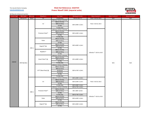
Ar-Mix Tri-Mix (He) 90% He 7.5% Ar 2.5% CO₂ 98% Ar 2% CO₂ 98% Ar 2% O₂
100 to 625 in/min
75 to 500 in/min
75 to 495 in/min
75 to 780 in/min
75 to 760 in/min
100 to 510 in/min
90 to 225 in/min
Wave Control 1 Pinch -10.0 to 10.0 UltimArc® -10.0 to 10.0 Pinch -10.0 to 10.0 UltimArc® -10.0 to 10.0 UltimArc® -10.0 to 10.0 Pinch -10.0 to 10.0 UltimArc® -10.0 to 10.0 Pinch -10.0 to 10.0 UltimArc® -10.0 to 10.0 Pinch -10.0 to 10.0 UltimArc® -10.0 to 10.0 UltimArc® -10.0 to 10.0
100 to 600 in/min
100 to 645 in/min 100 to 625 in/min 100 to 645 in/min 90 to 250 in/min 125 to 700 in/min 150 to 750 in/min 125 to 800 in/min
Wave Control 1 UltimArc® -10.0 to 10.0
- 1、下载文档前请自行甄别文档内容的完整性,平台不提供额外的编辑、内容补充、找答案等附加服务。
- 2、"仅部分预览"的文档,不可在线预览部分如存在完整性等问题,可反馈申请退款(可完整预览的文档不适用该条件!)。
- 3、如文档侵犯您的权益,请联系客服反馈,我们会尽快为您处理(人工客服工作时间:9:00-18:30)。
___________________________________________________________________________________________________ 故 障 排 除…………………………………………………………………………………………………………………E部分
A-1
安装
A-1
技术参数 TIG 375(K2623-1 出口-50/60Hz)
1111111111111111111111111111111111111111111111 额定单相输入 111111111111111111111111111111111111111111111
暂载率-应用
电压 ±10%
暂载率………………………………………………………………………………………………………………….B-1 推荐的工艺及设备…………………………………………………………………………………………………….B-2 控制和设置……………………………………………………………………………………………………...B-3至B-6 内部设置控制………………………………………………………………………………………………………….B-7 手工焊焊接功能……………………………………………………………………………………………………….B-7 TIG焊接功能…………………………………………………………………………………………………………..B-7
• 领导世界焊接和切割产品的先驱 • • 子公司和经销商提供的销售和服务遍布世界 • 美国俄亥俄州克里夫兰 44117-1199 电话:1.216.481.8100 传真:1.216.486.1751 网站:
vi
总目录
vi
_______________________________________________________________________________________________页数 安装……………………………………………………………………………………………………………………….….. A 部分 技术参数……………………………………………………………………………………………………………..…. A-1,A-2 安全守则………………………………………… ……… …… ……… ……… ……… ……… ……… ……… ……… ………... A-3
所适用的机型编号:11163
PRECISION TIG 375
请用户安全使用设备 林 肯 电气 公司 在设 计和 制造 焊接 和切 割 设备 永远 将 设备的安全性置于首位。用户的正确安装乃至谨慎操 作能增强其安全性。未经阅 读此手册及所包含的安全 事项,请勿安装 、操作或修理该设备。更为重要的是, 先思后行,谨慎操作。
最大电流-带功率因数电容
40% 交流/直流 焊条/平衡 TIG 8/68/62
60% 交流/直流 焊条/平衡 TIG 非平衡(70%熔深#)交流 TIG
220-230/ 380-400/415
110/64/59 97/56/52
100% 交流/直流 焊条/平衡 TIG 非平衡(70%熔深#)交流 TIG
___________________________________________________________________________________________________ 维 护 ……………………………………………………………………………………………………………………….D部分 安全守则…………………………………………………………………………………………………………………...D-1 日常和定期维护…………………………………………………………………………………………………………...D-1 过载保护…………………………………………………………………………………………………………………...D-1
___________________________________________________________________________________________________ 部 件 清 单…………………………………………………………………………………………………………………..P543
___________________________________________________________________________________________________ 操 作 ……………………………………………………… ……… ……… ……… ……… ……… ……… ……… ……… ……… ……… ……… ……… ……… ……… ……… ….. B部分 安全守则…………………………………………………………………………………………………………………...B-1 产品描述……………………………………………………………………………………………………………….......B-1 管道加热…………………………………………………………………………………………………………………...B-1
选择正确的安放地点………………………………………………………………………………………………….A-3 打磨…………………………………………………………………………………………………………………….A-3 堆放…………………………………………………………………………………………………………………….A-3 底盘的升降和移动…………………………………………………………………………………………………….A-3 放置……………………………………………………………………………………………………………...….….A-3 环境等级……………………………………………………………………………………………………….………A-3 焊机接地和高频干扰的保护………………………………………………………………………………………A-3,A-4 输入和地线连接…………………………………………………………………………………………………………..A-4 输出电缆,连接和限制…………………………………………………………………………………………………..A-5 工件电缆连接…………………………………………………………………………………………………………A-5 手工焊焊钳电缆连接…………………………………………………………………………………………………A-5 TIG焊枪连接………………………………………………………………………………………………………….A-6 辅助电源连接………………………………………………………………………………………………………....A-7 远程控制(可选)……………………………………………………………………………………………………A-7 机器人接口连接………………………………………………………………………………………………..A-7,A-8
___________________________________________________________________________________________________ 附 件 部 分………………………………………………………………………………………………………………....C部分 可选设备…………………………………………………………………………………………………………………...C-1
2步触发模式………………………………………………………………………………………………………...B-8 4步触发模式………………………………………………………………………………………………………...B-9 TIG焊接周期图………………………………………………………………………………………………………B-10 TIG焊电流调节器安装指南………………………………………………………………………………….B-10,B11 使用TIG焊电流调节器焊接…………………………………………………………………………………………B-12
惺 惺 惺 惺惜惺惺惺惺惜惺惺惺惺惜惺惺惺惺惜惺惺惺惺惜惺惺惺惺 惜惺惺信息 惺惺惜惺惺惺惺惜惺惺惺惺惜惺惺惺惺惜惺惺惺惺惜惺惺惺惺相惜惜惺惺惺惺惜惺惺惺惺惜惺惺惺惺惜惺惺惺惺惜惺 惺惺惺惜惺惺
惺惺惜惺惺惺惺惜惺惺惺惺惜惺惺惺惺惜惺惺惺惺惜惺惺惺惺惜惺惺信息惺惺惜惺惺惺惺惜惺惺惺惺惜惺惺惺惺惜惺惺惺惺惜惺惺惺惺惜惺惺信息惺惺惜惺惺惺惺惜惺惺惺惺惜惺惺惺惺惜惺惺惺惺惜惺惺惺惺惜惺惺信息惺惺惜惺惺惺惺惜惺惺惺惺惜惺惺惺惺惜惺惺惺惺惜惺惺惺惺惜惺惺信息惺惺惜惺惺惺惺惜惺惺惺惺惜惺惺惺惺惜惺惺惺惺惜惺惺惺惺惜惺惺信息惺惺惜惺惺惺惺惜惺惺惺惺惜惺惺惺惺惜惺惺惺惺惜惺惺惺惺惜惺惺信息 惺惜惺惺惺惺惜惺惺惺惺惜惺惺
___________________________________________________________________________________________________ 图 表 ………………………………………………………………………………………………………………………F部分 接线图……………………………………………………………………………………………………………….F-1,F-2 外形尺寸图…………………………………………………………………………………………………………F-3, F-4
IM936 2007 年 4 月
惺惺惜惺惺惺惺惜惺惺惺惺惜惺惺惺惺惜惺惺信息 惺惺惜惺惺惺惺惜惺惺惺惺惜惺惺惺惺惜惺惺惺惺惜惺惺惺惺相惜惜惺惺惺惺惜惺惺惺惺惜惺惺惺惺惜惺惺惺惺惜惺惺惺惺惜惺惺
操作手册惺
惺惜惺惺惺惺惜惺惺惺惺惜惺惺惺惺惜惺惺惺惺惜惺惺
惺惺惜惺惺惺惺惜惺惺惺惺惜惺惺惺惺惜惺惺惺惺惜惺惺惺惺惜惺惺
安全守则……………………………………………………………………………………………………………….…E-1 如何使用故障排除向导……………………………………………………………………………………………….…E-1 故障排除……………………………………………………………………………………………………………E-2至E-7