HP8920A综合测试仪使用说明
HP8920A综合测试仪使用说明

HP8920A综合测试仪使用说明HP8920A/B综合测试仪使用方法一、测试线的连接MAX PWR 60W——仪器射频信号输入输出(注意观察标注的最大功率值,可能有些仪器只能测试5W或者10W的功率)。
接被测试机器的天线头。
(此处不能接错!200mw的那个头不要输入大功率,否则,会损坏仪器!)AUDIO IN (HI)——音频信号输入(接对讲机外接耳机插孔,输入信号后仪器显示相应指标)。
AUDIO OUT——音频信号输出(接对讲机外接话咪插孔,仪器里面模拟出来的音频信号经过话咪插孔进入到对讲机里面进行调制,然后通过仪器显示相关指标)。
其它部分按钮说明:VOLUME:调节仪器蜂鸣器声音大小。
SQUELCH:旋钮上的色点一般调节在中心位置合适,不然,有噪声。
二、测试1、发射测试(检测机器时,一般先测发射,因为发射部分的一些指标不良,会影响到接收):按仪器面板上的“TX”按键,进入发射指标检测界面。
连接好对讲机各测试线并打开电源,按下对讲机的PTT按键,发射时,主要看仪器屏幕上的三个指标:Tx Frequency :频率误差(实际发射出来的频率值和该信道标称频率的差值,一般±500Hz即可。
Tx Power:功率大小FM Deviation:最大频偏(一般在4KHz左右,加亚音频之后,会高0.7KHz。
该指标影响对讲机的送话)。
在发射状态下,把仪器的滤波器调小:即把“Filter 1”选择到“<20Hz”,再把“Filter 2”选择到“300Hz”,即可以在“FM Deviation”这一栏直接查看到该信道所加的模拟亚音频数值。
2、接收测试:按仪器面板上的“RX”按键,在该界面,要设置以下参数:转动面板上的那个大的旋钮,让光标停留在“RF Gen Freq”处,直接按数字键和单位按键,即输入要测试对讲机的接收频率(如458.825MHz),然后,再把光标移到“Amplitude”这一项,分别输入1mv和0.25uv两种场强参数(看你自己的习惯,也可以用“-DBm”的单位),以检测机器的失真度和灵敏度。
安捷伦8960实用简易操作说明
安捷伦8960实用简易操作说明安捷仑8960综合测试仪是GSM和CDMA手机测试常见的测试仪器,现把在生产过程常用的设置和调试在此说明,以便大家需要时参考1.如何将自动测试转换到手动测试?答:按面板右上方LOCAL键,进入本地设置状态即可(注:自动测试是指当仪器连接了电脑所有测试过程由电脑软件控制;手动测试即人工手动直接对仪器进行选择设置和测试。
)2.如何查看8960仪器的当前GPIB地址?答:1.按SYSTEM CONFIG键,进入系统设置界面,即可看到GPIB 地址,如:GPIB Address:20 3. 如何知道8960仪器当前的测试类型CDMA还是GSM?如何转换?答:1.按SYSTEM CONFIG键,进入系统设置界面,即可看到,如:Application:GSM/GPRS Mobile Test目前产线常用的有两种,(1)G网手机,采用GSM/GPRS Mobile Test(2)C网手机,采用CDMA2000 Mobile TestGSM手机校准时需把C网换成G网,否则不能校准,转换方法如下:先按按面板右上方LOCAL键,再Application Selection进入子画面,按Application Switch ,进入测试类型选项,通过旋钮选择GSM/GPRS Mobile Test或CDMA2000 Mobile Test,按下旋钮键确定,再选择YES 按下旋钮键确定,仪器将执行自动重启进入选定测试类项。
4.如何修改8960仪器的线损值?答:按SYSTEM CONFIG键,进入系统设置界面,按RF IN/OUT Amptd offset进入子画面,按IN/OUT Amptd offset setup,旋钮选择对应频段,按下旋钮键,进入线损值修改,如-10 dB。
(线损值理论上应该通过测试来定,但实际应用中直接输入经验值有8,10,12dB,使OK手机测试功率在33±3dB之内即可.5.如何用8960测试手机发射功率?答:在待机界面,按Mesutement Selection 进入弹出窗口,用旋钮选择功率***POWER 项,注意:GSM900M频段测试功率等级有5——15级, GSM1800M频段测试功率等级有0—15级,GSM900测试信道:1—124(中间信道62);GSM1800测试信道: 512—885(中间信道698),通话测试时:900M功率等级选最大5,信道选62,功率标准为33±3dB;1800M功率等级选最大0,信道选698,功率标准为33±3dB6.GSM手机接收灵敏度测试用手机建立一个呼叫连接,按下Measurement selection键(测试项目选择),选择测量项GSM Bit Error(误码),按下F7(BCH),再按F7调节Cell Power(信元功率),当Bit Error(误码)不超过2.4%时,Cell Power的值即为所测手机的接收灵敏度,国标为-102 dBm。
AT9220系列综合安规测试仪用户手册

Rev.A 2.0固件说明:适用于主程序Rev.A 2.0及以上的版本AT9220系列综合安规测试仪ACW额定输出: 5kV / 20mADCW额定输出: 6kV / 10mAIR额定输出:1kV / 10GΩ直流快速放电、触电保护和电弧侦测功能999.9秒内任意设定的电压上升时间、测试时间、下降时间可存储、编辑10组测试组,每组16步HANDLER ( PLC ) 接口RS-232C接口& % 安柏®是常州安柏精密仪器有限公司的商标或注册商标。
安全须知当你发现有以下不正常情形发生,请立即终止操作并断开电源线。
立刻与安柏科技销售部联系维修。
否则将会引起火灾或对操作者有潜在的触电危险。
●仪器操作异常。
●操作中仪器产生反常噪音、异味、烟或闪光。
●操作过程中,仪器产生高温或电击。
●电源线、电源开关或电源插座损坏。
●杂质或液体流入仪器。
安全信息为避免可能的电击和人身安全,请遵循以下指南进行操作。
免责声明用户在开始使用仪器前请仔细阅读以下安全信息,对于用户由于未遵守下列条款而造成的人身安全和财产损失,安柏科技将不承担任何责任。
仪器接地为防止电击危险,请连接好电源地线。
不可在爆炸性气体环境使用仪器不可在易燃易爆气体、蒸汽或多灰尘的环境下使用仪器。
在此类环境使用任何电子设备,都是对人身安全的冒险。
不可打开仪器外壳非专业维护人员不可打开仪器外壳,以试图维修仪器。
仪器在关机后一段时间内仍存在未释放干净的电荷,这可能对人身造成电击危险。
不可在有强烈磁场或者电场的地方使用该仪器,电磁脉冲会引起仪器故障产生火灾。
在强烈磁场环境使用该仪器不要如果在本仪器的附近使用这些设备,被测件失效击穿产生的噪声也许会影响这些设备。
在敏感的测试设备和超过3kV的测试电压,测试线间的电场会电离空气产生电晕,在测试线之间产生大量接受设备附近使用该仪器的射频带宽的干扰。
为了减少这种影响,确保测试线之间的距离足够远。
另外,保持测试线远离导电表面(特别是尖鋭的金属末端)。
Keysight M8920A PXIe 无线电测试设备说明书
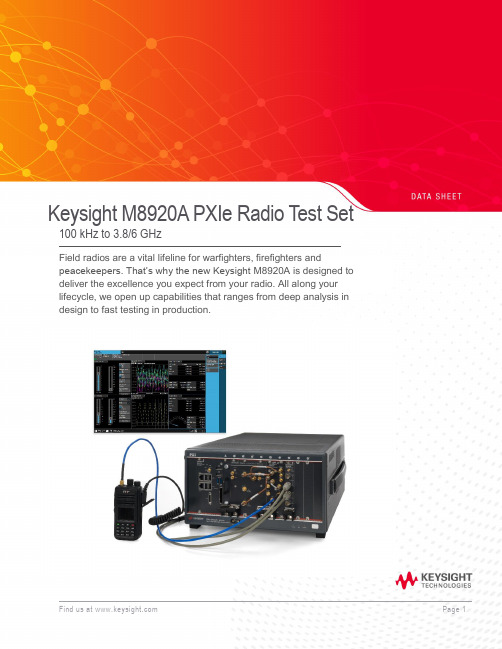
Keysight M8920A PXIe Radio Test Set 100 kHz to 3.8/6 GHzField radios are a vital lifeline for warfighters, firefighters andpeacekeepers. That’s why the new Keysight M8920A is designed to deliver the excellence you expect from your radio. All along your lifecycle, we open up capabilities that ranges from deep analysis in design to fast testing in production.Table of ContentsAccelerate MilCom and public safety radio manufacturing (3)Applications (3)Technical Specifications (4)Definitions and conditions (4)RF Analyzer Technical Specifications and Characteristics (5)RF Analyzer Technical Specifications and Characteristics (Continued) (6)RF Generator Technical Specifications and Characteristics (7)RF Generator Technical Specifications and Characteristics (Continued) (8)Audio Module Technical Specifications and Characteristics (8)Audio Module RX Audio Filters (9)Radio Test Application Specifications (9)N9093EM0E basic analog demodulation measurement application key specifications (9)N9093EM1E basic digital demodulation measurement application key specifications (9)Connectivity Test Application Specifications (10)WLAN 802.11ac (10)LTE-FDD/TDD (10)Bluetooth (10)Front Panel M9470A RF Interface Module Connections (10)General Specifications (11)Related Literature (12)Additional Information (12)Accelerate MilCom and public safety radio manufacturingDigital 2-way radios being developed for MilCom and the public safety radio market bring new testing challenges and hurdles to overcome for manufacturers and depot testing. Radio technologies are requiring wider bandwidths, higher frequencies, and multiple radio format capabilities.Product descriptionKeysight’s M8920A PXIe Radio Test Set supports many formats by combining PXI hardware with application-specific software in a single flexible and scalable chassis, providing broad multi-format coverage for next-generation radio testing.With Keysight’s new Radio Test Measurement Application (N9093), you can access and control multiple instruments on one screen while viewing a variety of critical measurements at the same time. Keysight can help deliver the operational excellence you expect from your radio.Applications−Cover all necessary analog AM and FM modulation test requirements.−Test APCO P1/P2, TETRA1, DMR, dPMR, ARIB, and custom modulation formats.−Test commercial connectivity formats including WLAN, LTE, Bluetooth®, etc.−All measurements can be performed with one click of a button.−Test analog Avionics Radios, and your Avionics Databus with optional Databus modulesM8920A PXIe Radio Test SetTechnical SpecificationsDefinitions and conditionsSpecifications describe the warranted performance of calibrated instruments. Data represented in this document are specifications under the following conditions unless otherwise noted.−Specifications are valid from 40° to 65 °C for individual module temperature, as reported by the module, and 20° to 35 °C for environment temperature unless otherwise noted −Calibrated instrument has been stored for a minimum of 2 hours within the allowed operating range−If instrument has previously been stored at a temperature range inside the allowed storage range, but outside the allowed operating range, instrument must have been stored for a minimum of 2hours within the allowed operating range before turn-on−30-minute warm-up time−Calibration cycle maintained−The RF, IF, and Source Alignments have been run within the previous 7 days−An ALL Alignment has been run within the previous 8 hours−If the temperature has changed more than 5 °C from the previous ALL AlignmentTypical describes additional product performance information that is not covered by the product warranty. It is performance beyond specifications that 80% of the units exhibit with a 95% confidence level. This data, shown in italics, does not include measurement uncertainty, and is valid only at room temperature (approximately 25 °C) after alignment within the stated alignment time and temperature limits.Nominal values indicate expected performance or describe product performance that is useful in the application of the product but are not covered by the product warranty.Recommended best practices in use−Use slot blockers and EMC filler panels in empty module slots to ensure proper operating temperatures. Keysight chassis and slot blockers optimize module temperature performance and reliability of test.−Set chassis fan to high at environmental temperatures above 45 °C.RF Analyzer Technical Specifications and Characteristics1.Instantaneous b andwidth (1 d B b andwidth) a vailable a round a c enter frequency o ver w hich t he i nput s ignal c an b e d igitized f or further a nalysis o rprocessing in the time, frequency or modulation domain.2.Calibration a ccuracy d epends o n h ow a ccurately t he f requency s tandard w as a djusted t o 10 M Hz. I f t he a djustment p rocedure i s f ollowed, t he c alibration accuracyis given by the specification. Achievable Initial Calibration Accuracy.3.The 3-dB cutoff frequency can be selected for the User-defined audio filters.RF Analyzer Technical Specifications and Characteristics (Continued)1.T/R port high power attenuation OFF2.Except at 100 MHz, 5 GHz, and 5.5 GHzRF Generator Technical Specifications and Characteristics1.Calibration a ccuracy d epends o n h ow a ccurately t he f requency s tandard w as a djusted t o 10 M Hz. I f t he a djustment p rocedure i s f ollowed, t he c alibrationa ccuracy is given by the specification. Achievable Initial Calibration Accuracy.2. Specifications apply when input port is set to Antenna InRF Generator Technical Specifications and Characteristics (Continued)Audio Module Technical Specifications and CharacteristicsAudio Module RX Audio FiltersRadio Test Application SpecificationsN9093EM0E basic analog demodulation measurement application key specificationsN9093EM1E basic digital demodulation measurement application key specifications1. The 3 dB cutoff frequency can be selected for the User-defined audio filters.Connectivity Test Application SpecificationsWLAN 802.11acLTE-FDD/TDDBluetoothFront Panel M9470A RF Interface Module ConnectionsGeneral SpecificationsFind us at Page 11PPFind us at Page 12Learn more at: For more information on Keysight Technologies’ products, applications or services , please contact your local Keysight office. The complete list is available at: /find/contactusThis information is subject to change without notice. © Keysight Technologies, 2018, Published in USA, Month July 11, 2019, 5992-2802ENRelated LiteratureFor more detailed product and specification information refer to the following literature and web pages: Publication titlePublication number M8920A PXIe Radio Test Set Technical Overview 5992-2821EN M8920A PXIe Radio Test Set Configuration Guide 5992-2800EN M8920A PXIe Radio Test Set Getting Started Guide M8920-90001 M9470A PXIe 50W Interface Module Data Sheet 5992-3140EN M9421A VXT PXIe Vector Transceiver Data Sheet 5992-1646EN M9260A PXIe Audio Analyzer Data Sheet 5992-1918EN PXIe Chassis Spec GuideM9019-90015 PC Tested Configurations with PXIe Chassis Technical Overview 5990-7632EN M9037A PXIe Embedded Controller Spec Guide M9037-90015 Interface Modules and Adapters for PXIe Systems5992-0377EN M924XA InfiniiVision PXIe Modular Oscilloscopes Data Sheet 5992-2003EN 6.5 Digit PXI Digital Multimeter Data Sheet 5992-2757EN PXIe Vector Network Analyzer Configuration Guide 5991-4885EN PXI Avionics Bus Interface Cards Configuration Guide 5992-2448EN 89600 VSA Software Configuration Guide5990-6386ENAdditional InformationProduct webpages:/find/M8920A /find/N9093 /find/PXIX-Series measurement applications: /find/X-Series_AppsSignal Studio Software:/find/signalstudio89600 VSA Software:/find/89600Bluetooth and the Bluetooth logos are trademarks owned byBluetooth SIG, Inc., U.S.A. and licensed to Keysight Technologies, Inc。
8960综合测试仪中文说明

日本
$JLOHQW 7HFKQRORJLHV -DSDQ /WG 0HDVXUHPHQW $VVLVWDQFH &HQWHU 7DNDNXUD&KR +DFKLRML6KL 7RN\R -DSDQ 日本 电话 传真
(??FKDSWHUV?WLWOHSDJHIP
澳大利亚 新西兰
$JLOHQW 7HFKQRORJLHV $XVWUDOLD 3W\ /WG %XUZRRG +LJKZD\ )RUHVW +LOO 9LFWRULD 澳大利亚 新西兰 电话 电话 传真 传真 电话 传真 香港
拉丁美洲
$JLOHQW 7HFKQRORJLHV /DWLQ $PHULFD 5HJLRQ +HDGTXDUWHUV %OXH /DJRRQ 'ULYH 6XLWH 0LDPL )ORULGD 86 $ 美国 电话 传真
$JLOHQW 产品编号 印刷日期
年 月 年
版权所有 Agilent Technologies
ZZZDJLOHQWFRPILQGVXSSRUW
印刷日期
下文列出了本手册的所有版本和更新以及其创建日期 年 月 年 月 年 月
$JLOHQW 7HFKQRORJLHV 系列 无线通讯测试仪
手动操作
入门指南
$036 移动台测试仪应用程序 ($ 修订版 $ FGPD 移动台测试仪应用程序 (% 修订版 % *356 移动台测试仪应用程序 ($ 修订版 $ *60 移动台测试仪应用程序 ($ 修订版 $ *60B$036B*356 快速切换 ($ 修订版 $
Fluke 8920A、8921A和8922A多功能电压计说明书

FLUKE 8922A8920A, 8921A & 8922AAutorangingFluke's autoranging feature allows you to carry out your testing without having to change ranges manually. A range can be placed on HOLD or manually stepped up to a higher range. On HOLD, the meter will remain in a given range regardless of changes in input levels. On STEP UP, the meter will increase ranges step-by-step until the switch is released. Peaking/Dipping MeterIn addition to an accurate digital display, all Fluke Voltmeters in the 8920-Series feature an analog meter for peak and null voltage adjustments. The meter indicates O to 100 percent full scale in each range.Linear Analog OutputModels 8920A and 8922A are equipped with a rear panel output for driving X-Y or st d p chart recorders, delivering voltages proportional to the display count. A 2-volt level equals 2000 counts, a 1-volt level equals 1000 counts, etc. This feature is not available on Model 8921A. AccuracyFluke Digital Voltmeters avoid the possibilities for error so common in analog meters. The digital displays eliminate the likelihood of misreading the meter due to viewing angle problems of parallax common with analog meters. Also, the accuracy of 8920-Series Voltmeters is specified as a percent of reading rather than as percent of full scale.Percent of reading accuracy does not degrade for measurements at the low end of a scale. Front panel switching offers a choice of readings in dB or volts.Technical SpecificationsThe a ccuracy s pecifications b elow apply from 9% to 100% of full scale and from 18°C to 28°C for 90 days. For six-month specifications multiply figures by 1.5.AC Accuracy: ± % of voltage reading or ±dB (8920A/8921 A)Range 2Hz 10 H z 20Hz 50Hz 10 kHz 700V200V1%or 0.5%or 20V 0.15dB 0.1 dB 2V Not200mV Speci-5%orlied 0.5dB 2%or 1%or 20 m V 0.25 d B 0.15dB3%or 2%or 2mV0.35dB 0.25dBAC Accuracy: ± % of voltage reading or ±dB(8922A)Range 2Hz 10 H z 20Hz 50Hz 10 k HzFILTER IN I700V200V 1%or•0.15 d B 1%or 0.5%or20V 0.15 d B 0.1 d B2V 5%or200 mV 3%or• 0.5dB0.35dB2%or•0.25dB 2%or 1%or20 mV 0.25 d B 0.15 d B5%or0.5dB5%or• 5%or 3%or 2%or I2 mv0.5 d B .. 0.5dB 0.35 d B 0.25dB• Valid when AC + DC DAMPING is selected andinput has no de components.••Below 2 mV add number of digits (N) to ±5% voltage readings, where N = 5 + mV input. Or, for dBreadings. add N to ±0.5 dB, where N = 0.5 + (mVinput)2AC+DC Accuracy: Add to AC accuracy specifications (above) ±10 digits or ±0.5 dB above 2mV, or ±100 digits or ±5.0 dB below 2 mV. Forde only, add above digits to 50 Hz to 10 kHzspecificationsFunctions: True RMS measurements only. ACor AC+ DC (8920A and 8921 A); AC or AC+ DCwith damping (8922A)Maximum Input: 700V rms or 1 O OOV peak, not toexceed a volt-hertz product of 1 x 10⁸ on anyrangeMaximum Common Mode Voltage8920A and 8922A: 400 mV rms or 600 mVpeak8921A: 500V rms or 700V peakAC Common Mode Rejection: �60 dB at 50 and60 Hz with 1000 unbalanceDC Common Mode Rejection: �100 dB, 1000unbalanceCrest Factor: 7 at full scale, increasing downscale by 7 times the voltage range divided by thevoltage input. Degrades below 10 Hz, annunciated when capability exceeded (8922A only)Input Impedance: 10 MO shunted by <30 pF200kHz 1 MHz 2MHz 10 M Hz 20MHzNot Specified0.7%or0.15 d B3% o r0.35 d B 5%or0.5dB2%or0.25dB 4%or0.4dB I3%or0.35dB200kHz 1 MHz 2MHz 11 MHzFILTER OUTNot Specified0.7%or0.15 d B3%or0.35 d B2%or 5%or0.25 d B 0.5dB4% o r0.4 d BVoltage R11nges: 2 mV, 20 mV, 200 mV, 2V, 20V,200V, 700VRanging: Autoranging with HOLD to defeat a�to•ranging and STEP UP for manual ranging.Ranges up at 2000 counts and ranges down at180 countsDecibel Ranges: In the autorange mode, theinstrument appears as though it has a singlerange spanning 131 dBdBm Reference: Twelve user-selectable impedances are provided to reference a O dBm, 1mW level (500,750,930, 1100, 1240, 1350,1500, 3000, 6000, 9000, 10000, and 12000)(dBV = 10000)Relative dB Reference: A voltage input presentwhen this button is pushed is held as "O dB"reference point. Subsequent readings indicate±deviations from this pointVoltage Resolution: 0.05% of ranges (3½ digits)Decibel Resolution: O.Q1 dB (4½ digits)Typical-3 dB Points: 40 MHz on 20 mV thru 20Vranges and 4 MHz on 2 mV range (8920A/8921 A); 22 MHz on 2 mV to 20V ranges (8922A)Low Pass Filter: Approximately 200 kHz -3 dBpoint, on 8922A onlyReading Rate: 2.5/s or 1 /s with ac + de withdamping (8922A)Autorange Rate: <950 ms or <3.5s with ac + dewith damping (8922A)Response Time: (To rated accuracy) <1.6s or<7s with ac + de with damping (8922A)Readout: Panel-select able for volts or dB,auto•matic decimal point location: analog peaking/dipping meter. " V .. "V .. "dB,,LED Annunciators: Indicate m , ,"REL REF," and "2 MHz MAX" for 2 mV range(8920A and 8921A) and "UNCAL" when crestfactor limitation exceeded (8922A)Overrange: Flashes maximum reading for thatrangeUnderrange: Flashes decimalLinear Analog Output: (8920A and 8922A only)Linear output of 2000 mV de for a 2000-countreadout; ±1.0% relative to display; essentiallyoo output into a �10 kO load; non-isolated, withoutput common same as input common。
HP HP HP C综测详细操作

HP8920HP8921HP8924C综测详细操作一、射频分析RF ANALYZER模式------------------------2二、接收机测试模式------------------------4三、音频分析------------------------6四、发射机测试------------------------9五、射频信号发生器------------------------12六、双工模式------------------------14七、频谱分析------------------------17八、示波器------------------------22专业对讲机方案提供商联创电子赖工整理泉州市南安大霞美南丰花园城QQ:27116723一、射频分析RF ANALYZER模式本屏为射频分析RF ANALYZER模式。
用于测试发射机的各种发射参数。
说明如下:一、Tune Mode调谐模式。
可自动Auto和手动Manual。
a)当Tune Mode调谐模式设置为手动Manual时,Tx Frequency以误差形式显示,并显示为TX Freq Error。
b)当Tune Mode调谐模式设置为自动Auto时,Tx Frequency以频率显示。
二、Tune Freq调谐频率。
三、TX Power发射功率。
四、Input Port射频输入口选项。
a)RF In表示射频信号从射频输入/输出口RF IN/OUT进。
通常大功率信号从此口进。
b)Ant表示射频信号从天线输入口ANT IN进。
弱小信号一般从此口进。
五、Input Atten输入衰减。
可选自动Auto和保持Hold。
a)当选自动时,机器根据输入信号的大小,自动选择输入衰减值0dB,20dB或40dB。
b)当选择保持时,衰减值保持不变,可手动选择衰减值。
六、Sensitivity天线输入口ANT IN灵敏度选择。
a)Normal表示正常灵敏度。
综合测试仪HP8920/21操作快速入门

如何使用频谱分析仪观测信号
在“To Screen”下选择SPEC ANL进入 SPECTRUM ANALYZER 在“Controls”下选择相应的输入端口RF In/Ant 在“Center Freq”下设置待测的中心频率 根据带测的信号功率在“Ref Level”下设 置合适的参考功率 在“Span”下设置水平显示范围
如何建立一个带信令的单音调制信号
建立一个单音调制信号 在“To Screen”下选择“ENCODER”设置 好要求的信令(在信令那一节会详细讲 述) 按下按键“PREV”回到RX TEST界面 在“AFGen2”下选择Send/Stop; 即可实现带信令的单音调制信号的发生与 关闭
如何建立一个两音调制信号
如何选择示波器输入
在“To Screen”下选择SCOPE可进入示波器界面 选择示波器输入方式需在“To Screen”下选择AF ANL进入AF Analyzer 在“AF Anl In”下选择正确的音频输入方式 在面板上按下按键PREV重新进入示波器界面 常用两种方式: FM Demod:调频解调音频输入 Audio In:音频端口输入
如何测量载波频率及频率误差
在“Tune Mode”下选择Auto 连接端口后发射测量信号 在“TX Frequency”下将显示载波信号的频 率 在“Tune Mode”下选择Manual 在“Tune Freq”下设定解调频率 在“TX Freq Error”将显示频率误差
如何选择射频输入端口
RX Test And RF Generator
如何建立一个单音调制信号 如何建立一个带信令的单音调制信号 如何建立一个两音调制信号 如何选择射频输出端口
- 1、下载文档前请自行甄别文档内容的完整性,平台不提供额外的编辑、内容补充、找答案等附加服务。
- 2、"仅部分预览"的文档,不可在线预览部分如存在完整性等问题,可反馈申请退款(可完整预览的文档不适用该条件!)。
- 3、如文档侵犯您的权益,请联系客服反馈,我们会尽快为您处理(人工客服工作时间:9:00-18:30)。
HP8920A/B综合测试仪使用方法
一、测试线的连接
MAX PWR 60W——仪器射频信号输入输出(注意观察标注的最大功率值,可能有些仪器只能测试5W或者10W的功率)。
接被测试机器的天线头。
(此处不能接错!200mw的那个头不要输入大功率,否则,会损坏仪器!)
AUDIO IN (HI)——音频信号输入(接对讲机外接耳机插孔,输入信号后仪器显示相应指标)。
AUDIO OUT——音频信号输出(接对讲机外接话咪插孔,仪器里面模拟出来的音频信号经过话咪插孔进入到对讲机里面进行调制,然后通过仪器显示相关指标)。
其它部分按钮说明:VOLUME:调节仪器蜂鸣器声音大小。
SQUELCH:旋钮上的色点一般调节在中心位置合适,不然,有噪声。
二、测试
1、发射测试(检测机器时,一般先测发射,因为发射部分的一些指标不良,会影响到
接收):按仪器面板上的“TX”按键,进入发射指标检测界面。
连接好对讲机各测
试线并打开电源,按下对讲机的PTT按键,发射时,主要看仪器屏幕上的三个指标:Tx Frequency :频率误差(实际发射出来的频率值和该信道标称频率的
差值,一般±500Hz即可。
Tx Power:功率大小
FM Deviation:最大频偏(一般在4KHz左右,加亚音频之后,会高
0.7KHz。
该指标影响对讲机的送话)。
在发射状态下,把仪器的滤波器调小:即把“Filter 1”选择到“<20Hz”,再把“Filter 2”选择到“300Hz”,即可以在“FM Deviation”这一栏直接查看到该
信道所加的模拟亚音频数值。
2、接收测试:按仪器面板上的“RX”按键,在该界面,要设置以下参数:转动面板
上的那个大的旋钮,让光标停留在“RF Gen Freq”处,直接按数字键和单位按键,即输入要测试对讲机的接收频率(如458.825MHz),然后,再把光标移到“Amplitude”
这一项,分别输入1mv和0.25uv两种场强参数(看你自己的习惯,也可以用“-
DBm”的单位),以检测机器的失真度和灵敏度。
设置好后,如果机器正常,喇叭
会发出声音,用耳机测试线插入耳机插座,仪器里面则可以显示出接收机的参数:“SINAD”表示对讲机接收的失真度(场强为1mv时)和灵敏度(信号场强为0.25uv时,这个参数一般大于12dB为正常(越大越好),失真度一般在30dB左右就可以(当音量调为1V以下时看这个指标,越大越好)。
“AC Level”显示接收声音的大小,受音量开关控制,调到最大音量一般在3V左右。
三、亚音/数字亚音频的设置:当机器加了亚音频时,需要在仪器里面设置相应参
数,对讲机才可以正常解调出音频参数,然后喇叭发出声音。
在RX接收测试界面,将光标移到“AF Gen2 Frea”,把该参数改成实际的亚音频率(如67Hz),再把光标移到下面“AF Gen2 TO”的“Off”一项,改为500Hz(固定的参数)即可。
这里只能测试模拟亚音,如果要测试数字亚音的解码功能,则需在另外一个界面进行设置。
请见后面的描述。
1、数字亚音编码的设置:在RX接收测试界面,把接收频率和场强设置好,然后,把
光标移到仪器右边的“To Screen”,选择“ENCODER”——右边“Mode”选项,
选择“CDCSS”——在屏幕的左上角“Code”输入你要测试的数字亚音(如074)
——“Send Mode”选择“cont”——“AF Gen To”下的“FM”输入“500Hz”(固
定的数据)——“Polarity”选择“Norm”或者“Invert”(即测试亚音的正反向)。
其它选项默认即可,此时,如果接收机正常,则可解调出数字亚音,喇叭发出声音。
2、数字亚音解码的设置(即在不知道对讲机该信道数字亚音的情况下,如何测试出它
的参数):在TX发射测试界面,把光标移到仪器右边的“To Screen”,选择
“DECODER”——Arm Meas 下面选择到“cone”——“AF Anl In”这一项选择
到“FM Demod”——“In Put Level”输入“500Hz”。
这时候发射被测试机器,则
在左边的窗口从上至下会显示三排数字,第一排数字即为数字亚音。
如果显示不对
或者数字不稳定,则把“Polarity”选择成“Invert”。
3、示波器:把光标移到仪器右边的“To Screen”,选择“SCOPE”。
进入这个里面后,
象普通示波器一样调整个别参数,便于查看波形即可。
4、频谱仪:把光标移到仪器右边的“To Screen”,选择“SPEC ANL”。
进入到这个界
面后,主要设置好所测试参数的中心频点及带宽,便于查看频谱状况即可。
四、仪器界面的保存
当设置好一个界面后,以后有可能经常会用到这个界面,我们可以把这个界面存储起来,下次使用时,直接调出即可,不用每次都去设置。
步骤:在设置好的界面,按挨着屏幕的一个绿色存储按键“SHIFT”,然后再按上面一排按键中的“RECALL”,这时,结合中间的那个大旋钮,选择好便于记忆的字母或者数字(通过旋转中间的那个大旋钮选取字母,注意:每选取一个要点击一下旋钮。
如:TX-150、RX-SQ等),选择完毕后,移动光标到右边菜单最上面的“Done”确定即可。
下次要使用的这个界面,则按“RECALL”,通过旋转大旋钮让光标停留在设置的快捷菜单上,点击大旋钮确认即可。
如果要删除这个快捷菜单,让光标停留在这个菜单上,按两次“ON/OFF”按键即可删除。
以上介绍的属于HP8920A/B综合测试仪最基本的一些应用,这个仪器的功能比较多(可能有些功能需要选件卡的支持),对于一般的对讲机、车台的测试,掌握到以上的方法就可以了,若想要了解更多测试,可参考仪器光盘里面的说明书。