WU TE432q高精度关口电能表用户手册V1 2
三相无功功率监测仪表使用说明书

1概述1.1产品简介DTSD342(配置号为7Q)型三相无功功率监测仪表用于测量电网三相无功功率,它采用大屏幕LCD显示,可通过RS485进行数据采集,RS-485通信支持MODBUS-RTU和DL/T645双通信规约;具有开关量输入、输出功能。
本仪表广泛适用于变配电自动化系统、工业控制和工业自动化系统、能源管理系统和小区电力监控等场合。
1.2产品特点本仪表采用了高精度采样计量单元和高速MCU数据处理单元,可实现高精度宽范围准确计量和快速数据分析;采用段码式多行宽视角液晶显示屏,显示内容很丰富;液晶配备白色背光,可满足黑暗环境下查阅数据的要求;采用非易失存储器存储各类数据,可长时间保存数据且掉电不丢失;支持RS485通信端口和工业标准通信规约,组网便捷灵活;选配不同通信模块,可满足多种用户的不同接口需求。
2技术指标3功能介绍3.1参数测量功能本仪表可测量总和各分相无功功率。
3.2越限报警功能(1)仪表具备越限事件报警功能。
用户可从电压、电流、功率、功率因数和频率等参数中最多同时选择6个数据作为检测对象,对其设定高低限值和判断条件,当测量值越过设定的限值时报警。
仪表带有1路继电器输出,当报警参数配置为某继电器输出且该继电器为自动方式(非手动方式)时,越限报警信号就可通过该路继电器输出(继电器合闸)。
(2)仪表内部最多可同时设置6组越限报警参数。
各组越限报警参数的配置流程为:选择检测数据类别→设置检测数据阀值→设置判断条件→选择报警信号输出继电器。
①各类检测数据代码如下:(DL/T645代码为十进制数;Modbus-RTU代码为十六进制数)当检测数据代码为FF时表示该组越限报警功能关闭。
②检测数据阀值:检测数据是否越限的判断阀值。
不同的数据类型有不同的单位,如:电压—V;电流—A,有功—KW,无功—KV AR,视在—KV A,频率—Hz。
③判断条件:设置为0表示大于限额值报警;1表示小于限额值报警。
三相预付费复费率电能表用户使用手册8页word

预付费多费率电能表用户使用手册一、概述该电子式预付费复费率电能表(以下简称“仪表”)是根据居民实际用电状况所设计、制造。
它具有较高的准确度和可靠性。
本仪表采用先进的电能计量专用芯片,与成熟的复费率、预付费技术相结合设计而成,应用16位数字采样处理技术及SMT工艺制造的高新技术产品。
关键元器件选用国际知名品牌的长寿命器件,提高了产品的可靠性和使用寿命,数据显示采用大屏幕液晶,便于抄表。
该仪表能实现分时计量预付费,设定日抄表,掌上电脑编程及抄表等功能;可设置2个时区,3种费率,12个日时段;并具有红外和485通讯功能,可实现远距离抄表,通信规约可支持DL/T 645-2007《多功能电能表通信规约》,为用电自动化管理提供了必备的条件。
其性能指标符合GB/T 17215-2002《1级和2级静止式交流有功电度表》中对电子式有功电度表的技术要求,符合GB/T15284-2002《多费率电能表特殊要求》对复费率电能表的技术要求,并符合GB/T18460-2001《IC卡预付费售电系统》的各项技术要求。
二、主要功能预付费复费率电能表具有以下基本功能:3.1 分时有功正、反向电能计量,无功电量计量,可分为4种费率、12个时段、8个时区。
3.3 可通过掌上电脑进行红外通讯、完成编程设置和抄表。
3.4 可实现参数轮显,轮显的参数(不超过32项)和时间间隔可预先设置,参数轮显的顺序也可任意设定。
3.5 带光耦隔离有功无源脉冲输出接口,脉冲常数和电表常数相同。
3.6 记录12个月的有功总电量和分时电量,并可通过红外或485方式抄表。
3.7 具有编程禁止功能和数据清零功能。
3.8 支持部规约的缩位抄表。
3.9 具有先购电后用电,并在指定抄表日自动冻结每月的各费率用电量。
3.10可使用IC卡进行参数设置和抄表。
3.11采用一表一卡方式,IC卡内数据多重校验和加密,安全可靠。
3.12 每次购电能通过电卡进行双向传递数据。
3.13 能设置非工作营业时段和应急赊欠限量。
Agilent N432A Thermistor Power Meter 数据手册说明书

Agilent N432AThermistor Power MeterData SheetAgilent’s only power meter that supports thermistor mount with useful enhancements for metrology and calibration lab environments.Why Agilent’s Power Meters and Sensors?Reliable, high-performing solutionsEvery power meter and sensor from Agilent consistently delivers great results.A sure investment for many years to comeCode-compatibility between power meters reduces the need for re-coding. Notonly that, all Agilent power meters are backward-compatible with most legacypower sensors.One specific application: One right solutionAgilent offers a wide selection of power meters and sensors for practicallyall application needs—wireless communications, radar pulse measurements,component test, and more.Global network supportNo matter where you are, Agilent is committed to giving you the 24-hoursupport you need regarding our products, applications, or services.Agilent’s power meters have long beenrecognized as the industry standard forRF and microwave power measurements.We Listened to the Industry, Then Delivered a Better and Easier Replacement Solution for the Legacy 432A Analog Power MeterAs today’s power measurements become more complex, it is increas-ingly difficult to make reliable, accu-rate power measurements. For more than 40 years, you’ve depended on Agilent’s 432A analog power meter, used with temperature compensated thermistor sensors to provide high accuracy over a wide temperaturerange. LXI Class-C compliant N432AThe N432A is a single-channel, aver-age RF power measurement meter that supports thermistor sensors. The N432A has the capability to measure and display average power, RF bridge voltages (V RF0 and V RF1), compensation bridge voltages (V COMP0 and V COMP1), V 0, and V 1. It is also provided with a set of features such as zeroing and a built-in self-test.Developed using LXI technology, the N432A is an LXI Class-C compli-ant instrument.1 The N432A basic configuration consists of two key sections: bridge and meter logic. When a compatible thermistor sensor is connected to the N432A, the RF and compensation bridge circuits are formed in the bridge section. V RF , which is the voltage at the top of the RF bridge, is responsive to both input RF power and ambient temperature changes. On the other hand, V COMP , which is the voltage at the top of the compensation bridge, is responsive only to ambient temperature changes. The V RF and V COMP values are used in calculating the RF power. Meanwhile, the meter logic section processes V RF and V COMP to produce a meter current proportional to RF power.In general, the N432A is an easy-to-use instrument, especially with the availability of an integrated Web browser that provides a con-venient way to view and modify the instrument network configuration. Besides the LAN interface, the N432A also supports industry standard GPIB and USB interfaces for measurement automation.Today, the Agilent N432A digital thermistor power meter, loaded with enhancements, including a color digital display, and intuitive front panel interface will continue support your measurement needs with greater capability and expanded functionality. Best of all, you can get these extras at just a fraction of the price of the legacy 432A.1. LXI, an acronym for LAN eXtension for Instrumentation, is an instrument standard for devices that use the Ethernet (LAN) as their primarycommunication interface.High accuracy—no thermoelectric errorThe high accuracy ± (0.1% of reading + 0.5 μW) over a wide temperature range featured in the legacy 432A power meter is also included in the N432A, making it excellent for 1 mW transfer calibration (with 478A-H75/ H76*). Accuracy can be maintained on even the most sensitive range as the error due to thermoelectric effect is reduced to a negligible level.* 478-H75/H76 has a maximum SWR of1.05 at 50 MHz Sensor compatibilityThe N432A is compatible with the Agilent 478A and 8478B thermistor sensors. The following table lists the frequency range and operating resistance for these two sensors:478A0.01 to 10200478A Option H630.000001 to 1200478A Option H750.001 to 1200478A Option H760.001 to 12008478B0.01 to 18200For further information on the thermistor sensors, refer to the respective manuals.Take a Closer Look N432A front panel N432A back panelHigh-resolution color LCD display for easy viewing of test results Display key allows selection of the display format for the active window (single/split screen)Display key allows selection of the display mode (windowed, expanded, or full-screen) of numeric measurements Hard keys provide quick access to the most frequently used functions, such as System, Trigger, and Acquisition, etc.Channel sensor connectorArrow keys enable navigation of parameter entry screens, values selection, and entering of text Soft keys provide menu selection Numeric keypad for easy entry of numeric values Power reference of 1 mW (0 dBm)Ground connectorDC recorder outputs (DC voltage corresponds to the power level of the channel input)V RF and V COMP output terminals for calibrating the N432A and for precision power measurements Line power accepts voltage with automatic range selectionGo beyond GPRB with USB and LAN/LXI-C interfaceSpecifications and CharacteristicsSpecifications describe the instrument’s warranted performance and apply after a 30 minute warm-up.These specifications are valid over its operating/environmental range unless otherwise stated and after performing a zero and calibration procedure.Supplemental characteristics (shown in italics) are intended to provide additional information, useful in applying the instru-ment by giving typical (expected), but not warranted performance parameters. These characteristics are shown in italics or labeled as “typical”, “nominal” or “approximate”.Frequency range100 kHz to 18 GHz, sensor dependent Power range–30 to +10 dBm (1 μW to 10 mW), thermistor-sensor dependent Compatible power sensors• Agilent 478A thermistor sensor (100 kHz to 10 GHz, with option H63)• Agilent 8478B thermistor sensor (10 MHz to 18 GHz)Meter power accuracy Power absolute accuracy± (0.1% of reading + 0.5 μW)Meter voltage accuracy (1-year reference specifications) V RF and V COMP V 0 and V 1 23 °C ± 5 °C: ± (0.0035% + 50 μV) [reading + range] 23 °C ± 5 °C: ± (0.0040% + 25 μV) [reading + range]Bridge resistance100, 200, 300, or 400 Ω (user selectable)Display units Power Relative V RF , V COMP , V 0, and V 1 Bridge resistanceWatts (W) or dBm Percent (%) or dB VDC and mVDC Ohm Display resolution PowerDefault resolution Voltage Bridge resistance Selectable resolution of: 1.0, 0.1, 0.01 and 0.001 dB in logarithmic mode, or 1, 2, 3, and 4 significant digits in linear mode 0.01 dB in logarithmic mode or three digits in linear mode 6.5-digit resolution 6.5-digit resolutionAccessed by key entry Either hard keys, or soft key menu, and programmableZero Zeros the meter. (Power reference calibrator is switched off during zeroing)Frequency Entered frequency range is used to interpolate the calibration factors table. Frequency range from1 kHz to 999.9 GHzBridge resistance type Setting the bridge resistance, user-selectable Rmeasure (factory set) or Ruser (measured by user) Cal factor Sets the cal factor versus frequency for the calibration factor for power sensor. Range: 1.00% to150.00%, in 0.01% increments. Cal factor can be set from either CF table or single entry CF Relative Displays all successive measurements relative to the last displayed valueOffset Allows power measurements to be offset by –100 to +100 dB, settable in 0.001dB increments, tocompensate for external loss or gain. Offset table can be set from either CF table or single entryCFSave/recall Store up to 10 instrument states via the save/recall menuMeasurement averaging Selectable from 4 to 128Duty cycle Duty cycle values between 0.001 to 99.999%, in 0.001% increments, can be entered to display apeak power representation of measured power. The following equation is used to calculate thedisplayed peak power value: peak power = measured power/duty cycleLimits High and low limits can be set in the range –150.000 to +230.000 dBm, in 0.001 dBm increments Preset default values dBm mode, relative off, power reference off, duty cycle off, offset off, frequency 50 MHz,measurement averaging 16, free runDisplay Color display with selectable single and split screen formats are available. User selectable ondigital measurement type or analog scale presentation1 mW (0 dBm) power reference Accuracy (for two years)SWR 1.0 mW (0.0 dBm), 50 MHz from type N (f) connector on the front panel, for power meter/sensor function check.± 0.4% (25 ± 10 ºC)± 1.2% (0 to 45 ºC)1.05 (typical),1.08 (0°C to 45°C)Dimensions The following dimensions excludefront and rear protrusions:212.6 mm W x 88.5 mm H x 348.3 mm D(8.5 in x 3.5 in x 13.7 in)Weight Model Net ShippingN432A 3.6 kg (8.0 lb) 8.2 kg (18.1 lb) Rear panel connectorsV RF output VRFBNC terminal outputs the RF bridge voltage, used to connect to external DMM for moreprecise power measurementV COMP output VCOMPBNC terminal outputs the compensation bridge voltage, used to connect to externalDMM for more precise power measurementRecorder output Analog 0 to 1 V, 1 kΩ output impedance, BNC connector GPIB, USB 2.0 and 10/100BaseT LAN Interfaces to allow communication with an external controller Ground Binding post, accepts 4 mm plug or bare wire connectionLine powerInput voltage range Input frequency range 100 – 240 VAC, automatic selection 220 – 240 V ±10%50 – 60 Hz, 400 Hz400 Hz (100 – 120 Vac)Power requirement70 VAElectromagnetic compatibility Complies with the essential requirements of EMC Directive (2004/108/EC) as follows:• IEC61326-1:2005 / EN61326-1:2006• CISPR11:2003 / EN55011:2007 (Group 1, Class A)The product also meets the following EMC standards:• Canada: ICES/NMB-001:2004• Australia/New Zealand: AS/NZS CISPR 11:2004Product safety This product conforms to the requirements of the following safety standards:• IEC 61010-1:2001 / EN 61010-1:2001• CAN/CSA-C22.2 No.61010-1-04• ANSI/UL61010-1:2004Low voltage directive This product conforms to the requirements of European Council Directive “2006/95/EC”Operating environment Temperature Maximum humidity Minimum humidity Maximum altitude 0 °C to 45 °C95% at 40 °C (non-condensing) 15% at 40 °C (non-condensing) 4,600 m (15,000 ft)Storage conditionsNon-operating storage temperature Non-operating maximum humidity Non-operating maximum altitude –40 °C to +70 °C90% at 65 °C (non-condensing) 4,600 m (15,000 ft)Remote programming Interface Command language GPIB compatibility GPIB, USB, and LAN interfaces operates to IEEE 488.2 standard SCPI standard interface commandsSH1, AH1, T6, TE0, L4, LE0, SR1, RL1, PP1, DC1, DT1, C0Ordering InformationN432A Thermistor power meterStandard shipped accessories• Thermistor sensor adaptor cable 1.5 m* (5 ft)• Power cord (country dependant)• USB adaptor cable• Agilent N432A thermistor power meter product reference CD-ROM• Envelope—calibration certificate• IO libraries media suiteWarranty• Standard 3-year, return-to-Agilent warranty and service plan• 3 months for standard shipped accessoriesfrequency points Standard Lab calibration478A-H55Frequency range 1 MHz to 1 GHz, with maximum SWR 1.3478A-H63Frequency range 100 kHz to 1 GHz, max SWR 1.8 to 300 kHz, 1.3 to 1 GHz478A-H72Frequency range 1 MHz to 1 GHz, with maximum SWR 1.2478A-H73Frequency range 1 MHz to 100 MHz, with maximum SWR 1.1, except 1.05 at 50 MHz478A-H75Frequency range 1 MHz to 1 GHz, max SWR 1.3 except 1.05 at 50 MHz478A-H76Frequency range 1 MHz to 1 GHz, max SWR 1.3 except 1.05 at 50 MHz. Standard lab calibration at50 MHz478A-H83Frequency range 1 MHz to 1 GHz, with maximum SWR 1.3, except 1.05 at 50 MHz Include 8frequency points Standard Lab calibration478A-H93Frequency range 1 MHz to 1 GHz, with maximum SWR 1.3, except 1.05 at 50 MHz Include 2frequency points Standard Lab calibration8478B-H01Frequency range 10 MHz to 18 GHz, with maximum SWR 1.05 at 50 MHz8478B-H27Frequency range 10 MHz to 18 GHz. Include Standard Lab calibration at 9 MHzN4998A Thermistor sensor adaptor cable 1.5 m (5 ft)N4998B Thermistor sensor adaptor cable 3 m (10 ft)N4998C Thermistor sensor adaptor cable 6.1 m (20 ft)N432A-908Rackmount kit with 1 unit with blank filler includedN432A-909Rackmount kit with 2 units side-by-sideN432A-OBK English language user guide and English programming guideN432A-ABJ Japanese user guide and English programming guideN432A-0B1English language user guide and installation guideN432A-0BF English language programming guideN432A-A6J Certificate of compliance calibration - ANSI/NCSL Z540N432A-1A7Compliant calibration test data - ISO17025* The 1.5 m (5 ft) standard cable can be replaced with a 3 or 6.1 m (10 or 20 ft) cable, charges applyAdvancedTCA ® Extensions for Instrumentation and Test (AXIe) is an open standard that extends the AdvancedTCA for general purpose and semiconductor test. Agilent is a founding member of the AXIe consortium. LAN eXtensions for Instruments puts the power of Ethernet and the Web inside your test systems. Agilent is a founding member of theLXI PCI eXtensions for Instrumentation (PXI) modular instrumentation delivers a rugged, PC-based high-performance measurement and automation system.Three-Year Warranty /find/ThreeYearWarranty Beyond product specification, changing the ownership experience. Agilent is the only test and measurement company that offers three-year warranty on all instruments, worldwide.Agilent Assurance Plans /find/AssurancePlans Five years of protection and no budgetary surprises to ensure your instruments are operating to specifications and you cancontinually rely on accurate /quality Agilent Electronic Measurement Group DEKRA Certified ISO 9001:2008 Quality Management System Agilent Channel Partners /find/channelpartners Get the best of both worlds: Agilent’s measurement expertise and product breadth, combined with channel partner /find/N432AFor more information on Agilent Technologies’ products, applications or services, please contact your local Agilent office. The complete list is available at:/find/contactusAmericasCanada Brazil Mexico United States(877) 894 4414 (11) 4197 360001800 5064 800 (800) 829 4444Asia PacificAustralia China Hong Kong India Japan Korea Malaysia Singapore Taiwan Other AP Countries1 800 629 485800 810 0189800 938 6931 800 112 9290120 (421) 345080 769 08001 800 888 848180****81000800 047 866(65) 375 8100Europe & Middle EastBelgium Denmark Finland FranceGermany Ireland Israel Italy Netherlands Spain Sweden United Kingdom32 (0) 2 404 93 40 45 45 80 12 15358 (0) 10 855 21000825 010 700**0.125 €/minute 49 (0) 7031 464 6333 1890 924 204972-3-9288-504/54439 02 92 60 848431 (0) 20 547 211134 (91) 631 33000200-88 22 5544 (0) 118 927 6201For other unlisted countries:/find/contactus (BP-01-15-15)Product specifications and descriptions in this document subject to change without notice.© Agilent Technologies, Inc. 2013, 2014Published in USA, February 24, 20145990-5740EN。
三相四线费控智能电能表使用说明书
三相四线费控智能电能表使用说明书DTZY22-Z 型三相四线费控智能电能表采用当今最先进的电能表专用集成电路、永久保存信息的不挥发性存贮器、红外通讯、汉字大画面液晶显示等多项技术。
该表集众多功能于一体,实现了有功、无功双向分时电能计量、分相双向计量、需量计量、功率因数计量、显示和远传实时电压、电流、功率等,并实现用户的预付费功能,又可灵活预置多种功能:超负荷报警和自动断电、缺相报警、缺相情况记录、自动抄表等。
以手持电脑为媒介实现用户与供电部门计算机的信息传输。
本表还具有双RS485 接口,方便电力部门实现计算机网络管理。
并采用多种软件、硬件抗干扰措施,保证电表可靠运行,从而适应了电力部门对用户有效及时地现代化科学管理需求。
1.1、性能 1.1.1、电能表的线路设计和元器件的选择以较大的环境允差为依据,因此可保证整机长期稳定工作。
精度基本不受频率,温度、电压变化影响。
整机体积小,重量轻,密封性能好,可靠性较其它同类产品有明显提高。
1.1.2、经过严格的安全认证,可通过远程对电能表进行远程拉、合闸控制和时段等参数的设置,进而对用户的用电实施远程管理。
1.1.3、当电源失电后,锂电池作为后备电源,可以保证内部数据不丢失,日历,时钟、时段程序控制功能正常运行,来电后自动投入运行。
在电能表端钮盒上设置有光电耦合脉冲输出接口,以便于进行误差测试和数据采集,脉冲输出常数与标牌标志的表常数一致。
1.1.4、电表运行信息可由手持电脑、RS485 接口两种媒介传输,电力部门可根据本地区具体情况自行选择一种或多种传输方式。
电能表通讯规约符合DL/T645。
三相四线费控智能电能表使用说明书- 4 - 二、原理与主要技术参数:A、B、C 三相电压、电流信号经专用电能表高速集成电路处理转换成相应的数字信息后,计算出各相电压、电流、功率、电能,CPU 中央处理器通过SPI 口读取有关数据量,并通过程序处理求出各总电量、费率电量、需量、功率因素等。
威胜电度表说明书资料
1综合介绍1.1 概述DTSD341-3、DSSD331-3型全电子式多功能交流电能表是湖南威胜电子有限公司研制生产的新一代智能型高科技电能计量产品。
它以本公司专利技术为基础,采用国际、国家电能表有关标准和DL/T614-1997标准设计制造。
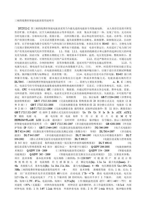
1.2 工作原理简述本产品由电压、电流互感器、高精度高速模数转换器、高速数据处理器、实时时钟、数据接口设备和人机接口设备组成。
在高速数据处理器的控制下,高速模数转换器将来自电压、电流互感器的模拟信号转换为数字信号,并对其进行数字积分运算和误差补偿,从而精确地获得有功电量和无功电量,并依据相应费率和需量等要求对数据进行处理。
其结果保存在数据存储器中,并随时向外部接口提供信息和进行数据交换,其原理框图如图1所示。
图1:工作原理简述(以三相四线表为例)1.3 技术参数1.3.1主要技术参数1.3.2日历时钟1.3.3光耦脉冲输出1.3.4其它数据2仪表主要功能2.1 分时计量本仪表有两种配置:TH及TF型。
TH型为双方向电能表,它可以计量正、反向有功,感、容性无功及四象限无功电能。
TF型为单方向电能表,它可以计量正向有功及感、容性无功电能,反向有功计量精度不作保证,仅供参考。
两种配置的各种电能均可以按最大五种费率时段进行分时计量。
五种时段的名称为:尖、峰、平、谷、脊谷。
时间的设定以年为大周期,一年分为几个时区,每个时区内以天为小周期,一天分为几个时段,每个时段对应一种费率。
对于部颁规约一年最多可设置14个切换时区,最多可有12套不同的时段表,每日的切换数最大为14。
2.2 最大需量TH型电表可计算正、反向有功,感、容性无功最大需量及其出现时间,TF型电表可计算正向有功,感、容性无功最大需量及其出现时间。
两种配置均可以计量五种费率的最大需量及其发生时间。
最大需量的积分周期和滑差步进时间可选择,出厂设置为:周期15分钟,滑差步进时间为1分钟。
2.3 按月统计电量本仪表除给出上述有、无功当前总及分时电量,还给出了上1月到上9月(月数可以设置,默认为3个月,最多为9个月)的电量。
兰吉尔电度表ZQ中文用户手册(H01)
2.5.1
电表的测量系统采用模拟电流值I1、I2、I3和模拟电压值U1, U2, U3作为输入信号。
2.5.2
电压输入
高阻抗分压器把施加在电表上的电压U1、U2、U3(57.7伏至132.8伏)成比例地降低到几毫伏(UU),进行进一步处理。
电流输入
同样,补偿电流互感器也降低施加在电表上的输入电流I1、I2、I3(0 A至2 A或0 A至7.5 A)。这些电流互感器的次级电流提高负载电阻器的电压。上述电压值与输入电流成比例,也是几毫伏(UI)。
如果电表遭受到流动的水或高压装置的侵害,如冲洗等,电表可能会损坏。可以用湿布清洁电表。
更换电池
警告
换上了错误型号或额定电压的电池,可能会损坏电表。
只允许把电池更换为额定电压为6伏并与原电池(型号:CR-P2)结构相同的锂电池。
如果电表与供电网长时间断开,备用功率会耗尽。当备用功率耗尽时更换电池,可能会产生无效的时间/日期信息,但不会产生相应的错误信息。
可以更改电流互感器的负载电阻器,使电表量程与所需的电流范围(1安或5安)相匹配。
2.5.3
使用模数转换器把模拟输入信号UU和UI转换为数字值,并使用各种过滤器过滤。
接着,就可以获得所有三相的电压(U)和电流(I)的数字瞬间值,这些值用于信号处理器生成数字原始值。
2.5.4
每隔0.2秒,信号处理器计算一次有功电量、无功电量和视在功率以及各种瞬时量,如相电压和相电流等。一般说来,ZMQ的测量系统和ZCQ产生单相数据,而ZFQ提供其两个测量元件相应的数据。
这些值是经过校验的原始数据,它们存储在信号处理器的输出缓冲器中,通过一个SPI接口把它们从输出缓冲器传送到微处理器中进一步运算。
单相电量计算
QP452-VER2.1智能配电仪表使用手册

电流端子
R S 4 85端 子
32
14
V3 V2 V1 VN
C
B
AN
电压 输入
D I端子
7
6
5
G
N
L
电源地 零线 火线
辅助 电源
89 I 11 I12 + A相
10 11 I21 I22 + B相 电流输入
12 13 I31 I32 + C相
DO端子(继电器)
14 15
+
-
485A 485B
RS-485
CAUTION
通讯连接应使用带有铜网的屏蔽双绞线,线径不小于0.5mm2(美国型号:AWG18, 中国型号:RVVP 1x2X0.5mm2)。布线时应使通讯线远离强电电缆或其他强电场环境。
-- 6 --
安装 接线 及 接线 端子 介 绍(※在某些型号中,无电压信号,则电压端空置即可。)
电压端子
电源端子
物体。 ·当 移除或安 装面 板时注 意不要碰 到电 母线,避免操 作面板,以免造成个 人伤害。 ·这 个设备的 成功 运行依 赖于正确 的处 理,安装的操 作。忽略基本的安装 要求可能造成 个人 的
伤 害,也可能损坏电气 设备或者其它 物体 。 ·对 装有智能 配电 仪表的 设备作绝 缘测 试时,断开所 有与其连接的输入和 输出线。高压 试验 可
技术规格参数
输入信号 ◆ 输入电压 - 额定值:100V或220VAC/DC,允许25%的超限 - 过负荷:2倍额定值(连续);2500VAC/1秒(不循环) - 测量形式:True-RMS - 负荷:小于0.2VA
◆ 输入电流 - 额定值:5A(1A可选),允许20%的超限 - 过负载:2倍额定值;100A/1秒(不循环) - 测量形式:True-RMS - 负荷:小于0.2VA
DTZY25 三相费控智能电能表 操作手册 2010-08-26

内嵌高速高精度的交流电压电流采集模块,采样精度高,电能计量实时精确;
能分时计量组合有功电量,正、反有功电量及需量、组合无功,四象限无功电量,并具有485通讯、红外通讯等功能;
内嵌保密性高的ESAM模块,以实现电表与系统主站之间的安全认证过程,保证与系统主站进行数据交互的安全性和完整性;
电磁兼容性能优良,能抵御高压尖峰脉冲、强磁场、强静电、雷击浪涌的干扰、且具有较强的温度自适应能力;
电池容量
≥1200mAh
停电后数据保存时间
≥10年(用新电池)
气候条件:
正常工作温度
-25℃~+60℃
极限工作温度
-40℃~+70℃
贮存和运输温度
-40℃~+70℃
贮存和工作湿度
≤85%
技术参数:
费率数
4
时段数
14
计度范围
-799999.99 kWh~799999.99 kWh , -799999.99 kvarh~799999.99 kvarh
图中CPU用于分时计费和处理各种输入输出数据,通过串行接口将专用电能芯片的数据读出,并根据预先设定的时段完成分时电能计量和最大需量计量功能,根据需要显示各项数据、通过红外或485接口进行通讯传输,并完成运行参数的监测,记录存储各种数据。
二、外形说明及安装
2.1
图2三相费控智能电能表外形图说明
翻开透明翻盖,右边有一块小盖板,打开小盖板可见一个电池槽,电池槽中安装有两节3V锂电池,供停电唤醒时使用(电表内部已焊有一节3.6V时钟电池用于维持内部数据不变及时钟运行)。安装时注意电池的正、负极方向。小盖板下方有一个按键为编程按键。
电流标识,分别代表Ia、Ib、Ic,功率反向时显示“-”号。失流时闪烁显示;当某相断流时该相电流标识消失(包括“-”号)。注:在三相三线表中,无B相电流。
- 1、下载文档前请自行甄别文档内容的完整性,平台不提供额外的编辑、内容补充、找答案等附加服务。
- 2、"仅部分预览"的文档,不可在线预览部分如存在完整性等问题,可反馈申请退款(可完整预览的文档不适用该条件!)。
- 3、如文档侵犯您的权益,请联系客服反馈,我们会尽快为您处理(人工客服工作时间:9:00-18:30)。
文档历史记录
原稿编写人:王元元 发布时间:2009-6-26 修订记录:
版本
修订时间
V1.0 2009-6-26
V1.1 2009-7-17
V1.2 2011-1-5
修订人 王元元 何斌 曲岩
修订内容
创建文档
增加所有权编号注释 修改负荷曲线通道数、修改 3P3W 接线图 增加误差补偿、谐波、基波功能说明及应用
工程部文件
WU.TE432q 高精度 关口电能表用户 培训手册 V1.2
文件编号: EM-02-14
版 本:
V1.2
日 期:
2011-1-5
工程部内部文件,请勿外传
编 写: 校 对: 审 核: 批 准:
王元元 杨帆 何斌 叶军
WU.TE432q 高精度关口电能表用户培训手册 V1.1
上海惠安系统控制有限公司
文件编号:EM-02-14
第 2 页 共 40 页
WU.TE432q 高精度关口电能表用户培训手册 V1.1
目录பைடு நூலகம்
上海惠安系统控制有限公司
一、 概 述 ................................................................................................................................................5 1.1 主要特点 ............................................................................................................................................5 1.2 60 年的表计制造历史 ......................................................................................................................6 二、 结构 .................................................................................................................................................6 2.1 计量原理 ............................................................................................................................................6 2.4 维护保养 ..........................................................................................................................................8 三、电能表的组成部件 ..........................................................................................................................8 3.1 外壳及电表的安装尺寸 ...................................................................................................................8 3.2 前面板 ................................................................................................................................................9 3.3 电表接线图 ......................................................................................................................................10 3.4 辅助接线端子 ..................................................................................................................................11 3.5 LED 脉冲指示器.............................................................................................................................11 3.6 红外光电接口 ..................................................................................................................................11 3.7 电源 ..................................................................................................................................................11 四、 模块 ...............................................................................................................................................11 4.1 输入/输出(I/O)模块 ....................................................................................................................12 4.2 通信模块 ..........................................................................................................................................12 五、显示 ................................................................................................................................................12 5.1 按键 ..................................................................................................................................................13 5.2 状态指示 ..........................................................................................................................................13 5.3 表计起始标志模式 ..........................................................................................................................14 5.4 自动循显模式 ..................................................................................................................................14 5.5 LCD 测试模式 ................................................................................................................................14 5.6 寄存器模式 ......................................................................................................................................15 5.7 电网参数显示 ..................................................................................................................................15 5.8 表计设置模式 ..................................................................................................................................15 5.9 按键流程图 ......................................................................................................................................16 5.10 现场抄表简单说明 ........................................................................................................................18 六、实时时钟(RTC)........................................................................................................................ 21 6.1 后备电源 ..........................................................................................................................................21 6.2 时间设置 ..........................................................................................................................................21 七、 电能量计量 ...................................................................................................................................21