优利德非接触式红外体温计UT300E操作说明书
红外线测温仪使用指南
红外线测温仪使用指南一、引言红外线测温仪是一种非接触式温度测量设备,通过测量物体辐射的红外线能量来获取物体的温度。
本文旨在为用户提供关于红外线测温仪的详细使用指南,帮助用户正确、高效地操作红外线测温仪。
二、红外线测温仪的基本原理红外线测温仪利用物体辐射的红外线能量来测量温度,其基本原理是根据物体的表面温度与发射出的红外线能量之间的关系来计算温度数值。
红外线测温仪通过感应物体表面的红外线能量,并将其转换为温度值,在显示屏上进行显示。
三、红外线测温仪的使用步骤1. 准备工作:确保红外线测温仪电池电量充足,并将其插入设备。
一些红外线测温仪需要进行校准,请在使用前按照说明书操作进行校准。
2. 打开红外线测温仪:按下电源开关,等待片刻,红外线测温仪会自行启动,显示屏上会显示一些基本信息,包括电池电量、设备型号等。
3. 设置测量模式:根据需要,选择红外线测温仪的测量模式。
大部分红外线测温仪提供单点测温、连续测温等多种模式,可根据具体使用场景进行选择。
4. 瞄准目标物体:将红外线测温仪对准待测物体的表面。
通常需要保持一定的距离,根据红外线测温仪的说明书来确定最佳测量距离。
5. 按下测量键:在瞄准目标物体后,按下测量键,红外线测温仪会接收并处理物体辐射的红外线能量,并将其转化为温度数据,并在显示屏上显示结果。
四、红外线测温仪的使用注意事项1. 距离问题:在测量时,应保持一定的距离,同时要避免测量过程中的物体阻挡红外线测温仪的视野。
2. 温度范围:了解红外线测温仪的测量温度范围,避免在超出其范围的温度区间进行测量。
3. 环境影响:红外线测温仪对周围环境的影响较大,如强光、尘埃等可能会干扰测量结果,应尽量避免这些干扰。
4. 反射问题:在测量金属表面温度时,可能会因为金属的高反射性而得到不准确的结果,请注意识别和排除这种情况。
5. 温度修正:某些红外线测温仪具有温度修正功能,可根据环境温度进行修正,以提高测量精度。
在需要时,可以参考设备说明书进行操作。
Uni-Trend UT303A B C D E 红外温度计说明书
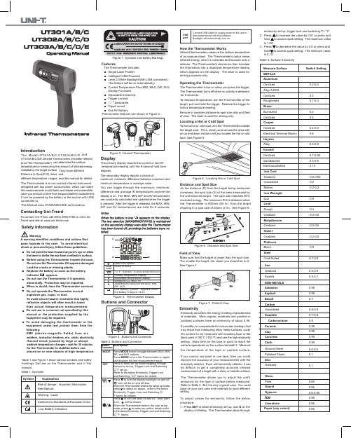
EmissivityDistance and Spot SizeField of ViewTo contact Uni-Trend. call (852) 2950 9168 or visit Uni-Trend web site at IntroductionThe Model UT301A/B/C,UT302A/B/C/D andUT303A/B/C/D/E Infrared Thermometers (hereafter referred to as "the Thermometer")can determine the surfacetemperature by measuring the amount of infrared energy radiated by the target surface. They have different Distance to Spot(D:S) ratios anddifferent temperature ranges, read the manual for details.The Thermometer is a non-contact infrared instrument designed with low power consumption, which can make the measurements much faster and easier and meanwhile save you amount of time from frequent battery replacement. It can be powered by the battery or the source with USB connected to.This Manual uses UT303A/B/C/D/E as illustration.Contacting Uni-TrendWarningA warning identifies conditions and actions that pose hazards to the user. To avoid electrical shock or personal injury, follow these guidelines:●●●●●●●●●●●●●●●●● Do not point the laser toward anyone's eye or allow the laser to strike the eye from a reflective surface.Before using the Thermometer inspect the case. Do not use the Thermometer if it appears damaged. Look for cracks or missing plastic.Replace the battery as soon as the batteryindicator appears.Do not use the Thermometer if it operatesabnormally. Protection may be impaired.When in doubt, have the Thermometer serviced.Do not operate the Thermometer aroundexplosive gas, vapor, or dust.To avoid a burn hazard, remember that highly reflective objects will often result in lower than actual temperature measurements.Do not use in a manner not specified by this manual or the protection supplied by the equipment may be impaired.To avoid damaging the thermometer or the equipment under test protect them from the following:EMF (electro-magnetic fields) from arc welders, induction heaters, etc; static electricity;thermal shock (caused by large or abrupt ambient temperature changes-- wait for 30 minutes for the Thermometer to stabilize before use;placed on or near objects of high temperature.Table 1 and Figure 1 show various symbols and safety markings that are on the Thermometer and in this manual.Table 1. Symbols Figure 1. Symbols and Safety MarkingsFeaturesThe Thermometer includes:Single Laser Pointer Intelligent USB-PoweredLevel 2 White Backlight(With USB connected,) this feature will be on automatically).Current Temperature Plus MIN, MAX, DIF, AVG Display Functions Adjustable Emissivity Trigger Locked ℃/℉Selectable Tripod mount One 9V BatteryThermometer features are shown in Figure 2.DisplayThe primary display reports the current or last IR temperature reading until the 8-second hold time elapses.Figure 2. Infrared ThermometerThe secondary display reports a choice ofmaximum, minimum, difference between maximum and minimum temperature or average value.You can toggle through the maximum, minimum,difference and average IR temperatures anytime the display is on. The MAX, MIN, DIF and AV temperatures are constantly calculated and updated when the trigger is pressed. After the trigger is released, the MAX, MIN,DIF and AV temperatures are held for 8 seconds.Figure 3. Thermometer DisplayConnect USB cable for supply power to the unit or data transmission with the software;Backlight will automatically turn on;USB portHow the Thermometer WorksInfrared thermometers measure the surface temperature of an opaque object. The Thermometer's optics sense infrared energy, which is collected and focused onto a detector. The Thermometer's electronics then translate the information into a displayed temperature reading which appears on the display. The laser is used for aiming purposes only.Operating the ThermometerLocating a Hot or Cold SpotThe Thermometer turns on when you press the trigger. The Thermometer turns off when no activity is detected for 8 seconds.To measure temperature, aim the Thermometer at the target, pull and hold the trigger. Release the trigger to hold a temperature reading.Be sure to consider distance-to-spot size ratio and filed of view. The laser is used for aiming only.To find a hot or cold spot, aim the Thermometer outside the target area. Then, slowly scan across the area with an up and down motion until you located the hot or cold spot. See Figure 5.Figure 5. Locating Hot or Cold SpotAs the distance (D) from the target being measured increases, the spot size (S) of the area measured by the unit becomes larger. The spot size indicates 90%encircled energy. The maximum D:S is obtained when the Thermometer is 600mm (60 in) from the target resulting in a spot size of 20mm (2 in). See Figure 6.Figure 6. Distance and Spot SizeMake sure that the target is larger than the spot size.The smaller the target, the closer you should be to it.See Figure 7.Figure 7. Field of ViewEmissivity describes the energy-emitting characteristics of materials. Most organic materials and painted or oxidized surfaces have an emissivity of about 0.95.If possible, to compensate for inaccurate readings that may result from measuring shiny metal surfaces, cover the surface to be measured with masking tape or flatblack paint (<150 o oC / 302 F) and use the high emissivity setting. Allow time for the tape or paint to reach the same temperatures as the surface beneath it. Measure the temperature of the tape or painted surface.If you cannot use paint or use tape, then you could improve the accuracy of your measurements with the emissivity selector. Even with emissivity selector, it can be difficult to get a completely accurate infrared measurement of a target with a shiny or metallic surface.The Thermometer allows you to adjust the unit's emissivity for the type of surface before measured.Refer to Table 3. But it is only a typical case. You could base on your own case and materials to have different setting.To adjust values for emissivity, follow the below procedure:1. 2.3.Press SET to select emissivity set up, icon E on the display is blinking. The Thermometer steps throughemissivity set up, trigger lock and switching o C / oF.Press to increase the value by 0.01 or press and hold to access quick setting. The maximum value is 1.00.Press to decrease the value by 0.0 or press and hold to access quick setting. The minimum value is 0.10.Table 3. Surface Emissivity Measure Surface METALS Aluminum Oxidized Alloy A3003Oxidized Roughened Brass Burnished Oxidized Copper OxidizedElectrical Terminal Blocks Haynes AlloyInconel Oxidized Sandblasted Electoropolished Switch Setting0.2-0.40.30.1-0.30.30.50.4-0.80.60.3-0.80.7-0.950.3-0.60.15Iron Cast Oxidized Unoxidized Molten Iron Wrought Dull Lead Rough Oxidized Molydbenum Oxidized NickelOxidized PlatinumBlack Steel Cold-Rolled 0.6-0.950.20.2-0.30.90.40.2-0.60.2-0.60.2-0.50.90.7-0.9Iron Oxidized Rusted NON-METALS Asbestos Asphalt BasaltCarbon Unoxidized Graphite Carborundum Ceramic Clay Concrete Cloth 0.5-0.90.5-0.70.950.950.70.8-0.90.7-0.80.90.950.950.950.95Ground Sheet Polished Sheet Zinc OxidizedGlass Plate Gravel GypsumIceLimestone Paper (any colour)0.4-0.60.10.10.850.950.8-0.950.980.980.95Plastic Opaque Soil WaterWood, (natural)0.950.9-0.980.930.9-0.95Measure Surface Switch SettingP/N:110401104253XT o lock or unlock the trigger, follow the below procedures:1. Press SET to select trigger lock setting, theis blinking.2. Press to select ON or OFF.When the trigger is locked, the Thermometer is on for continuous measurement, there is no need to pull the trigger.When the trigger is unlocked, user needs to pull the trigger for measurement. When you release the trigger,the Thermometer will keep hold the measurement result automatically.1. Press SET to choose o C / o F selection mode,2. Press to select o C or o F.The display will remain activated 8 seconds after the trigger is released. HOLD appears in the upper middle of the display. When the trigger is pulled again, the Thermometer will begin measuring in the last function selected.Typical MeasurementsThis section describes a variety of measurements often performed by technicians.User could select to turn on or off the backlight andlaser whenever you are making readings with the Thermometer. But if you are using USB to power up the Thermometer, the Level 2 white backlight will be on automatically.Relatively high emissivity normally means emissivity setting of about 0.95.Relatively low emissivity normally means emissivity setting of about 0.30.When user cannot identify the emissivity of the object Trigger LockSwithingHOLD●●●●Tips:to be measured, user could cover the surface to bemeasured (temperature >150oC) with black electric tape (emissivity of about 0.95). Allow time for the tape to reach the same temperature as the object to be measured. Measure and record the temperature of the tape.Target the Thermometer to the object to be measured, adjust the emissivity setting to make it as the same temperature as the tape. At this time, the Thermometeremissivity setting is close to the emissivity of the object to be measured, measurement could be started.1.2.3.4.Press SET to select emissivity. Press / to select relatively low emissivity for bright contacts, or 0.7mid level for darkened contacts.Press MODE to select MAX.Measure line and load side of one pole without releasing trigger.A temperature difference between the line and load sides of a pole indicate increased resistance of one point and a contactor may be failing.1.2.3.4.5.Press SET and then press / to set emissivity to relatively low for uninsulated connectors or relatively highfor plastic encased relays or for bakelite enclosed relays or insulated connectors.Press MODE to select MAX.Start to scan.Measure the relay casing, looking for hot spots.Measure electrical connections on relay terminals looking for hot spots.1.2.3.4.5.Press SET and then press / to set emissivity torelatively high for paper covered fuse body or insulated connections.Press MODE to select MAX.Scan the paper covered length of fuse.Without releasing the trigger, scan each fuse.Unequal temperatures between fuses may indicate voltage or amperage imbalance.Press SET and then press / to set emissivity to relatively low, for metal fuses and caps and insulated Testing Contactors (Starters)Testing Enclosed RelaysTesting Fuses and Buss Connections6.7.buss connections.Press MODE to select MAX.Scan each end cap on each fuse/Press SET and then press / to set emissivity to relatively low for uninsulated connectors or buss connections or relatively high for insulated connections.1.Scan the conductor, moving toward direction of electrical connector (quick connect, wire nut, buss connection, or lug).2.Turn off heating, cooling, and blower.Press SET to select emissivity. Press / to selectemissivity relatively high for painted surfaces or window surfaces.Press MODE to select MIN when opposite side ofwall is at lower temperature and or select MAX when opposite side of wall is at higher temperature.Measure an interior partition wall surface temperature.Do not release the trigger. Record this temperature as your baseline (or benchmark) for a ìperfectlyîinsulated wall.Face the wall to be scanned. Stand 1.5m away toscan a 5cm spot on the wall.Scan horizontal rows of wall from top to bottom, orhorizontal rows of ceiling from wall to wall. Look for greatest deviations from baseline temperature to identify problems. This completes the insulation test scan.1.2.3.4.5.6. Testing Electrical ConnectionsScanning Walls for Air Leaks or Insulation DeficienciesTurn on the blower (no heat, no cooling) and retest. If test results with the blower on are different than results with the blower off, this may indicate air leaks in conditioned envelope walls. The air leaks are caused by duct leaks that create a pressure differential across the conditioned space envelope.WarningTo avoid injury when testing bearings:Do not wear loose clothing, jewelry, or anything around neck when working around moving parts such as motors, belts, blower, andfans.Make sure an electrical disconnect is within reach and operatingcorrectly and freely.Do not work alone.Press SET and then press / to select relatively high emissivity.Press MODE to select MAX.Enable motor and allow it to reach steady state operating temperatures.Disable the motor if possible.Measure the two motor bearing temperatures Compare the two motor bearing temperatures.Unequal temperatures or a high temperature can indicate a lubrication or other bearing problem that is resulting from excess friction.Repeat the sequence for the blower bearings.1.2.3.4.5.6.7.●●●Testing Belts and SheavesChecking Hydronic Radiant Heat ApplicationsMeasuring Grille,Register,or Diffuser Discharge TemperaturePress SET and then press / to select relatively high emissivity.Press MODE to select MAX.Enable the motor and allow it to reach a steady state operating temperatures.Aim the Thermometer at the surface to be measured.Start recording temperatureSlowly move the Thermometer up the belt toward second sheave.1.2.3.4.5.6.If belt is slipping, sheave temperature will be high from friction.If belt is slipping, belt temperature will remain high between sheaves.If belt is not slipping, belt temperature will reduce between sheaves.If inner surfaces of sheaves are not a true ìVîshape, this indicates belt slippage and will continue to operate at elevated temperatures until sheave is replaced.Sheaves must be properly aligned (include ìpitch & yawî) for belt and sheaves to operate at appropriate temperatures. A straight edge or taut string, can be used to check alignments.Motor sheave should operate at a temperature consistent with blower sheaves.If motor sheave is at a higher temperature at motor shaft than at outer circumference, belt is probably not slipping.If outer circumference of sheave is at higher temperature than sheave at motor shaft, then belt is probably slipping and sheaves may be misaligned.●●●●●●●● 1.2.3.4.Press SET and then press / to select relatively high emissivity.Press MODE to select MAX.To locate radiant heat tubes in floor, temporarily elevate the loop temperature to create hotter spots for identifying tubing runs.Before releasing trigger, press MODE to toggle between MIN, MAX, DIF floor temperatures and record the temperature for future comparison and trending under similar conditions.Radiant heat tubes in the floor will normally run parallel to the outside walls. Starting at the floor wall juncture,scan parallel to the wall while moving into the room away from the wall. Parallel to the outside wall you should find parallel isothermal rows indicating the location of heat tubes below the surface. Perpendicular to the outside wall, you should find rising and falling temperatures at equal distances. High temperatures indicate you are scanning a heat tube beneath the floor surface, low falling temperatures indicate a space between the heat tubes.1.2.3.4.5.Press SET and then press / to select relativelyhigh emissivity.Aim the Thermometer at the discharge air grille,register, or diffuser.Measure discharge temperature.Release trigger to freeze the temperature readingfor 8 seconds and record this temperature.Grille, register, or diffuser temperature should beequivalent to discharge temperature at the airhandler.1.2.3.4.5.6.Remove panels to gain access to coil return bends or hairpins.Press SET and then press / to select relatively high emissivity for copper tube.Start the refrigeration system.Aim the Thermometer at coil turn bends/hairpins.Start recording temperature.Take temperature of each return bend/hairpin.All evaporator return bends/hairpins should be at or slightly above evaporator saturation temperature from the pressure/temperature chart.All condenser return bend/hairpins should be at or slightly less than condenser saturation temperature.If a group of return bends/hairpins do not conform to expected temperatures, that indicates a blocked or restricted distributor or distributor tube.MaintenanceChanging the BatteryCleaning the LensCleaning the HousingTo install or change the 9V battery, open the battery compartment the battery as shown in Figure 2.Blow off loose particles using clean compressed air.Carefully wipe the surface with a moist cotton swab.The swab may be moistened with water.Use soap and water on a damp sponge or soft cloth.avoid damaging the Thermometer, do NOT submerge it in water.●●●Checking for Blockage in Air-To-Air Evaporators or CondensersTable 4. Troubleshooting The Thermometer conforms to the following standards:● EN61326-1 EMC ● EN60825-1 SafetyCertification testing was conducted using a frequency range of 80 to 100MHz with instrument in three orientations.TroubleshootingCE CertificationMeasurement Range (UT301A): -18o C to 350o (0o F to 662o F)Measurement Range (UT301B): -18o C to 450o (0o F to 842o F)Measurement Range (UT301C): -18o C to 550o (0o F to 1022o F)Measurement Range (UT302A): -32o C to 450o (-26o F to 842o F)Measurement Range (UT302B): -32o C to 550o (-26o F to 1022o F)Measurement Range (UT302C): -32o C to 650o (-26o F to 1202o F)Measurement Range (UT302D): -32o C to 1050o (-26o F to 1922o F)Measurement Range (UT303A): -32o C to 650o (-26o F to 1202o F)Measurement Range (UT303B): -32o C to 850o (-26o F to 1562o F)Measurement Range (UT303C): -32o C to 1050o (-26o F to 1922o F)Measurement Range (UT303D): -32o C to 1250o (-26o F to 2282o F)Measurement Range (UT303E): -32o C to 1550o (-26o F to 2822o F)Spectral Range : 8 to 14 microns Accuracy: 1.8% or (1.8o C/4o F)Temperature than less 0o C , Accuracy add to 1o C(2o F)(Assumes ambient operating temperature of 23 to o 25 C (73 to 77o F))Repeatability : 0.5% of reading or 1o C/2o F Response Time (95%) : 250ms Distance to Spot (D:S) (UT301A/B/C): 12:1Distance to Spot (D:S) (UT302A/B/C/D): 20:1Distance to Spot (D:S) (UT303A/B/C/D/E): 30:1SpecificationsInfraredCCCCCCCCCCCCSighting: Single point laserPower: Class 2 (II) operation; Output <1mV, wavelength630 to 670mmPower Supply : 6F22 9V BatteryPower Consumption : At least 30 hours battery life(Alkarine), At least10 hours battery life (General Purpose)Weight : 0.322kgSize : 17.69cm (H) x 16.36 cm (L) x 5.18cm (W)Operating Temperature Range: 0o C to 50o (32o F to 120o F)Relative Humidity : 0 to 75% noncondensingStorage Temperature : -20o C to 65o C (-4o F to 150o F)Emissivty Adjustment : 0.10~1.00Display Resulation :0.1o C (0.1o F)Secondary Display Information :Maximum, Minimum,LaserElectricalPhysicalEnvironmentalDifferential, AverageCThis operating manual is subject to change without notice.** END **。
红外线测温仪操作规程
红外线测温仪操作规程一、引言红外线测温仪是一种非接触式温度测量设备,通过测量物体发出的红外辐射来获取其表面温度。
本操作规程旨在指导操作人员正确、安全地使用红外线测温仪,以确保测量结果的准确性和人员的安全。
二、设备准备1. 确保红外线测温仪处于正常工作状态,检查仪器的电源和电池电量。
2. 根据需要选择合适的测量模式,如单点测量、连续测量等。
3. 保持测量距离在仪器的有效测量范围内,避免过远或者过近的测量距离。
三、操作步骤1. 打开红外线测温仪的电源,确保显示屏正常工作。
2. 根据需要选择合适的温度单位,如摄氏度或者华氏度。
3. 瞄准待测物体的表面,保持仪器与物体垂直,并保持一定的距离。
4. 按下测量按钮,观察仪器显示屏上的温度数值。
5. 如需连续测量,可按住测量按钮并挪移仪器,以获取更多点的温度数据。
6. 完成测量后,及时关闭红外线测温仪的电源。
四、注意事项1. 不要将红外线测温仪暴露在高温或者低温环境中,以免影响仪器的准确性和寿命。
2. 避免将红外线测温仪指向有强烈光源的物体,以免干扰测量结果。
3. 在测量过程中,确保红外线测温仪与待测物体之间没有遮挡物,以免影响测量精度。
4. 注意避免测量过程中的震动和颤动,以确保测量结果的准确性。
5. 在使用红外线测温仪时,注意保持仪器的清洁和干燥,避免污染和水分进入仪器。
6. 如需测量不同物体的温度,应在测量前进行标定,以确保测量结果的准确性。
五、故障排除1. 若红外线测温仪无法正常启动或者显示异常,首先检查电源和电池是否正常,如有必要更换电池。
2. 若测量结果异常或者不稳定,可尝试重新对待测物体进行瞄准,或者将仪器进行标定。
3. 若仪器浮现其他故障,建议联系维修人员进行维修或者更换。
六、安全注意事项1. 在使用红外线测温仪时,应注意保护自己的眼睛,避免直接将红外线照射到眼睛。
2. 不要将红外线测温仪用于危(wei)险环境或者易爆环境。
3. 在使用红外线测温仪时,应遵守相关安全操作规程,确保自身安全和他人安全。
红外测温仪操作使用方法
红外测温仪操作使用方法1.操作测温仪测温仪会在按下扳机或按下黄色键时打开。
若连续8秒钟内没有检测到活动,测温仪会自动关闭。
测量温度时,将测温仪瞄准目标,拉起并保持扳机按下不动。
松开扳机以保持温度读数。
一定要考虑距离与光点尺寸比以及视场。
激光仅用于瞄准目标物体。
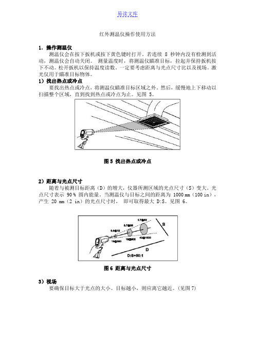
1)找出热点或冷点要找出热点或冷点,将测温仪瞄准目标区域之外。
然后,缓慢地上下移动以扫描整个区域,直到找到热点或冷点为止。
见图 5。
图5 找出热点或冷点2)距离与光点尺寸随着与被测目标距离(D)的增大,仪器所测区域的光点尺寸(S)变大。
光点尺寸表示 90 % 圆内能量。
当测温仪与目标之间的距离为 1000 mm(100 in),产生 20 mm(2 in)的光点尺寸时,即可取得最大 D:S。
见图 6。
图6 距离与光点尺寸3)视场要确保目标大于光点的大小。
目标越小,则应离它越近。
(见图7)图7 视场4)发射率发射率表征的是材料能量辐射的特征。
大多数有机材料和涂漆或氧化处理表面的发射率大约为 0.95。
如果可能,可用遮蔽胶带或无光黑漆(< 150 ℃/302℉)将待测表面盖住并使用高发射率设置,补偿测量光亮的金属表面可能导致的错误读数。
等待一段时间,使胶带或油渍达到与下面被覆盖物体的表面相同的温度。
测量盖有胶带或油漆的表面温度。
如果不能涂漆或使用胶带,可使用发射率选择器来提高您的测量准确度。
即使是使用发射率选择器,对带有光亮或金属表面的目标也很难取得完全准确的红外测量值。
5)用户设置操作SET键:循环切换设置状态,循环次序为发射率设定锁定测量设定℃/℉选择设定正常测量。
按黄色键可直接保存设置并退出。
6)发射率设定此功能为改变发射率的值。
设定时“E=0.”字样闪烁。
单击▲递加0.01,长按快速增加,当加到1.00后停止。
单击▼递减0.01,长按快速减少,当减到0.10后停止。
可根据不同被测物体设置相应的发射率。
请参见表2。
表内所列的发射率设置为对典型情况的建议。
优利德 UTE300系列数字功率计数据手册 说明书

系列数字功率计版本:REV.1日期:2024.08.08◆交直流电压量程:UTE310/UTE310G:15V,30V,60V,150V,300V,600VUTE310H/UTE310HG:15V,30V,60V,150V,300V,600V.1000V◆交直流电流量程:UTE310/UTE310G:5mA,10mA,20mA,50mA,100mA,200mA,500mA,1A,2A,5A,10A,20AUTE310H/UTE310HG:1A,2A,5A,10A,20A,50A◆交直流功率范围:UTE310/UTE310G:75mW~12000WUTE310H/UTE310HG:15W~50000W◆频率测量:0.1Hz~300kHz◆积分功率:0~10000小时◆四则运算:A+B,A-B,AxB,A/B,A/B^2,A^2/B◆谐波测量:1~50次◆波形显示:电压,电流◆外部传感器:电流◆DAC输出:U、I、P、S、Q、LAMBda、PHI、FU、FI、UPK、IPK、WH、WHP、WHM、AH、AHP、AHM、MATH图形化的用户界面,操作简单方便;更有帮助系统,方便信息获取;USB数据存储;一屏多显数据功能;支持U盘存储,便于数据文件管理;支持U盘系统在线升级,便于产品的系统维护升级。
◆科研教育◆生产现场的高速测量◆实验室和研发测量◆照明电器◆电动工具◆家用电器◆电机、电热器具等领域生产企业的生产线◆ 4.3寸TFT-LCD 显示分辨率480*272◆电压电流有效值的测量范围:UTE310/UTE310G: 15mV~600V / 25uA~20AUTE310H/UTE310HG: 15mV~1000V / 10mA~50A◆电压电流最高分辨率: 1mV/0.1uA◆电压电流及功率基本精度: 0.1%◆功率最高分辨率:0.001mW◆测量带宽:0.1Hz~300kHz◆采样率:1MHz◆丰富的通信接口:USB 、RS-232或GPIB(可选)、LAN◆支持Modbus和SCPI通讯协议◆电压电流波形显示、谐波图形显示、用于测量记录的D/A输出、比较器功能、电流传感器输入、USB数据存储4.3寸TFT彩屏多参数一屏显示300kHz 模拟带宽,捕获更高频信号1MHz 采样率,瞬变信号测量更精准50次谐波支持IEC61000-4-7标准UTE310/UTE310GUTE310H/UTE310HG零电平补偿或量程改变后,温度变化带来的的影响DC电压:在DC电压精度上增加量程的0.02%/℃。
红外线测温仪操作规程

红外线测温仪操作规程一、引言红外线测温仪是一种用于非接触式测量物体表面温度的设备,广泛应用于工业、医疗、安防等领域。
本操作规程旨在规范红外线测温仪的正确使用方法,以确保测量结果的准确性和操作人员的安全。
二、设备准备1. 确保红外线测温仪处于正常工作状态,电池电量充足。
2. 清洁测温仪的测量窗口,确保无污垢或障碍物。
3. 根据需要,选择合适的测温模式和单位(摄氏度或华氏度)。
三、测温操作步骤1. 打开红外线测温仪的电源开关,等待设备初始化完成。
2. 确保测温仪与被测物体之间无遮挡物,并保持一定的距离(通常为测量距离的2倍)。
3. 对准被测物体,将测温仪的测量窗口对准物体表面,确保窗口与物体垂直。
4. 按下测温按钮,触发测量动作。
在测量过程中,保持测温仪的稳定,避免晃动或抖动。
5. 等待测温仪完成测量,读取显示屏上的温度值。
四、注意事项1. 在测量过程中,避免将红外线测温仪直接对准明亮的光源或强烈的辐射源,以免干扰测量结果。
2. 避免在强风、强烈的电磁场或电源干扰下进行测量,以确保测量结果的准确性。
3. 若被测物体表面有涂层、反射性较强或不均匀的情况,应注意可能会影响测温结果的准确性。
4. 在连续测量多个物体时,应等待测温仪的温度稳定后再进行下一次测量。
5. 使用完毕后,及时关闭红外线测温仪的电源开关,以节约电池的使用寿命。
五、维护与保养1. 定期清洁测温仪的测量窗口,使用干净的软布擦拭,避免使用化学溶剂或尖锐物品。
2. 长期不使用时,应将红外线测温仪存放在干燥、通风的环境中,避免受潮或受热。
3. 如发现测温仪存在异常或故障,应立即停止使用,并联系维修人员进行检修或维护。
六、安全注意事项1. 在使用红外线测温仪时,应遵循相关的安全操作规定,确保操作人员的安全。
2. 避免将红外线测温仪直接对准人体眼睛或其他敏感部位,以免对健康造成损害。
3. 在使用过程中,应注意设备的热量散发,避免触摸测温仪的热表面,以防烫伤。
红外线测温仪操作规程
红外线测温仪操作规程一、引言红外线测温仪是一种用于非接触式测量物体表面温度的仪器,广泛应用于工业、医疗、环境监测等领域。
为了正确、安全地操作红外线测温仪,本文将详细介绍红外线测温仪的操作规程。
二、仪器概述红外线测温仪由测温部份和显示部份组成。
测温部份包括红外线接收器、光学系统和温度传感器,用于接收并转换物体表面的红外线辐射能量。
显示部份包括显示屏、控制按钮和电源开关,用于显示测量结果和操作仪器。
三、操作前准备1. 仪器检查:确认红外线测温仪外观完好,无明显损坏或者污染。
2. 电源检查:检查电池电量或者电源适配器是否充足,确保仪器正常工作。
3. 温度范围设定:根据需要,设置红外线测温仪的温度范围,确保测量结果准确。
4. 环境检查:确保测量环境无干扰物,如烟雾、尘埃等,以免影响测量结果。
四、操作步骤1. 打开电源:按下电源开关,仪器开始启动。
2. 校准仪器:在使用前,根据需要,可以进行仪器校准,以确保测量结果准确可靠。
3. 瞄准测量目标:将红外线测温仪对准待测物体表面,确保测量距离与仪器要求相符。
4. 触发测量:按下测量按钮,仪器将开始测量目标物体的表面温度。
5. 读取测量结果:仪器显示屏将显示测量结果,包括目标物体的温度值和单位。
6. 记录数据:根据需要,可以记录测量结果,以备后续分析和处理。
五、注意事项1. 安全操作:在使用红外线测温仪时,避免直接对准眼睛或者其他人体部位,以免造成伤害。
2. 避免干扰:在测量过程中,避免与其他红外线源或者强光源同时存在,以免影响测量准确性。
3. 距离要求:根据仪器要求,保持合适的测量距离,以获得准确的测量结果。
4. 温度范围:根据需要,选择合适的温度范围进行测量,避免超出仪器的测量范围。
5. 仪器保养:定期清洁红外线测温仪的光学系统和显示屏,以保持仪器的正常工作。
六、故障排除1. 仪器无法启动:检查电池电量或者电源适配器是否正常连接,确保电源供应正常。
2. 测量结果异常:检查测量目标是否符合仪器要求,并排除干扰源的影响。
UT300系列非接触式红外测温仪使用说明书
故障诊断 症状
OL(在显示屏上) -OL(在显示屏上) 电量指示图标闪烁
显示屏空白
激光不工作
问题 目标温度超出范围 目标温度低于范围
电池低电量 可能电池耗尽 1.电池低电量或电池耗尽 2.环境温度高于40℃(104℉)
动作 选择指标范围之内的目标 选择指标范围之内的目标
更换电池 检查和/或更换电池
1.更换电池 2.适合用于环境温度低的区域
安全须知 警告 为避免触电或人身伤害,请遵循以下指南:
• 请勿将激光直接对准眼睛或间接反射的表面上。
• 在使用测温仪之前,请检查机箱。如果测温仪已经损坏,
请勿使用。查看是否有损坏或缺少塑胶件。
• 出现电池指示符号“ ”时应尽快更换电池。 • 若测温仪工作失常,请勿使用。仪表的保护措施可能已
遭破坏。若有疑问,应把测温仪送去维修。
维护
清洁透镜 使用干净的压缩空气吹走脱落的粒子。用湿棉签小心地
擦拭表面。棉签可用清水湿润。
规格
功能 自动关机 扫描(SCAN) 显示保持(HOLD) 最大值测量 最小值测量 可关闭镭射 ℃/℉选择
发射率 温度范围 最高测量精度 重复精度
分辨率 响应时间 白色背光
UT300A
UT300B
0.95 -18℃~280℃
测温仪工作原理
红外测温仪可测量不透明物体的表面温度。测温仪的光 学装置能够感知集中在探测器上的红外能量。然后测温仪的 电子元件可将信息转化为温度读数显示在显示屏上。激目标,扣住扳机,实时 显示测量结果,松开扳机则保持读数;若连续8秒钟内没有检 测到活动,测温仪会自动关闭。一定要考虑距离与光点尺寸 比以及视场。激光仅用于瞄准目标物体。
红外线测温仪操作规程
红外线测温仪操作规程
1、开机:按下“测量”键,仪器开机自检并自动测量显示温度
值。
2、液晶显示:红外线测温仪开机后屏幕上显示详细功能说明符
号。
3、测量:将探头对准目标,按下“测量”键进行单次测量,或
按住“测量”键进行连续测量(注:进行测量时按住“测量”
键,时间不能少于约0.8秒)。
4、关机:开机后,如超过15秒未操作红外线测量仪,仪器将自动关机。
注意:
1、不用于光亮或抛光金属表面(不锈钢、铝等)的测量。
2、测温仪不能透过玻璃类透明表面进行测定,它测量的将是玻璃的表面温度。
3、蒸汽、灰尘、烟雾等会影响测量的准确度。
4、使用红外线测温仪时勿将激光直接对准眼睛或从反射面间接照射。
5、在使用测温仪之前,请检查机壳,切勿使用损坏的仪器,查
看是否有损坏或缺少塑料件。
6、在显示屏上出现电池的图标,请尽快更换电池。
7、若仪器工作失常,请勿使用,仪器的保护措施可能已遭破坏,
若有疑问,应把仪器送去检修。
8、切勿在有爆炸性气体、蒸汽、灰尘附近使用测温仪。
9、为避免灼伤,请记住发射率高和物体上所测得温度要低于实际温度。
10、若未按本手册规定的方式使用仪器,设备提供的保护功能可能会失效。
保养:
1、镜头清洗方法:用污渍压缩空气吹掉松散颗粒,轻轻用柔软毛刷刷去残留碎屑,再用潮湿棉花球小心擦洗(棉花球可用水湿润),注意不要用溶剂清洗镜头。
2、外壳清洗方法:用蘸有肥皂水的软布,注意不要将测温仪浸在水里。
红外线测温仪操作规程
红外线测温仪操作规程一、引言红外线测温仪是一种用于非接触式测量物体表面温度的仪器。
本操作规程旨在确保使用红外线测温仪的人员能够正确、安全地操作仪器,以提高工作效率和测量准确性。
二、适用范围本操作规程适用于所有使用红外线测温仪的人员,包括但不限于工业生产、医疗保健、环境监测等领域。
三、设备准备1. 确保红外线测温仪处于正常工作状态,电池电量充足。
2. 检查测温仪的外观是否完好,无损坏和松动部件。
3. 清洁测温仪的镜头,确保无尘和污渍。
四、操作步骤1. 打开红外线测温仪的电源开关,并等待仪器启动。
2. 设置测量单位。
根据需要选择温度单位,如摄氏度或华氏度。
3. 瞄准目标物体。
将测温仪对准要测量的物体表面,确保距离合适,通常建议在测量距离范围内保持10:1的比例。
4. 按下测量按钮。
在瞄准目标物体后,按下测量按钮,仪器将发射红外线并测量目标物体的表面温度。
5. 读取测量结果。
仪器会在显示屏上显示测量结果,可以通过查看显示屏来获取温度数值。
6. 记录测量结果。
根据需要,记录测量结果以备后续分析和参考。
五、注意事项1. 在测量前,确保目标物体表面干净,无遮挡物。
尽量避免测量具有反射性的表面,如镜面、金属等。
2. 在测量时,保持稳定的手持姿势,避免晃动和抖动,以确保测量准确性。
3. 根据仪器的使用说明,选择适当的测量距离和角度,以获得准确的测量结果。
4. 避免将红外线测温仪暴露在高温、潮湿或有腐蚀性气体的环境中,以免影响仪器的性能和寿命。
5. 定期检查和校准红外线测温仪,确保其测量准确性和稳定性。
六、安全注意事项1. 红外线测温仪不应用于人体测温,以免对人体造成伤害。
2. 避免直接对眼睛照射红外线,以免损伤视力。
3. 使用红外线测温仪时,应注意周围环境的安全,避免发生意外事故。
七、维护保养1. 使用后,及时关闭红外线测温仪的电源开关。
2. 清洁测温仪的镜头和外壳,避免灰尘和污渍积累。
3. 定期检查和更换电池,确保电池电量充足。