HBCK02A车库门主板使用说明书
汽车车库门电动开关器安装与使用说明书

S M A N U As of date of manufacture, meets all ANSI/UL 325 Safety Requirements for Vehicular Garage Door OpenersM A N U A L C A R E F U L L Y B E F O R E I N S T A L A T I O N O R INSTALLER: Place this manual in the plastic envelope provided andpermanently attach to the wall near the pushbutton.Product Features....................................................2 Tools Required/Component Identification.....2 & 3 Assembly Instructions...........................................3 Identify Your Door Type.........................................4 Important Installation Instructions........................5 Installing the Opener..............................................6 Mounting the Front Bracket............................6 Mounting the Power Head...............................7 Using the Manual Release Mechanism...........7 Installation......................................8 Requirements/Permanent Wiring........9 Control and Auxiliary Equipment........................10 Standard Wall Push Button Installation.......10 Installation of the Super Station...................10 Remote Control Radio System .....................11 TABLE OF CONTENTSOR DEATH. Gives instructions to avoid FCC and IC Radio Operation Statement ......12 Installation of Safe Finish Photosystem.......13 Installation Checklist.....................................14 Operation and Adjustment Instructions............15 Important Safety Instructions.......................15 Basic Operating Parameters.........................15 Testing the Limit Settings.............................16 Testing the Sensitivity...................................16 Testing the Reversing System......................16 Testing the Safe Finish Photosystem...........17 Operating the Super Station Wall Station Wiring Diagram.....................................................18 Auxiliary Equipment Wiring Diagram..................19 Troubleshooting Guide........................................19 Warranty Statement. (20)CAUTION READ THESE STATEMENTS CAREFULLY AND FOLLOW THE INSTRUCTIONS CLOSELY The Warning and Caution boxes throughout this manual are there to protect you and your equipment.Pay close attention to these boxes as you follow the manual.WARNING CAUTION Indicates an ELECTRICAL hazard of DAMAGE to the door, door opener, or equipment. Gives instructions to avoid thehazard .Indicates an ELECTRICAL hazard of INJURY OR DEATH. Gives instructions to avoid the hazard . Indicates a MECHANICAL hazard of DAMAGE to the door, door opener, or equipment. Gives instructions to avoid the hazard . Residential Vehicular Garage Door OperatorMODELS: MVP and MVP-SQSTEPLADDER TAPE MEASUREWOOD BLOCKHAMMERHACKSAW TOOLS REQUIRED FOR INSTALLATION1/2” OPEN ENDWRENCHLEVELSCREW DRIVERSMALL SCREW DRIVER (1/8” HEAD)NOTE:Rail/Chain Assembly is packaged separately from the Power Unit. The Inner Trolley half, Front Idler Sprocket, Chain, and Limit Cams are assembled on the Tee Rail at the factory.Follow the steps outlined below to complete assembly prior to installation. Refer to the component identification illustrations on the previous page.STEP 1: Protect the Power Unit cover fromscratching during assembly by placing it on cardboard. Remove the two 5/16"-18 washered nuts and save them for later use. STEP 2: Position the Tee Rail/Chain Assembly box near the Power Unit. Open the box and locate theInstallation Hardware Packet.STEP 3: Locate the Outer Trolley half (packaged 104363ASSEMBLY INSTRUCTIONSDOOR MOUNTINGFRONT IDLERTROLLEY OUTER CHAIN GUARDWALL MOUNTING BRACKETRELEASE ROPE AND KNOBOPENER HARDWAREBAGTEE RAILRUBBER BUMPEROPENER HEAD UNITPHOTOSYSTEM HARDWARERADIO TRANSMITTERCONTROL WIRESPOOLIMPORTANT!IDENTIFY YOUR DOOR TYPE FROM THOSE ILLUSTRATED BELOW ANDFOLLOW INSTRUCTIONS FOR THAT TYPE OF DOORFOR THESE TYPES OF DOORS USE MODEL MVP OR MODEL MVP-SB. USE 7 FT, 8 FT OR 10 FT RAIL (MATCH DOOR HEIGHT)THE MODEL MVP SERIES IN NOT DESIGNED TO OPERATE THESETYPES OF DOORSone 5/16"-18 washered nut (supplied) Tighten the bolt a MAXIMUM of 1.5 turns after the bolt and nut are Recheck the nuts used to secure the TeeRail to the Power Unit, making sure they are tight. the Chain tension, Chain twist, Chain Guard and the position of both the Close Limit Switch and Open Limit Switch Actuators.CHAIN GUARDACTUATORSPROCKETSPROCKET 104366Assembly is now complete and you are ready to begin installation of the opener.CHAINMASTER LINKOUTER NUTINNER NUTMASTER LINKCHAINDOOR TYPE IDENTIFICATIONONE PIECE DOOR NO TRACKJAMB HARDWAREONE PIECE DOOR NO TRACKPIVOT HARDWAREHIGH ARC OF DOOR TRAVELHIGH ARC OF DOOR TRAVELDOORPIVOT104368TRACKTRACKDOORDOOR104367SECTIONAL DOOR CURVED TRACKONE PIECE DOOR HORIZONTAL TRACK JAMB HARDWAREHIGH ARC OF DOOR TRAVELHIGH ARC OF DOOR TRAVELPower Unit on a ladder or other sturdy support.Open the door to the full open position. Allowsection of the door (as shown in the illustration104372Step 8: Connecting the Door Arm to the Door Type 1: Door Mounted BracketVisually align the door arm connecting hole with the middle hole of the door bracket by rotating the tube section in the appropriate direction.Release the trolley (leave door arm attached) with the manual release cord and pull trolley toward the power head unit. Now rotate the door arm tube section two turns counterclockwise (increasing the exposed length of the door rod) to provide a cushion when the door is closed or encounters an obstruction. Align connecting hole in the door arm to middle hole in the door bracket; insert 3/8” diameter bolt and tighten locking nut, allowing for free pivot of the arm. Note: Do not overtighten locking nut as this will cause binding between the door arm and door bracket.Type 2: Strut Mounted BracketVisually align the door arm connecting hole with the connecting pin of the strut by rotating the tube section in the appropriate direction.Release the trolley (leave door arm attached) with the manual release cord and pull trolley toward the power head unit. Now rotate the door arm tube section two turns counter-clockwise (increasing the exposed length of the door rod) to provide a cushion when the door is closed or encounters an obstruction. Align connecting hole in the door arm with the strut mounted connecting bracket. Insert connecting pin through the hole in the door arm. Secure the connecting pin to the strut bracket according to the manufacturer’s instructions. Note: Door Bracket Mount or Strut Mount - If rod bottoms in cushion tube, cut rod to allow for proper function of this assembly. Set the outer trolley to re-engage, see page 7.Alternate StrutConnecting BracketCut to Fit110054-2Openers are subject to vibration during normal operation which may shorten their life spans.Rough Service bulbs, available at most hardware stores, are recommended. Fit Light Diffuser tabs into the panel slots as shown.On most models, theLimit Cams are installed at the factory. If the Limit Cams have not been installed, or it is necessary to move a Limit Cam to a different link, fasten them to the chain as shown at right in the approximate positions as illustrated below. Position theSwitch Actuators as shown below.104380106428FASTENING LIMIT CAM TOCHAINunder “Special Notes” at the While the LED is. The .LED will blink twice to confirm a valid code and Special Notes - Express CodingRepeat the steps listed above as needed or desired for each button. Each button can be programmed to a unique code, however all three buttons may be programmed at one time (Express Coding). To Express Code, select the “+” button in Step 2, then end the code entry in Step 3 with the “+” button (the first 8 entries can be any random code). The code for each button may be changed at any time.However, if the plus button is programmed as described above, it will replace the existing code settings of the zeroStep 1Step 2Step 3used, slide it into the recess provided on the back of the transmitter caseuntil the snaps on the caseHomeLink® is a registered trade mark of Johnson Controls, Inc. This device complies with Part 15 of the FCC Rules and with RSS-210 of Industry Canada. Operation is subject to the following two conditions: (1) This device may not cause harmful interference, and (2) this device must accept anyPRE-POWER ON-INSTALLATION CHECKLISTBefore continuing with the operation andadjustment section, make sure that:1. The front and rear mounts for the opener aresound and secure and the rail is positionedcorrectly above the high arc of the door, and thatthe opener is positioned over the door actioncenterline.2. For sectional door and one piece door withtracks, the position of the door arm (with thedoor closed), is such that it’s connecting point onthe trolley is 5” to 8” behind it’s connectingpoint on the door bracket. The door arm shouldnever be perfectly vertical when the door in inthe closed position.3. The Manual Release Label and cord are secureto the Manual Release Lever. The handle islocated 6 FT above floor level and requires nomore than a 50 pound pull to activate. Thetrolley and the release mechanism are properlylubricated.4. The standard wall push button or the SuperStation (deluxe wall push button station) is insuch a position and of such a height that it canonly be actuated by an adult of average height.The Control Button Warning label isprominently displayed next to the push button orwall station.5. All wiring is correct to codes or better. There isground continuity form the supply. The groundprong on the power cord is intact.6. All ropes have been removed from the door.The door moves freely without binding whenraised or lowered manually. The door iscorrectly balanced and lubricated. All doorhardware is secure and sound. The sensitivityhas been adjusted to minimum force for theapplication.7. The door reverses on obstructions to within 1.5"of the floor. The concrete or other surfacebeneath the closed door provided uniformcontact.8. The plastic envelope for this manual is attachedto the wall near the push button or wall stationand this manual is placed there for owner useand reference.9. On door with extension type counterbalancesprings, restraint cables have been placedthrough the springs.10. There is Ground Fault Interruption (GFI)protection of the power line to the opener or inthe receptacle.11. On doors with adjustable bottom edges, edgeshave been locked after adjustment.TURNING ON POWER TO THE OPENERNOTE: It is now necessary to turn on the power in order to run the opener to test the operation and check the limit settings. Before doing so, ensure that all mounting hardware is installed and has been properly tightened, that all electrical connections are per local code requirements, and that proper wiring practices have been followed. Also, double-check that all ropes have been removed from the door and that the doorway is clear.BASIC OPERATING PARAMETERS Please note the following Operating Parameters which apply to Openers with Auxiliary Entrapment Protection System (Safe Finish™ Photosystem, Installation Instructions on Page 15) and a standard wall push button connected. Please see page 17 for instructions concerning the Super Station Deluxe Wall Push Button operating parameters.IF THE DOOR IS…...FULLY OPEN, then pushing the standard wall Push Button or the radio control will cause the door to begin MOVING DOWNWARD. ...FULLY CLOSED, then pushing the wall Push Button or the radio control will cause the door to begin MOVING UPWARD....MOVING UPWARD, then pushing the wall Push Button will cause the door to STOP. The next push of the wall button will cause the door to begin MOVING DOWNWARD (Alternate Action Operation)....MOVING UPWARD, then pushing the radio control will cause the door to STOP. The next push of the wall button will cause the door to RESUME UPWARD MOVEMENT (Radio Operation). ...MOVING DOWNWARD, then pushing the wall Push Button or the radio control will cause the door to STOP, PAUSE FOR APPROXIMATELY ONE SECOND, AND THEN BEGIN MOVING UPWARD....MOVING DOWNWARD then reaches the down limit, the lamp will blink off for a 1/2 second then turn back on again, remaining on for 4 minutes 30 seconds and will then automatically turn off....MOVING UPWARD then reaches the open limit, the lamp will remain on for 4 minutes 30 seconds and will then automatically turn off.STEP 3: Testing the Sensitivity Force — To test theSensitivity System, start the Opener and grasp the bottom door handle halfway through the door's travel(opening or closing). When testing in the CLOSEdirection, a second person will be needed to maintainpressure on the Push Button IF an Auxiliary EntrapmentProtection Device has not yet been fitted. If a secondperson isunavailable, use astiff cardboard carton placed in the door's downward path to indicate the force the Opener isOPEN FORCEADJUSTMENTCLOSE FORCE ADJUSTMENT104391THE SENSITIVITY SYSTEM REVERSING TESTENSURE THAT THIS IMPORTANT SYSTEMW A R N I N G1 2 3 4 5 6 7 8 9 Plus Button Zero Button Minus ButtonIF DESIRED, RECORD YOUR RADIO TRANSMITTER CODE POSITIONSETTINGS HERESee Page 11 for Radio System programming instructions and FCC/RSS-210 Industry Canada statement. The opener radio system is HomeLink® compatible.Serial #: Date Installed: Your Dealer:This garage door operatorcomplies with all requirements ofANSI/UL Standard 325.P/N 190-111069 Rev. FX1 August 2007Copyright © 2007 Linear LLC。
红门道闸15款主板说明书

红门道闸15款主板说明书
设置操作
先确定各按键功能:一般主板上对应按键旁边都有标示。
黑色按键:一个菜单键,一个减按键(开门按键)板上标示为“-”,一个加按键(关门按键),板上标示为“加”;白色按键:一个确定键(板上标示为“恢复”),一个复位键。
第一步:先不接电机,通电后,长按菜单键数秒后进入菜单项界面,显示(P-X),按加、减按键,可选择所需要调节的参数对应的选项(例:P-1),按菜单功能键进入该选项调节参数,再按一次菜单功能键可回到菜单项界面。
进入对应的选项后,按加、减按键进行参数数值调节(例如080),参照设置参数表的默认值。
设置好参数以后,按确定键退出。
第二步:设置完参数后,按复位键重启主板,若是自检正确,以后修改参数可不需要再重启主板。
观察道闸是否自检,即刚通电的时候道闸会自动落杆,参数显示减小。
若是不自检,检查线路是否错误,确定线路无误后,再重启主板,如果依旧不自检,则主板有问题。
若是道闸自检状态不正确,需调节P-D参数,使道闸自检状态正确,否则可能会导致道闸损坏。
第三步:然后运行设备,如有不合适的地方,再根据需要调节对应的参数。
第四步:遥控器配对,长按遥控器上菜单键数秒,听到主板滴一声,配对成功,按确定键,然后重启主板即可。
一块主板可同时
配三个遥控器,遥控器的使用范围在10米以上,考虑到会有错按遥控器按键的情况,所以使用遥控器的时候,按键时需要稍微久点才可松开按键,若是刚按下去便松手,则道闸可能无反应。
一个主板配对好遥控器后,用另一个遥控器连续配对五次以后,上一个遥控器不能再控制这个道闸。
第五步:调节完参数以后,锁好机箱,即可正常使用。
开门器用户操作手册

目录介绍 2-7安全标记和信号词 (2)车库门准备 (3)必需的工具 (4)计划准备 (4)纸箱清单 (7)紧固件清单 (7)装配 8-14装配导轨和滑套 (8)将导轨固定到电机单元上 (9)安装导向滑轮 (10)安装链条/钢丝绳 (11)拉紧链条 (14)安装 15-40重要的安装说明 (15)定位头部支架 (15)安装头部支架.........................................21安装墙壁开关. (28)安装灯泡 (29)安装紧急释放绳和手柄 (30)安装电源 (30)安装保护系统 (31)固定门支架 (34)连接门臂到滑套上 (36)调整 41-43力的调整 (41)门位置的调整 (41)安全反转系统测试 (42)操作 44-51重要安全说明 (44)使用开门器 (45)使用墙壁开关 (46)手动开门 (46)开门器的保养 (47)您有问题吗? (49)将导轨安装到头部支架遥控器编程 52上 (23)固定开门器 (24)悬挂开门器 (26)说明安全标记和信号词本车库门开门机只有严格按照本说明书进行安装,使用,检修与检查才安全可靠。
当你在后面看到这些安全标记和信号词时,他们将警告你如果你不遵守这些警告事项将可能导致严重的伤害或死亡,这些可能是由机械或电所致,仔细阅读警告事项。
当你在后面看到这些信号词时,它将警告你如果不遵守这些注意事项可能会破坏车库门和/或开门器,仔细阅读它们。
车库门准备安装开始前:●去掉锁;●去掉任何连接在车库门上的绳索;●完成以下测试来确定门是否已经被调平衡,以及能否正确的开启和关闭:1、让门停在开启一半的位置,松开手,如果门能够被扭簧支撑而停住,说明门已经调试平衡。
2、开启和关闭门,看是否有卡夹现象如果门被卡住,或没有调试平衡,请打电话给专业安装人员。
必需的工具在开门器的装配、安装和调试过程中,需要图示中的手工具计划准备确定门的类型和重量,测量门的面积,看符合以下那种安装条件,可能需要额外的材料,你会发现这些对你安装开门器是很有用的。
车库门操作说明书

车库门操作说明书一、产品概述车库门是一种用于车库或停车场的门,旨在提供安全、便捷的车辆出入口管理。
本操作说明书将详细介绍车库门的使用方法和注意事项,以确保用户正确操作和维护车库门,延长其使用寿命。
二、安全须知1. 在操作车库门前,请确保车库门周围没有障碍物,以免影响门体的正常运行。
2. 请勿将手、脚或其他物体伸入车库门的移动部件中,以免造成伤害。
3. 在车库门关闭或打开过程中,禁止站立在门体下方,以免发生意外。
4. 请定期检查车库门的各个部件是否正常运行,如发现异常情况,请及时联系专业维修人员进行检修。
三、操作步骤1. 打开车库门a. 确保车库门周围没有障碍物。
b. 按下遥控器上的开门按钮,车库门将开始打开。
c. 在车库门完全打开之前,请勿离开车库门附近。
2. 关闭车库门a. 确保车库门周围没有障碍物。
b. 按下遥控器上的关门按钮,车库门将开始关闭。
c. 在车库门完全关闭之前,请勿离开车库门附近。
四、维护保养1. 定期清洁车库门的表面,可使用柔软的湿布擦拭,避免使用化学清洁剂。
2. 检查车库门的各个部件是否松动或磨损,如有问题,请及时联系专业维修人员进行维修或更换。
3. 定期润滑车库门的移动部件,以确保其顺畅运行。
使用适当的润滑剂,并遵循制造商的建议。
五、故障排除1. 车库门无法打开或关闭:a. 检查电源是否正常连接。
b. 检查遥控器电池是否需要更换。
c. 检查车库门是否被障碍物阻挡。
2. 车库门运行时发出异常声音:a. 检查车库门的轨道是否干净,如有灰尘或杂物,请清理。
b. 检查车库门的各个部件是否紧固,如有松动,请及时处理。
六、注意事项1. 请妥善保管遥控器,避免丢失或被他人使用。
2. 请勿将遥控器暴露在高温或潮湿的环境中,以免影响其正常使用。
3. 如需更换遥控器电池,请使用与原电池相同规格的新电池。
七、售后服务如您在使用过程中遇到任何问题或需要进一步的帮助,请随时联系我们的客服中心,我们将竭诚为您提供解决方案。
车库门控制器

主要功能
1、使用电源:180―240V/50―60Hz 车库门控制器型号:SR-YK20(1张)2、最大负载功率:1200W(阻性)3、控制器自身消耗功率:≤5W 4、控制方式: 手动控制:机箱面板控制和外接按钮控制 无线遥控:频率为315MHz/433Mhz,采用编码加密控制 信号转换时间:1―0.5S 自动停机:具有限位停机和35s,70s, 110s,145s, 180s五挡自动延时停机(产品出厂时设置为145s)。 5、报警控制: 输出接口:控制器对报警器探头可提供12V或15V直流电源 输入接口:报警器输出为继电器独立常开触点 报警器探头:可使用红外线热释、光电对射、声波振动、多普勒雷达探测、电磁感应等类型。
2、报警探头输出信号接口的类型应为继电器输出接口,供电电压应为直流12—15V,否则不能由本控制器直接 供电。探头耗电应≤100毫安。根据现场情况可配用多只探头(一般以1――2只为宜),多探头时采用并接方式。 探头.应避免其他热源或直射光影响,上方应加防雨罩。
3、延时自动停机功能可根据用户的门体行程设置,出厂时设定为145秒左右。
感谢观看
接收部分一般来说也分为两种类型,即超外差与超再生接收方式,超再生解调电路也称超再生检波电路,它 实际上是工作在间歇振荡状态下的再生检波电路。超外差式解调电路与超外差收音机相同,它是设置一本机振荡 电路产生振荡信号,与接收到的载频信号混频后,得到中频(一般为465kHz)信号,经中频放大和检波,解调出 数据信号。由于载频频率是固定的,所以其电路要比收音机简单一些。超外差式的接收器稳定、灵敏度高、抗干 扰能力也相对较好;超再生式的接收器体积小、价格便宜。
遥控系统组成
常用的车库门控系统一般分发射和接收两个部分。
发射部分一般分为两种类型,即遥控器与发射模块,遥控器和遥控模块是对于使用方式来说的,遥控器可以 当一个整机来独立使用,对外引出线有接线桩头;而遥控模块在电路中
系列车库门遥控器使用说明(带图解)

车库门发展到现在主要分为遥控、感应、电动、手动几种,而车库门遥控器[1]即为远程控制车库门启闭的装置。
一般来讲,车库门遥控器通常采用遥控器中的无线电遥控器,而非红外遥控器,因为与家电常用的红外遥控器相比,无线电遥控器拥有以下的优点,无线电遥控器是用无线电波来传送控制信号的,它的特点是无方向性、可以不“面对面”控制、距离远(可达数十米,甚至数公里)、容易受电磁干扰。
在需要远距离穿透或者无方向性控制领域,比如车库门遥控控制、工业控制等等,使用无线电遥控器较易解决。
下面对无线遥控器做一个简单的介绍:无线遥控器(RF Remote Control)是利用无线电信号对远方的各种机构进行控制的遥控设备。
这些信号被远方的接收设备接收后,可以指令或驱动其它各种相应的机械或者电子设备,去完成各种操作,如闭合电路、移动手柄、开动电机,之后再由这些机械进行需要的操作。
作为一种与红外遥控器相补充的遥控器种类,在车库门、电动门、道闸遥控控制,防盗报警器,工业控制以及无线智能家居领域得到了广泛的应用。
常用的无线电遥控系统一般分发射和接收两个部分。
发射部分一般分为两种类型,即遥控器与发射模块,遥控器和遥控模块是对于使用方式来说的,遥控器可以当一个整机来独立使用,对外引出线有接线桩头;而遥控模块在电路中当一个元件来使用,根据其引脚定义进行应用,使用遥控模块的优势在于可以和应用电路天衣无缝的连接、体积小、价格低、物尽其用,但使用者必须真正懂得电路原理,否则还是用遥控器来的方便。
接收部分一般来说也分为两种类型,即超外差与超再生接收方式,超再生解调电路也称超再生检波电路,它实际上是工作在间歇振荡状态下的再生检波电路。
超外差式解调电路与超外差收音机相同,它是设置一本机振荡电路产生振荡信号,与接收到的载频信号混频后,得到中频(一般为465kHz)信号,经中频放大和检波,解调出数据信号。
由于载频频率是固定的,所以其电路要比收音机简单一些。
宝马车库门说明书

Check Box for These ContentsIn the event of missing or defective parts please call our customer service dept. at 180****9346(Mon. to Fri. 8:00 AM to 4:00 PM EST). 1. Posts (4) - 4” x 4” x 84” - 10122 2. Molded Arches (4) - 105523. Locking Arch/Post Inserts (4) - 4” Sq - 101634. Trim Caps (4) - 4” Sq - 100825. Rafter End Caps (20) - 1 3/4” Sq - 300216. Top / Bottom Rails (4) - 1 3/4” x 1 3/4” x 31 5/8” - 100607. Middle Rails (2) - 1 3/4” x 1 3/4” x 31 5/8” - 101438. Rafters (10) - 1 3/4” x 1 3/4” x 39” - 101429. Spindles (10) - 7/8” x 1 1/2” x 58” - 1014110. Keystone Base & Locking Top (2) - 10430 11. 3/4 in Stainless Steel Screws (32) - 20016 12. 3 in Stainless Steel Screws (20) - 2000713. Tubes of Vinyl Glue (2) - 20000Material You Will Need (Not Included)• 4 in x 4 in x 4 ft Pressure Treated Lumber (4)Tools You Will Need• Hammer • Tape Measure • Level• Stool or Short Ladder • Shovel or Auger • Cordless DrillGeneral Information•(i.e. shipping box) to avoid scratching.• We recommend an area approx 10’x 8’ for unobstructed assembling.• You should not need to use excessive force when assembling components.The Newport ArborPlease read through before starting assembly.1IMPORTANT: CHECK THE INSIDE OF YOUR POSTS FOR ALL MATERIALS.V2.0/101916(Not to scale)1213112Without inserting them completely, set one bottom rail and one middle rail into the holes in one of the posts as shown. Insert the spindles through the middle rail and into the bottom rail.PLEASE NOTE: All of the horizontal rails have locking tabs located at both ends. Once inserted and pushed into theholes on the posts, they will lock into place permanentlyAssemble Side Panels1Lift up the panel and slip the top rail onto the ends of the spindles. Push down ont he end of each rail until the tabs are locked into the holes in the post.Set out a second post. Flip the entire panel over and line up the rail ends with the corresponding holes in the post. As in step 2above, push the end of each rail into the holes until the locking tabs are completely inserted. Repeat steps 1through 3 for second side panel.23233The Newport ArborSlip the trim cap over the post and slide down ab out 12”. If you purchased the Trim Kit , slip the second trim cap as well as the base moldings. No Glue is required for this step.Attach Trim Pieces1If you’re using concrete to install the arbor (recommended), insert a 4 x 4 x 48” treated lumber 12” into the posts as shown.Fasten the wood insert with screws (not included).2Wood InsertNote:If you’ve purchased the Aussie Auger mounts, please refer to those instructions to complete the installation.Lay out the two arch halves. Using the glue provided , run a small bead of glue along each internal tab of the arch ends as shown.W ith the top side facing up , slip the bottom of each half together on a slight angle to join the two. Proceed to pinch in on the top tabs to allow them to slide into the arch cavity. Once the tabs are inside , push the two halves completely together.Assemble the Arches1234The Newport Arbor42Using eight of the 3/4”screws provided , fasten the arches on all four sides through the pr e-drilled holes.Take the keystone base and top and connect them over the middle of the arch as shown. Make sure the pins in the base are correctly inserted into the holes in the top. Push the two pieces together. No glue is required for this step.45Flip the arch over and slip each arch couplers into the bottom of the arch. Push firmly until they snap into place. No glue is required for this step.Repeat steps one through five for the second arch.65The Newport ArborStarting at one end , r un a 1” to 2” long bead of glue on both sides of the ‘guide pin ’ as shown.Place one of the filters and line up the hole in the filter with the guide pin. H old in place to allow the glue to bond.Repeat for the remaining filters.Assemble the Arches788Fasten the filters in place using two 3” screws per rafter as shown.Run a small bead of glue around the inside lip of the rafter end cap. Press the cap firmly onto the end of the filter and hold in place for a few seconds. Repeat this step for each end cap.Note : Allo w 10 minutes for the vinyl glue to set before lifting or moving the arch assembly.910106The Newport ArborCarry the side panels to the final location of the arbor and E x cavate four holes appro x 36 in. (91.4 cm.) dee p , 12 i n. in diameter. The spacing of the holes should be as per image aside.Carefully move the side panels into the e x cavated holes.Run a 2” - 3” long bead of glue on the ribbed flanged of the arch couplers as shown.Install The Arbor23Into Earth with Concrete FootingArbors must be well secured to prevent tipping over from wind load, etc.4Place the arch assembly over and into the side panel posts.(Y ou will need a help er).7 TollFreePhone:180********TollFreeFax:187****。
翻板门主控板技术规范和使用说明
翻板门主控板技术规范和使用说明一、性能特点:1、开关门自动阻力检测功能,关门过程中,出现阻力,门体自动反转;开门时出现阻力,门体自动停止。
2、开关门反弹力量可调,调整范围宽,可满足不同的使用场合。
遇阻力反弹灵敏可靠;开门力具有最大力保护功能,既保证最大提升力,又能保护电机和门体;3、可选配红外线光电保护开关,确保门体关门时,遇到障碍时自动停止;光电开关简单可靠、接线方便。
4、具有低电压检测功能,保证电压过低时,程序不会执行任何动作,不会损坏控制器和门体。
5、慢启动功能。
本系统具有慢启动功能。
采用慢启动功能,可保护门体和电机不容易损坏。
6、采用Microchip公司的Keeloq® 编码技术,遥控器的编码多达上亿种,绝对不会出现重码,也不可能出现盗码,安全可靠。
7、采用德国技术的遥控接收板,灵敏度高,抗干扰性能好。
遥控距离远,不受电机干扰。
8、后备电池功能。
用户只需简单的联结一个24V的蓄电池即可保证断电时,门体可以继续工作。
在通电情况下,自动对蓄电池充电;当断电时,系统自动转入蓄电池供电,保证系统继续正常工作。
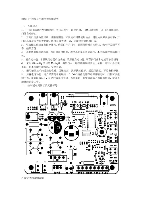
二、控制板布局图以及元件标号:各项定义的详细说明:1. 开关门力调整电位器W1:调整关门反弹力大小,顺时针方向为增大,逆时针方向为减小。
2. 学习灯LRN:遥控器指示灯,用于指示遥控器的工作状态。
3. 学习键LEARN:用于遥控器发射机的学习和删除。
4. 控制/报警端子:外接光电开关和手动开关控制输入/报警输入和输出接口。
从右到左依次为:光电开关接口;墙壁开关接口;报门磁警输入接口;报警门磁输出接口。
接上光电以后PB-IN输入端保持脉冲状态。
当光电开关的光线被阻断时,PB-IN输出高电平,光电开关有效;如果门机处于关门状态,则立刻反弹直到上限位。
墙壁开关:是外接控制门体开、关、停的一个外接代替遥控的开关按键。
报警门磁输入、输出是外接防盗报警的接口,报警门磁输入是外接门磁开关,报警门磁输出是外接报警器,从而实现防盗报警功能。