Deja+Vu+X详细操作手册
欧洲汽车DE型号高压气席高流量舒张器操作手册说明书

SERVICE MANUALF105/200-6031-0/0702/AMA40L HIGH FLOW INSUFFLATORThis manual contains information that is subject to copyright. All rights reserved. This manual should not be photocopied, duplicated on microfilm or otherwise copied or distributed, completely or in part, without the approval of the manufacturer.Some of the parts and equipment referred to in this manual bear registered trademarks but are not identified as such. It should therefore not be assumed that the absence of the trademark indicates that any given designation is not subject to trademark protection. Also, it is not evident whether patents or copyrights exist.Users of ours products should not hesitate to point out to us any errors or unclarities in this manual.Copyright © STRYKER ENDOSCOPYManufacturerSTRYKER ENDOSCOPY5900 Optical CourtSan Jose, CA 95138USATel: +1 800 624 4422Fax: +1 800 729 2917US-2US-3US-4US-5US-6US-7US-82-3-1: Position of High Pressure Unit HPUTurn adjustment screw 1at high-pressure controllerincrease pressure until triggering of the high-pressure valve 3can be clearly heard (hissing sound). Reverse screw 1 until you can no longer hear any hissing sound. The then reached pressure has to be above 4 bar.Reset the adjustment screw to the marked position. AdjustmentUse the adjustment screw 3 of the high-pressure valvefor any adjustments.High Pressure Regulator HPRNOTEThe output value drops with rising temperaturelong operating hours).Relieve pressure of tube at magnetic valve (briefly remove and reconnect tube) until a stable final value of 3.2 bar isreached (±0.6).Remove manometer and reconnect tube.US-9Fig. 2-4-1: F105 Low Pressure Controller Settings2-5Low Pressure Safety Valve LSVClose device exit using a tube clamp (Fig. 2-6-1 , 4).In the service menu, open the LSV Adjust menu option and check the settings.AdjustmentUse the adjustment screw of the low-pressure safety valve for a slight adjustments.2-6Testing Low Pressure Unit for LeaksUS-102Function Test2-8Testing Overpressure Alarm1.Attach a tube and an air-filled syringe to insufflation tubeconnection (Fig. 2-5-1).e the syringe to slowly generate a pressure of 15 mm Hg.3.Slowly increase pressure to 21 mm Hg and press the Start/Stop key.4.An alarm is sounded after approx. 5 seconds andOverpressure is displayed.5.Select gas flow level 2.6.The bleeder (relief) system is activated after approx. 5seconds (time and pressure value can be changed in theuser menu).7.The bleeder system relieves the pressure; alarm andOverpressure warning symbol are turned off.8.Press the Start/Stop key and remove test tools andresources.AdjustmentReplace low-pressure unit.2-9Testing Blockage Alarm1.Connect insufflation tube and close off the end of the tube.2.Press the Start/Stop key.3.An alarm is sounded after approx. 5 seconds andBlockage is displayed. The acoustic warning signal can be deactivated in the user menu.4.Open the insufflation tube connection; the alarm is turnedoff.5.Press the Start/Stop key.AdjustmentReturn device to factory.2-10Testing Gas Heater1.Connect a heater tube to insufflation tube and gas heaterconnection.2.The display depicts HEATING. The tube is being pre-warmed.3.Unplug the gas heater. The display HEATING disappears.4.Remove heater tube.5.Turn off device.AdjustmentReplace HPL board or cable to HPL.Fig. 3-2-4: F105 Low Pressure Controller Settings&RQILUP ZLWK 0(185HTXLUHPHQWVr'HYLFH LQ VHUYLFH PRGH r*DV ERWWOH RSHQr6HWWLQJ DFFRUGLQJ )LJ3UHVV XQWLO GLVSOD\ RQ ULJKWDSSHDUV',63/$<6HUYLFHPHQXRN6HUYLFHPHQX/35 $GMXVW RNr)ROORZ )LJ XVH VFUHZGULYHU WR VHW IURQW SUHVVXUH FRQWUROOHU/3& IURP GLVSOD\ YDOXH $&7 WR '() 0(18 hqw à r r RN$&70,1[[Fig. 3-2-6: LSV Setting&RQILUP ZLWK 0(18r'HYLFH LQ VHUYLFH PRGH r6HWWLQJ DFFRUGLQJ )LJ 'HYLFH H[LW FORVHG3UHVVXQWLO GLVSOD\ RQ ULJKW DSSHDUV',63/$<r)ROORZ )LJ DQG XVH VFUHZGULYHU WR VHW /69 DGMXVWPHQW VFUHZ IURP 0(18 r $FNQRZOHGJH HUURU PHVVDJH ZLWK r &KHFN HUURU PHVVDJH DQG hqw à r r RN$&70,1[[/69 $GMXVW6HUYLFHPHQX/69 $GMXVW RN6HUYLFHPHQX6yy Pss r RNr Ãp qrà $&70,1'()0$;;;/69 $GMXVW4-1-1: Device Rear: Gas Connection PortHigh Pressure Unit Fastening Screws Gas Connection4-1-2: High Pressure Unit ConnectionsHigh Pressure Unit HPUHigh Pressure FuseConnection for Gas TubeHigh Pressure SensorHigh Pressure Sensor ConnectionTemperature Sensor ConnectionReplace elements if malfunctioning and in case determined flow limitation.Open device as described in Chapter 1-7.Remove gas connection (see Fig. 4-1-1) as described inChapter 4-2.Remove gas tube from HPU as well as the electric jumpers (see Fig. 4-1-2).Unscrew the four fastening screws on rear plate andremove HPU.Reverse instructions to install elements.Conduct the following tests after replacing components:CO2 Gas ConnectionSupply ConnectionFlat SW 24Anti-Twist StopSealelements in case of defective, non-sealing flow-reducing filter soiling,is reduced.Use SW 24 adjustable wrench to Unscrew rear plateMake sure O-ring remains in place when removing component.instructions to install elements.stop is properly inserted when4-3-1: Position LPUFlat Cable/Plug-in ConnectionElectrical Plug-in Connection with High PressureTube Connection with HPUComplete LPUSW 7 Nut / Tooth Lock Washer (4x)Connection TubeRemove the connection tube from the LPU 36Unscrew the plug-in connections for the electronic plugs12.Unscrew four fastening nuts 5 at base case ofpneumatics unit; remove the tooth lock washers, and lift out the entire LPU complete with block, valves, and board. Reverse instructions to install elements.Conduct the following tests after replacing components:Calibration according to Chapters 3-2-1 to 3-2-6 andChapter 3-2-8.Position Power PackVoltage Input Cable/Plug-in ConnectionFastening Nuts/Tooth Lock Washers for CoverPower PackFastening Nuts/Tooth Lock Washers for CoverVoltage Output Cable/Plug-in Connection Remove the electrical plug-in connectors 15Use SW 5.5 adjustable wrench to Unscrew four fastening24 on cover and remove cover.Unscrew two bolt screws on front of power pack board and two nuts in rear and lift power pack from case.instructions to install elements.the following tests after replacing components:Use a multimeter to check voltage at input and output ofpower pack.Switch on device and perform function check.Safety test according to Chapter 2-1.Fig. 4-5-1: Position Non-Heating Device PlugBolt Screw for Mass Connection/Potential EqualizationLinePower PackPower Pack Connector Plug(Fig. 4-5-1) Unscrew PE connection 1.Remove plug-in connector at cable of non-heating device plug of power pack 2 by pulling towards top. (Fig. 4-5-2) Unscrew two fastening screws 1at rear plate and remove non-heating device plug by pulling towardsrear.Reverse instructions to install elements.4-5-2: Non-Heating Device Mounting ScrewsNon-Heating Device Mounting Screws Conduct the following test after replacing modules orcomponents:Switch on device and perform function check. Safety test according to Chapter 2-1.4-6-1: Position Panel Board (ON/OFF Key)Plug-in Connector to Basic Module BAM 01Plug-in Connector to I/O Module IOM 01Panel BoardRemove the electrical plug-in connectors 12 Unscrew two nuts and washers 3.Remove board.Reverse instructions to install elements.Conduct the following tests after replacing components:Remote control test, installation check, function test, display.Safety test, Chapter 2-1.4-7-1: Component Boards-/Module ReleaseLocked position-> Press to releaseComponent Board/ModuleReleased position-> Press to lockRemove the electrical plug-in connectors from the component boards/modules.Firmly grasp component board/module and press button to release.Reverse instructions to install elements.Fig. 4-8-1: Position Video Board/LCD1Fastening Nut/Tooth Lock Washer2Plug-in Connector from I/O Module3Video Module DIU4Terminal Screw for Cable from I/O Board5Fastening Nut/Tooth Lock WasherThe video board and the LCD can be removed without first having to disassemble other components. However, access to the video board is much easier if the front panel has been removed (see Chapter 4-12).A SW 5.5 fork wrench/ring wrench and a small screwdriver are required for the removal of the video board.Be careful not to damage any cables or other components when removing the video board.Remove the cable connectors 24.(4x) Unscrew the fastening nuts 15and tooth lock washers at the corners of the video board 3.Watch out for the distance sleeves between video boardand LCD when removing the video board together with the LCD from the bolt screws.Reverse instructions to install elements.Conduct the following test after replacing modules or components:Position Heater BoardConnecting Cable to I/O Module IOMBoard HBNut/Tooth Lock Washer for FasteningNut/Tooth Lock Washer for Fasteningboard can be removed without first havingother components.fastening nuts andtooth lock washers 34.Remove board 2together with the connecting cable from bolt screws by pulling towards rear.Remove cable connector from heater board.instructions to install elements.the following test after replacing modules Heater function test ( Chapter 2-9).4-10-1: Position Insufflation Tube ConnectionFluid Sensor (FLS)Fluid Sensor Electrical ConnectionL-Shaped Adapter from Fluid SensorRemove connecting cables and front panel (see Fig. 4-12). Carefully remove the FLS 1together with the L-shaped adapter 3.Use a SW 19 adjustable wrench to unscrew inner lock nut from gas outlet.Remove locknut and lock washer.Pull gas outlet towards front and remove.instructions to install elements.the following tests after replacing modules components:Leak test according to Chapter 2-5.Safety test, Chapter 2-1.Fluid Sensorif malfunctioning.The electrical connector of the fluid sensor (Fig. 4-10-1, 2) is integrated into the connecting adapter between insufflation tube connection and pneumatic unit. necessary, replace the entire connecting adapter.Remove cable from the cable connector.Detach tube connection as described in Chapter 4-10.instructions to install elements.the following tests after replacing modules components:Leak test according to Chapter 2-5.Safety test according to Chapter 2-1.Fig. 4-12-1: Fastening Front Panel1Mounting Screws2Insufflation Tube Connection3Plug-in Connection4Plug-in Connection5Mounting ScrewsRemove the electrical plug-in connectors 34. Unscrew 2 cross-recessed screws 15on the left andright.Remove tube connection to the insufflation tube connector.Carefully remove front panel by pulling towards front.Detach elements attached to the inside of the front panel. Reverse instructions to install elements.Conduct the following tests after replacing modules or components:Function test of replaced components.Safety test according to Chapter 2-1.5Spare Parts ListArtikelnummer 200-3432-X 200-1057-X41-00096-1X 200-1055-X 200-1054-X 200-0811-X 200-3400-X 200-3399-X 200-3401-X 200-3393-X46-10027-1X 200-4443-X 200-3392-X 200-3397-X 200-3406-X16-00002-1X 200-3409-X 200-3440-X46-00054-1X DescriptionCompl. High Pressure UnitCompl. Power PackNon-Heating Device PlugBasic Board ModuleInput/Output Board ModuleLCD Board / DisplayPanel BoardGas Heater BoardCompl. Pneumatics Unit (Low Pressure Unit) Compl. Set of Insufflator Cables Insufflator Tube SetTube Connection F105 6/8Case CoverFront PanelCompl. Fluid SensorDevice CastorsCompl. Video BoardHermes InterfacePotential Equalization Plug6Calibration Error Messages*To troubleshoot check connections and settings first and then repeat the calibration process before replacing a component or component group.CauseGeneral errorTimeoutGeneral software errorEEprom write errorGeneral gas supply errorGeneral offset calibration errorOffset Low pressure regulator too lowOffset Low pressure sensor too lowOffset Safety pressure sensor too lowOffset Differential pressure sensor too lowOffset High pressure sensor too lowOffset Temperature sensor too lowOffset Current monitoring of high pressure gas heater too low Offset Gas heater too lowOffset Low pressure regulator too highOffset Low pressure sensor too highOffset Safety pressure sensor too highOffset Differential pressure sensor too highOffset High pressure sensor too highOffset Temperature sensor too highOffset Current monitoring of high pressure gas heater too high Offset Gas heater too highGeneral low pressure calibration errorLow pressure - large leakLow pressure - small leakLow pressure intake value too lowLow pressure intake value too highAmplification I - Low pressureAmplification I - Low pressure sensor too high Amplification II - Low pressure sensor too low Amplification II - Low pressure sensor too high Amplification - Safety pressure sensor too lowLow pressure amplification - Safety pressure sensor too high TroubleshootingReplace LPUReplace LPUReplace LPUReplace LPUCheck gas supplyReplace LPUReplace LPUReplace LPUReplace LPUReplace LPUReplace LPUReplace LPUReplace LPUReplace LPUReplace LPUReplace LPUReplace LPUReplace LPUReplace LPUReplace LPUReplace LPUReplace LPUCheck FISCheck manometer connection Check manometer connection Check gas supply, HPU Check gas supply, calibrate LPR Replace LPUReplace LPUReplace LPUReplace LPUReplace LPUReplace LPUE rror Message 01234101112131415161718192021222324252650515253545556575859606Calibration Error Messages* To troubleshoot check connections and settings first and then repeat the calibration process before replacing a component or component group.E rror and Warning Messages 7073747576779091110111130131132133134135136137138139140141142143144CauseGeneral High Pressure Calibration ErrorHigh pressure intake value too lowHigh pressure intake value too highHigh pressure sensor value has changedHigh pressure sensor amplification too lowHigh pressure sensor amplification too highGeneral low pressure regulator calibration errorAdjustment - Low pressure regulator not inrangeLow pressure safety calibration errorAdjustment - Low pressure safety not in rangeFlowFlow resistance too highFlow intake value too lowFlow intake value too highFlow sensor value changedAmplification - Flow sensor too lowAmplification - Flow sensor too highOffset Proportional valve too lowOffset Proportional valve too highHysteresis - Proportional valve too lowHysteresis - Proportional valve too highAmplification - Proportional valve too lowAmplification - Proportional valve too highSticky proportional valveTroubleshootingReplace HPUCheck gas supplyCheck gas supplyCheck gas supplyReplace HPUReplace HPUReplace LPURepeat calibrationCheck flow meter, replace LPURepeat calibrationCheck flow meter, replace LPUCheck flow meter, replace LPUReplace LPUReplace LPUReplace LPUReplace LPUReplace LPUReplace LPUReplace LPUReplace LPUReplace LPUReplace LPUReplace LPUReplace LPU7Technical DataPower Supply100 -240 V~Main Fuse T 3,15 AUSA 3,15 A (slow blow), UL-recocnized220-240 V~Main Fuse T 3,15 A, UL-recocnizedConnection for potential equalizationFrequency50-60 HzMax. Power Consumtion130 /150*WMax. Current 100 V:1250/1400 *mA240 V:540/620* mAProtection Class I, Typ BF, IP41Dimensions Width x Height x Depth273 x 145 x 360 [mm]10,75x5,7x14,2 [inch]Weight Approx. 7 kgOperation Conditions10-40 °C / 50-104°F30-75% rel. air humedityStorage and Transportation Directions-40 - +70 °C /40 - +158°F10-85% rel. air humedity85-100% rel. air humedity (14 days) Manufactured and Tested acc. to EN 60601-1 / IEC 601-1EMV EN 60601-1-2 / IEC 601-1-2CE93/42/ EWGInsufflation medium Medical CO2Maximun output pressure55 mm HgMaximun gas supply pressure80 bar/1160 PSIMinimum gas supply pressure 5 bar/73,3 PSIMeasurement range of gas supply0-50 bar/0-725 PSIMaximun gas flow refer to device data plate located on rear of the device Pressure range1-30 mm HgAccuracy of pressure measurement±5 %Accuracy of gas flow measurement±5 %Accuracy of volume measuremant±10 %Accuracy of gas supply measurement±10 %Conections (optional)Video S-VHS IN/OUTVideo FBAS IN/OUTVideo RGB IN/OUTRS232 Service Interface* with reusable haeting tube8GlossaryTerm ExplanationADC Analog/Digital ConverterBAM Basic ModuleDIU Display UnitDPS Differential Pressure SensorEPx Electrical ConnectionFLS Fluid SensorHIF Hermes InterfaceHPH High Pressure HeaterHTS High Pressure Temperature Sensor HB Heater BoardHPR High Pressure RegulatorHPS High Pressure SensorHPT High Pressure TubeHPU High Pressure UnitHPS High Pressure SensorIFM Interface ModuleIOM Input/Output ModuleKEY Plastic foil keyboardLPT Low Pressure TubeLPR Low Pressure RegulatorLPU Low Pressure UnitLSV Low Pressure Safety ValveMSA Measuring Signal AmplifierMPT Median Pressure TubeMSV Median Pressure Safety Valve OLV Output Line ValvePBU Pneumatic Base UnitPCU Pneumatic Control UnitPMS Pressure Measuring Sensor PRM Pressure Regulator ModulePNB Pneumatic BlockPRV Proportional ValvePSM Power Supply ModuleRCB Remote Control BoardSPS Safety Pressure SensorSRV Service interfaceNTS Nominal Temperatur Sensor VAC Valve ControlsVEV Vent Exit ValveVIM Video Module9IndexSymbole12h Test23AAdjustment9,10,11Authorized service technicians3BBlockage Alarm11CCable Layout Plan6Cabling9Calibration13Certificate3Contamination3EElectronic Boards9Explosion Diagram5 Explosionsdarstellung5FFactory Default24Flow Calibration19,20Flow Volume10Flow-Kalibrierung19Front of the Device7Front Panel31Front Panel and Case9Function Tes7Functional Diagram4GGas Connection26Gas Heater11Glossar36HHeater Board HB30Heater Calibration22High Pressure Calibration17High Pressure Regulator HPR9High Pressure Unit (HPU)9High Pressure Unit for Leaks9High Pressure Unit HPU25High Pressure Valve HPV9HIGH-Pressure Kalibrierung17IInsufflation Tube Connection (Gas Outlet)30 LLiability3Low Pressure Calibration15Low Pressure Regulator LPR10Low Pressure Safety Valve LSV10Low Pressure Unit for Leaks10Low Pressure Unit LPU26LOLPR Calibration18LSV-Calibration21MModules/Boards29NNon-Heating Device Plug27OOffset Calibration14Opening the Device8 Overpressure Alarm11PPanel Board (ON/OFF Key)28 Power Pack27Protection from Germs3RRear of the Device8SSafety Test9Service Menu12TTechnische Daten35Testing High Pressure Unit for Leaks9 Testing Tools and Resources7 Tubing9VVerkabelungsplan6Video Board/LCD2910Maintenance- and ChecklistType of device:: Device no.: Location of use::Maintenance date: Inspected by: Company:I. Safety Test (chap. 2-1)Main fuse Incriptions Mechanical Condition Cleanliness Plug connections PC Boards Front panel and casingII. Function Test (chap. 2)High Pressure Unit HPU Low Pressure Regulator LPR Niederdruckeinheit LPU Flow VolumeWarning overpressure Blockage AlarmGas HeaterIII. RemarksDate SignatureTest RecordDate Result Remarks SignatureReturn formIf you have to return the device, please fill out the card below and mail the manual back with the device.Name of owner:Zip code: City:State/Province:Country:Type of device:Device identification number (see ID marker):Description of defect:US-41 "US-42Address for ServiceSTRYKER EN DOSCOPY5900 Optical CourtSan Jose, CA 95138USATel: +1 800 624 4422Fax: +1 800 729 2917STRYKER AUSTRALIA Pty Ltd50 Broughton RoadArtarmon, NSW 2065AustraliaTel.: +61 2 9415 5100Fax:+61 2 9420 0633STRYKER CHIN A LtdRoom 1710, Kodak House 239 Healthy Street East, North PointHong Kong, ChinaTel.: 852 2814 7463Fax: 852 2873 0210STRYKER GUAN GZHOU - REPRESEN TATIVE OFFICE Room 3007, Jian Li Bao Building410 Dong Feng Zhong RoadGuangzhou, 510620, ChinaTel.:+86 20 8348 6919/6920Fax:+86 20 8348 6921STRYKER SHAN GHAI - REPRESEN TATIVE OFFICE Room 2718-20, Shanghai Central Plaza381 Huai Hai Zhong RoadShanghai 200020, ChinaTel.:+86 21 6391 6887Fax:+86 21 6391 6119STRYKER PACIFIC LtdSuite 2501, Citibank TowerCitibank Plaza, 3 Garden RoadCentralHong Kong, ChinaTel.:+852 2840 4400Fax:+852 2804 6303STRYKER SHEN GYAN G - REPRESEN TATIVE OFFICE Room 501, Block B,Shenglong Int`l Hotel97A Zhongshan Road, Heping DistrictShengyang 110001, ChinaTel.:+86 24 2284 2583Fax:+86 24 2285 5366STRYKER CHEN GDU - REPRESEN TATIVE OFFICE Room B, 26/F., First City Plaza308 Shun Cheng Da JieChengdu, Sichuan Province,ChinaTel.: +86 28 652 8693/7572Fax: +86 28 652 8177STRYKER FAR EAST Inc., THAILAN DA3 Floor, Unit D1, 719 KPN TowerRama 9 Road, BangkapiHauykwang, Bangkok 10360ThailandTel.:+662 717 0551/2Fax:+662 717 0553STRYKER MALAYSIA Sdn. Bhd.No. 55, Lorong Rahim Kajai 13Taman Tun Dr. Ismail60000 Kuala LumpurMalaysiaTel.:+60 3 7725 3650/7725 3651Fax:+60 3 7725 5228STRYKER BEIJIN G - REPRESEN TATIVE OFFICE Room 832, Capital Times SquareNo. 88 West Chang An StreetBeijing 100031, PR ChinaTel.:+86 10 839 131023Fax:+86 10 839 13571STRYKER INDIA Pvt. Ltd.C-5, First Floor,SDA Commercial ComplexNew Dehli - 110016IndiaTel.: +91 11 686 6740Fax:+91 11 696 6020STRYKER SIN GAPORE Pte. Ltd.70 Bendemeer Road#03-02 Hiap Huat HouseSingapore 339940Tel.:+65 293 0119Fax:+65 293 7028STRYKER HOWMEDIA GmbH Gewerbeallee 1845478 Muelheim a.d. RuhrGermanyTel.: +49 208 999 060Fax: +49 208 999 06325STRYKER-OSTEON ICS BVMarinus Van Meelweg 175657 EN EindhovenTheNetherlandsTel.: +31 40 2922 522Fax: +31 40 2922 555STRYKER OSTEON ICS SA-LUGAN OVia della Posta6934 BioggioSwitzerlandTel.: +41 91 610 44 10Fax: +41 91 610 44 70STRYKER FRAN CE S.A. 13, Rue de la PerdixZAC Paris Nord II 93290 Tremblay En FranceTel.: +33 1 4817 5000 Fax: +33 1 4863 8170 STRYKER U.K. Ltd Stryker House Hambridge RoadN ewbury BerkshireRG 14 5EGEngland, United Kingdom Tel.: +44 163 5262400 Fax: +44 163 5580606STRYKER SPAINManual Tovar 3528034 MadridTel.: +3491 728 3500Fax: +3491 358 0748 STRYKER MIDDLE EAST/AFRICA P.O.Box 26589Abu DhabiU.A.E.Tel.: +9712 631 2145Fax: +9712 631 3698Address for ServiceF105/200-6031-0/0702/AMA P/N 1000-400-564。
DejaVuX详细操作手册

déjàvuDéjà Vu X(工作组版)上手指南徐彬(simon_xb@sohu。
com)译(在déjàvu Professional环境下)目录Déjà Vu X(工作组版)的组成 (3)项目 (3)翻译记忆 (4)术语库 (5)SGML/XML过滤器 (5)Déjà Vu工作组版使用教程 (6)创建项目 (6)翻译文件 (14)导出完成的翻译 (22)倍增生产力 (23)预翻译 (26)字数统计和统计数字 (30)Déjà Vu X Workgroup 构成项目Déjà Vu X(工作组版),工作时面对的是项目文件.Déjà Vu 工作组项目是一个具有特殊结构的电脑文件,Déjà Vu 工作组版能够识别、显示、管理该文件,帮助你完成翻译工作.项目包含下列内容:-翻译工作中的所有文本,包括源语文本和翻译文本,二者使用表格的样式呈现。
-左栏显示源语文本, 右栏显示目标语言. 每次只显示一个目标栏.-每个源语句子占一行. 源语文本根据一定的规则被切分为表格单元。
用户可以设定相应的规则.-原始文档的格式和其他信息. 这些不可译信息或者隐藏于句子(表格行)之间,或者是隐藏在控制码中。
项目所使用的源语文件,可以是不同的格式,只要Déjà Vu支持即可(软件所支持的格式请参见用户手册). 这些文件可以是位于电脑的某个文件夹内,或是局域网的其他位置。
表格的行可以以不同的方式显示:-一次一个文件-或是所有的文件一起显示。
两种方式下行都可以以字母顺序排列显示,或是按文档原来的顺序显示(即句子在原文中出现的顺序显示)。
你将进行翻译的工作文件称作Déjà Vu 项目 .dvprj)。
你可以在Déjà Vu 工作组主界面中创建并打开这些文件。
德马格中文操作说明书
液压顶出 后退 / 前进
气阀 1-4 打开
中子 抽芯 / 进芯
自动安全门 打开 / 关闭
Rotary table index bolt move in / move out
模厚调整 增加 / 减小
旋转模板 逆时针 /顺时针
提示 “模厚调整”按钮只针对曲轴式机床。“自动安全门”和“气阀 1-4”按钮只有当这些功 能配置以后才起作用。“Rotary table latches”, Rotary table index bolt” and “旋转模板”应 用于带转转模板的多色注塑 。
Sfu服EnRc务tVio页InC面Egr功oup 能组
Afu报LnAc警tRio功Mn能Sgr组oup
Fig. 2: 功能选择键
1.2 手动功能键
在手动和点动模式下可通过下面的按钮(见Fig. 3 和 Fig. 4)进行相应的操作。 Fig. 3: 手动模具装置功能
模具 打开 / 闭合
Rotary table latches move in / move out
4.4
帮助功能键和专家系统 .......................................................................................................19
5
频幕 ..........................................................................................................20
Pfu程RnOc序tGio功Rn能AgrM组oSup
Process 过Pfu程RnOc控tCio制EnS功gSr能oCu组pONTROL
KIT DE MONTAJE DUAL VOYA E+ 用户手册说明书

MANUAL DEL USUARIO
KIT DE MONTAJE DUAL VOYA E+
Especificaciones Material: aluminio Color: Negro mate Peso: 100g
Contenido del paquete Material del guardabarros delantero: (F-a) 2 x Tornillos M5*21 Material del guardabarros trasero: (R-a) 2 x tornillos M5*10 (R-b) 1 x Juego de abrazaderas M5 (R-c) 1 x tornillos M5*16 (R-d) 1 x arandela 10*9
- Utilice únicamente el juego del portaequipajes y el guardabarros y el material de instalación suministrado.
- No modifique el juego del portaequipajes y el guardabarros de ninguna manera.
- Mediante revisiones periódicas, asegúrese de que todos los tornillos estén apretados, ya que las vibraciones pueden aflojarlos con el paso del tiempo.
activado y en un terreno nivelado. 2. Retire cualquier accesorio que pueda interferir con la instalación o el
西马可-XSE 操作员手册说明书

13
应用程序页面
与系统连接的每个应用程序都显示在面板上。应用程序可以显 示为全页,或与其他面板一起显示在多面板页面中。 所有应用程序页面均可从主页访问。
127 无线连接 127 连接及断开无线热点 128 GoFree 商店 128 GoFree Link 129 将日志文件上载到 Insight Genesis 130 无线设置
132 AIS 132 AIS 目标符号 133 查看有关 AIS 目标的信息
10
目录 | GO XSE 操作员手册
134 呼叫 AIS 船舶 134 AIS SART 136 船舶警报 136 船舶设置
101 回声测深
101 测深仪图像 102 缩放图像 102 在图像上使用光标 103 保存航点 103 查看历史记录 104 设置图像 105 高级选项 106 开始记录日志数据 107 停止记录日志数据
目录 | GO XSE 操作员手册
9
108 查看记录的回声测深数据 108 测深仪视图选项 110 回声测深设置
81 雷达
81 “雷达”面板 82 双雷达 82 雷达叠加 83 雷达操作模式 83 雷达范围 84 在雷达面板上使用光标 84 保存航点 85 雷达盲区 85 调整雷达图像 89 高级雷达选项 90 雷达视图选项 95 EBL/VRM 标记 96 在您船舶周围设置警戒区 97 MARPA 目标 99 记录雷达数据 99 雷达设置
1 工具 选择某一按钮可访问用于执行任务或用于浏览已存储的 信息的对话框。
2 应用程序 选择某一按钮可将应用程序显示为全页面板。按住某一 按钮可显示应用程序的预配置分页选项。
KEPServerEXv4使用说明

K E P S e r v e r E X 用法授权:运行软件---- 在菜单栏HELP 中------- 选择licenseaplugin ---- 在弹出的对话框中选择设备类型----------------------点击license ---- 复制弹出对话框的license ID -------- 在菜单栏HELP 中,选择unlock licenseaplugin------------------在弹出对话框中,复制competer ID ------- 把competer ID 粘贴到licenseaplugin 对话框competer ID 中 --- 复制出现的UNLOCK 号 --------- 粘贴到unlock licenseaplugin 对话框中。
OK!1、new2、+cha nnel,设通讯参数串口、波特率==,后面的几页默认就行3、+device,设地址,设request周期这部分看看说明书,很简单的E 文,有些选项默认即可,用wincc 做实验,有问题再回来改参数这一步有个地方是可以导入变量的,不用手动一个一个加的4、还有如果wincc 与运行这个软件不在一台机器上,要设置DCOM 的,软件里面有说明或者上网查在WINDOWS XP SP系统中使用OPC的DCOM己置方法(Using OPC via DCOM with XP SP2 )大多数OPC Clients和OPC Servers利用DCOM!过网络进行通信。
在XP SP2中,经由DCOI的OPC1信是默认关闭的,本文讨论了当使用XPSP2时重建OPC!信的必要设置方法。
由于OPC使用的回调方法使得OPC Client转变为DCOM server同时使OPC Server转变为一个DCOM client,所以本文中提供的配置方法应在包含有OPC Server和OPC Client 的客户端节点上分别进行设置。
人教版英语9年级 Unit 8 第2课时(A 3a-3c) Deja vu

Listen and analyze the passage
定语从句 Have you ever done something that felt familiar, even
though you knew you hadn’t? This feeling is known as even though引导的让步状语从句 被称为;被认为是
Others even think there could be a link between déjà
vu and parallel universes. However, most scientists say
that déjàvu is just a mix-up in the brain,[making us
déjàvu, a French term meaning “ already seen”.
据说…… It is said that most people have experienced déjàvu at least once in their lives. But why does it happen? People have studied this fascinating question for over a century, and there are now a number of interesting theories about
有趣的理论 déjàvu. Some people believe the familiar scenes of déjàvu must come from past dreams. And some suggest that déjà vu might show we have a hidden power to see the future.
洛雷кс数字高清监控系统用户手册说明书
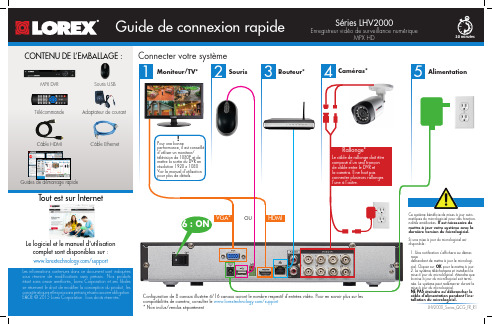
Les informations contenues dans ce document sont indiquées sous réserve de modifications sans préavis. Nos produits étant sans cesse améliorés, Lorex Corporation et ses filiales se réservent le droit de modifier la conception du produit, les caractéristiques et les prix sans préavis et sans aucune ob E&OE © 2015 Lorex Corporation. Tous droits réservés.Le logiciel et le manuel d'utilisation complet sont disponibles sur :/supportCâble HDMIMPX DVR Guides de démarrage rapideAdaptateur de courantSouris USB1Pour une bonneperformance, il est conseillé d'utiliser un moniteur/télévision de 1080P et de mettre la sortie du DVR en résolution 1920 x 1080 Voir le manuel d'utilisation pour plus de détails.!Tout est sur InternetRallonge*Le câble de rallonge doit être composé d’un seul tronçon de câble entre le DVR et la caméra. Il ne faut pas connecter plusieurs rallonges l’une à l’autre.12Cliquer à l’intérieur de la barrepour choisir une heure de lecture.Cliquer suretsélectionner Cliquer sur Général et sélectionner l'onglet heure .Si le système émet un signal sonore au démarrage, le câble Ethernet n'est peut-être pas ) pour lancer simultanément plusieurs canaux.。
- 1、下载文档前请自行甄别文档内容的完整性,平台不提供额外的编辑、内容补充、找答案等附加服务。
- 2、"仅部分预览"的文档,不可在线预览部分如存在完整性等问题,可反馈申请退款(可完整预览的文档不适用该条件!)。
- 3、如文档侵犯您的权益,请联系客服反馈,我们会尽快为您处理(人工客服工作时间:9:00-18:30)。
Deja+Vu+X详细操作手册本教程由站长百科()教程制作组整理使用说明本电子书为PDF格式,为了方便您浏览,我们为电子书制作了书签。
可以用书签格式的导航:1.点击左侧的书签标志,打开书签,点击书签的内容就可以转到对应页面。
2.你也可以利用PDF的搜索功能来快速查找您需要的内容。
本电子书由站长百科教程组制作,虽然是对收集的资料进行整理,但是,教程制作组人员为此也付出了的辛勤的汗水,所以,请勿私自将全部或部分用于商业用途。
转载书中内容请注明出处,本电子书版权归原翻译者所有。
推荐内容:电子书下载 | 站长百科礼品兑换目录Déjà Vu X Workgroup 构成 (2)项目 (2)翻译记忆 (3)术语库 (3)SGML/XML过滤器 (4)Déjà Vu工作组版使用教程 (4)创建项目 (4)翻译文件 (10)导出完成的翻译 (16)倍增生产力 (17)预翻译 (19)字数统计和统计数字 (22)更多电子书 (23)站长百科(/wiki)站长自己的百科全书分享自己的建站知识 WIKI平台与站长一道共建知识库站长百科活动不断论坛发帖赚银币! 参加1美元竞拍更有机会赢2G超大免费空间! 超值好礼等您拿获取更多信息请访问 1Déjà Vu X Workgroup 构成项目Déjà Vu X(工作组版), 工作时面对的是项目文件。
Déjà Vu 工作组项目是一个具有特殊结构的电脑文件,Déjà Vu 工作组版能够识别、显示、管理该文件,帮助你完成翻译工作。
项目包含下列内容:-翻译工作中的所有文本,包括源语文本和翻译文本,二者使用表格的样式呈现。
-左栏显示源语文本, 右栏显示目标语言. 每次只显示一个目标栏.-每个源语句子占一行. 源语文本根据一定的规则被切分为表格单元. 用户可以设定相应的规则。
-原始文档的格式和其他信息. 这些不可译信息或者隐藏于句子(表格行)之间,或者是隐藏在控制码中.项目所使用的源语文件,可以是不同的格式,只要Déjà Vu支持即可( 软件所支持的格式请参见用户手册). 这些文件可以是位于电脑的某个文件夹内,或是局域网的其他位置.表格的行可以以不同的方式显示:-一次一个文件-或是所有的文件一起显示。
两种方式下行都可以以字母顺序排列显示,或是按文档原来的顺序显示(即句子在原文中出现的顺序显示)。
你将进行翻译的工作文件称作 Déjà Vu 项目 .dvprj). 你可以在Déjà Vu 工作组主界面中创建并打开这些文件. 在同一个界面中你也能打开其他格式的文件, 包括Déjà Vu 翻译记忆文件(.dvmdb)、术语数据库文件. 和SGML/XML过滤器(.dvflt).获取更多信息请访问2翻译记忆Déjà Vu 翻译记忆包含多个电脑文件,里面有你添加的成对的源语和目标语对照句子. 每一队句子都包含主题、客户、用户、项目 ID和时间日期戳.翻译记忆内的信息可以是多语种的,可以包含无限多的目标语言.在你使用Déjà Vu 工作组进行项目翻译的时候,翻译记忆会接收发送进来的句子对. 你也可以从外部数据库 (Excel, Access, 文本, TMX, Trados Workbench.),或是通过对齐源语和目标语文件向翻译记忆添加句子对。
翻译记忆可以导出不同的格式.关于翻译记忆的详细信息, 参见创建和维护翻译记忆用户指南.术语库Déjà Vu的术语库是一个电脑文件,里面是由用户添加的源语-目标语词条。
每个词条都有默认的语法信息、定义,以及主题、客户和时间日期戳等. 所有相关信息都是可调整的.术语库中的信息可以是多语言的,可以包括无限多的目标语言.使用Déjà Vu 工作组翻译项目的时候,术语库可以接收用户发送进去的词条。
用户可以可以通过外部数据库 (Excel, Access, 纯文本等.)添加词条。
术语库可以导出为不同的外部文件格式.有关术语库的详细信息, 参见用户指南上的创建和维护术语库数据库。
获取更多信息请访问 3SGML/XML过滤器A Déjà Vu SGML/XML filter allows you to define filters for files tagged using theSGML/XML standard. Unlike other file formats (FrameMaker, Word, Excel, etc.)supported by Déjà Vu X Workgroup, SGML (Standardized General MarkupLanguage) and XML (eXtended Markup Language) are not real file formats; theyare a standard for tagging files, and for defining those tags. Since each customermay use a different set of tags, an SGML/XML filter must be created for eachone.For more detailed information on working with SGML/XML filters, see Creatingand Maintaining SGML/XML Filters in the User’s Guide.Déjà Vu工作组版使用教程安装好Déjà Vu 工作组版之后,就可以开始本教程了.本章会一步一步带领你了解使用Deja Vu翻译的全过程,我们使用的例子是ACME SpeedPrint 720 和SpeedPrint 1440这两个文件。
. 虽然例子中使用的产品规格说明一点趣味性都没有,但是通过翻译这样的文件,你可以更多地了解 Déjà Vu 工作组的特性.组织你的文件开始使用Déjà Vu X(工作组版)之前, 首先要做的事情是组织好你的工作文件,尤其是确定好将源语文件存放在何处. 你可以在你的C盘上,创建一个文件夹用来放置源语文件,并命名为“我的项目”。
你可以使用Windows资源管理器创建文件夹. Place your cursor on the root folder of the C:drive and choose New on the File menu. Then choose Folder and name the folder "My Project."Once you have created the directory, you should copy the example files from the\Samples subdirectory in the Déjà Vu X Workgroup CD. 把SP720.RTF and SP1440.RTF 两个示例文件复制到我的项目文件夹。
打开这两个文件,浏览一下文件的格式,你会看到它们包含了许多格式化信息(包括加粗、斜体,和超级链接). 关闭这两个文件.创建项目项目文件是在 Déjà Vu X(工作组版)主界面里创建的。
使用同样的界面,你可以打开先前创建的项目,或是创建、打开翻译记忆, 术语库和 SGML/XML过滤器.创建项目获取更多信息请访问41 打开Déjà Vu X(工作组版).2 在文件菜单上单击单击新建,或是点击工具栏上的新建按钮.3 双击Project 项目, 或是选择后单击OK确定.4 新建项目向导会弹出.5 单击Next下一步.6 向导提示你创建一个项目.获取更多信息请访问 57 单击创建, 选择保存项目的文件夹(本例中,你将把项目保存在“我的项目”文件夹中),然后输入项目的名称,例如“打印机手册”.8 单击打开.9 单击Next下一步,选择项目的源语和目标语言. 选择目标语的时候,你既可以双击所需语言,也可以单击选择,然后单击Add添加.10 单击下一步选择现有的翻译记忆文件或创建新的.获取更多信息请访问611 对于本例,我们需要创建新的翻译记忆. 单击Create创建.12 给数据库起一个合适的名字,例如,“打印”,然后选择保存数据库的文件夹(本例中我们把数据库保存在“我的项目”文件夹中).13 单击Open打开,并点击下一步,然后选择现有的术语库,或创建新的术语库.14 本例中我们创建新术语库. 单击Create创建.获取更多信息请访问715 给数据库起个合适的名字,例如“打印”,然后选择保存数据库的文件夹数据库(本例中我们把它保存在“我的项目”文件夹中).16 单击Open打开和Next(下一步). 在弹出的对话框中你可以选择需要翻译的文件。
17 单击添加,选择“我的项目” 文件夹, 双击Sp720.RTF.18 单击Next(下一步). 在显示的对话框中,你可以为项目选择客户.获取更多信息请访问819 新建项目向导会显示当前设置.20 如果你想调整设置, 可以单击Back(后退); 不需要调整的话单击Next(下一步). 向导显示导入的进度.在导入过程中, Déjà Vu X(工作组版)会执行下列操作:-过滤文本,将大多数格式代码隐藏起来.-用嵌入代码取代字符格式代码,防止意外删除。
-按照规则将段落分割为句子,这些规则位于选项菜单(更多信息参见用户指南中翻译功能一章的句子划分翻译 ).-创建项目文件,其中源语句子放在一栏,对应另一空白栏的目标语.21 创建过程结束后单击Close“关闭”. Déjà Vu X(工作组版)的主界面右侧的文件浏览器窗格会显示出导入的文件。
.获取更多信息请访问9翻译文件1双击需翻译的文件名. 屏幕显示出如图的布局:注意第二个句子开头的{1}符号. 这就是一个控制码. 控制码里包含了原文件句子中的格式化信息.在本例中,{1} 包含了句子所处的单元格的格式化信息。
大多数情况下,你无需了解控制码包含的内容,只要在翻译的时候保持控制码的相对位置正确即可. 例如,如果某个单词左右都有控制码,我们可以猜想在源语文本中,该单词可能是加粗, 斜体等.2在表格中定位源语句子. 如果你现在不是在文件的开头,可以使用卷滚条移动到开头,或者使用Ctrl+Home组合键跳到文件的开头。