VL900说明书
Veriflo HFR900W型号低硫化氢气调节器说明说明书

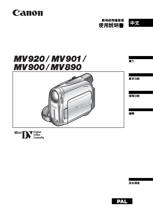
features“VeriClean”, Veriflo’s custom low sulfur high purity 316L Stainless Steel™ enhances electropolishing, welding and corrosion resistance.Internally Electropolished.Connections are welded to the regulator body by autogenous butt welding. This process eliminates small cavities that could create long-term “virtual leaks”and affect the purity of the process gas.The HFR900W was designed to withstand an internal vacuum without distortion of the diaphragm or deterioration of the seat and seal.The low leakage rates of the HFR900W Series eliminates the back diffusion of atmospheric contamination into the system.▼▼▼materials of constructionWettedBody. . . . . . . . . “VeriClean”, Veriflo’s high purity type 316L Stainless Steel Diaphragm. . . . . . . . . . . . . . . 316L Stainless Steel Seat. . . . . . . . . . . . . . . . . . . . . 316L Stainless Steel Seal . . . . . . . . . . . . . . . . . . . Teflon ®and Viton ®or optional Teflon ®and Kalrez ®Non-WettedCap. . . . . . . . . . . . . . . . . . . . . Nickel Plated Brass Knob (Black). . . . . . . . . . . . . . . . . . . . . ABS Plasticoperating conditionsMaximum supply pressure:HFR90(_)WV. . . . . . . . . . . . . . 500 psig (35 barg)HFR90(_)WK . . . . . . . . . . . . . . 200 psig (14 barg)Outlet Pressure. . . . . . . . . . . . . 1-30 psig (2 barg). . . . . . . . . . . . . . . . . . . . . 2-75 psig (5 barg). . . . . . . . . . . . . . . . . . . 5-150 psig (10 barg)Temperature. . . . –40°F to 150°F (–40°C to 66°C)functional performanceDesign burst pressure:90(_)WV . . . . . . . . . . . . . . . 1500 psig (105 barg)90(_)WK. . . . . . . . . . . . . . . . . . 600 psig(41 barg)Design Proof pressure:90(_)WV . . . . . . . . . . . . . . . . . 750 psig (51 barg)90(_)WK . . . . . . . . . . . . . . . . . 300 psig (21 barg)Flow capacity . . . . . . . . . . . . . . . . . . . . . C v = .85. . . . . . . . (SEMI Flow Coefficient Test #F-32-0998)Design Leak Rate:Outboard . . . . . . . . . . . . . . . 2 x 10⁻⁸scc/sec He Inboard. . . . . . . . . . . . . . . . . 2 x 10⁻⁹scc/sec He Supply pressure effect:4 psig per 100 psig(.3 per 7 barg)standard configurations3/8”, 1/2” Tube Stub1/2” Parker Face Seal Fittings1/4”, 1/2” Parker A-Lok Compression FittingsSee Regulator Porting Guide of other available optons.internal volume2.33 cu in (38 cc)surface finishesStandard Ra. . . . . . . . . . . . . . . 15 - 20 micro-inch . . . . . . . . . . . . . . . . . (.38 - .5 micro meter) or lessapproximate weight2.5 lbs. (1.2 kg)Parker Hannifin Corporation’s Veriflo Division presents the HFR900W Regulator. The HFR900W is designed and engineered for the control of high purity, corrosive, toxic, flammable, and inert gases, at a high flow rate and low inlet pressure.▼▼▼▼▼▼▼▼HFR900W SeriesWelded High FlowRegulator▼Catalog:4508LitPN:25000182Revision:A • 10/03BASIC SERIESHFR900=1-30 psig HFR901=2-75 psig HFR902=5-150 psigMATERIALSW =Welded 316L Stainless Steel PORTING 2P = 2 Ports 3P = 3 Ports 4P = 4 Ports 4PB = 4 PortsREGULATOR OUTLET GAUGE 03=0-30 psig 01=0-100 psig 2=0-200 psig X =No GaugeSEAL MATERIALK =Kalrez ® (200 psig max)V =Viton ® (500 psig max)PORT STYLE FS =1/4" Face Seal FS8=1/2" Face Ssal TS =1/4" Tube Stub TS6=3/8" Tube Stub TS8=1/2" Tube Stub 8T =1/2" Compression Fittings *OPTIONAL FEATURES PM =Panel Mount R =Relief Valve HFR900W 4P 03FS8V PMREGULATOR INLET GAUGE4=0-400 psig 6=0-600 psig X =No Gauge6*Compression fittings are welded and inclusive of nuts and ferrules.PORT CONFIGURATION M =Male F =Female I =Internal Face Seal(1/4" Gauge Port Only)FMMF Viton is a registered trademark of DuPont Dow Elastomers.Kalrez and Teflonare registered trademarks of DuPont Company.Pressure Regulator HFR901WOUTLET PRESSURE Range: 2-75 psig5045403510095908580FLOW (slpm) Nitrogen102030405060708090100110120130140150151050Pressure Regulator HFR900WOUTLET PRESSURE (psig)Range: 1-30 psigPressure Regulator HFR900WOUTLET PRESSURE (psig)Range: 1-30 psig30252015FLOW (slpm) NitrogenFLOW (slpm) Nitrogen5.0(127 mm) MAX..69(17.5 mm)1.00(25.4 mm)ø2.38(60.5 mm)ø3.00(76.2 mm)"A"10-32 UNF MOUNTING HOLESHFR900W Series。
Tripp Lite AVR900U 120V 900VA 480W 超级紧凑线性互动UPS说明书

AVR900UAVR Series 120V 900VA 480W Ultra-Compact Line-Interactive UPS with USB portMODEL NUMBER: AVR900U Highlights900VA ultra-compact 120V line interactive UPSCorrects brownouts and98% line mode efficiency rating uses less energy and BTU emissionsBuilt-in grounding lugHot swappable user battery replacementOptional PDUB15 bypass PDU enable hot-swappable UPS replacement with no disruption to connected equipment Space saving, ultra-compact housing with support for wall-mount, desktop or floor placementSpecificationsOUTPUTOutput Volt Amp Capacity (VA)900Output Watt Capacity (Watts)480Nominal Output Voltage(s)110V; 115V; 120VSupportedNominal Voltage Details115v nominal output in battery modeFrequency Compatibility60 HzOutput Voltage Regulation (Line120V (+8%, -21%)Mode)Output Voltage Regulation (Battery115V (+/- 5%)Mode)Output Receptacles(12) 5-15RUPS Output Receptacles (Surge6 UPS outlets, 6 surge-only outletsSuppression Only)Hot-Swap PDU options PDUB15 (2U / 8 5-15R outlets)Output AC Waveform (AC Mode)Sine waveOutput AC Waveform (Battery Mode)PWM sine waveINPUTRated input current (Maximum Load)12ANominal Input Voltage(s) Supported120V ACUPS Input Connection Type5-15P; Right-AngledUPS Input Cord Length (ft.)6UPS Input Cord Length (m) 1.8Recommended Electrical Service15A 120VInput Phase Single-PhaseBATTERYHalf Load Runtime (min.)8.4 min. (240w)DC System Voltage (VDC)12Battery Recharge Rate (Included12 hours (10% to 90%)Batteries)Internal UPS Replacement BatteryRBC51CartridgeBattery Access Battery access doorBattery Replacement Description Hot-swappable, user replaceable batteriesExpandable Runtime NoVOLTAGE REGULATIONVoltage Regulation Description Automatic voltage regulation (AVR) maintains line power operation with an input voltage range of 83 to 147 Overvoltage Correction Input voltages between 129 and 147 are reduced by 12%Undervoltage Correction Input voltages between 83 and 104 are boosted by 14%USER INTERFACE, ALERTS & CONTROLSSwitches Combination switch controls on/off power status and self-test operationAudible Alarm Audible alarm indicates power-failure and overload statusLED Indicators 2 LEDs indicate power status and overload/check battery statusSURGE / NOISE SUPPRESSIONUPS AC Suppression Joule Rating420UPS AC Suppression ResponseInstantaneousTimeUPS Dataline Suppression 1 line TEL/DSL (1 in / 2 out)EMI / RFI AC Noise Suppression YesPHYSICALInstallation Form Factors SupportedTower; Ultra-compact desktopwith Included AccessoriesPrimary Form Factor DesktopUPS Power Module Dimensions4 x 12 x 7(hwd, in.)UPS Power Module Dimensions10.16 x 30.48 x 17.78(hwd, cm)UPS Power Module Weight (lbs.)15.3UPS Power Module Weight (kg) 6.94UPS Shipping Dimensions (hwd / in.) 5.5 x 14.5 x 9.8UPS Shipping Dimensions (hwd /13.97 x 36.83 x 24.89cm)Shipping Weight (lbs.)16.3Shipping Weight (kg)7.4UPS Housing Material ABSPrimary UPS Height (mm)102Primary UPS Width (mm)305Primary UPS Depth (mm)178Shipping Height (mm)140Shipping Width (mm)368Shipping Depth (mm)249ENVIRONMENTALOperating Temperature Range+32 to +104 degrees Fahrenheit / 0 to +40 degrees CelsiusStorage Temperature Range+5 to +122 degrees Fahrenheit / -15 to +50 degrees CelsiusRelative Humidity0 to 95%, non-condensingAC Mode BTU / Hr. (Full Load)27Battery Mode BTU / Hr. (Full Load)384AC Mode Efficiency Rating (100%98%Load)COMMUNICATIONSCommunications Interface USB (HID enabled)PowerAlert Software For local monitoring via the UPS’s built-in communication ports, download PowerAlert Local software at/poweralertCommunications Cable USB interface cable includedWatchDog Compatibility Supports Watchdog application, OS and hard-reboot restart options for remote applicationsNetwork UPS Tools Compatibility NUT compatible. See the full list of Tripp Lite NUT compatible UPS systems at/stable-hcl.html?manufacturer=Tripp LiteLINE / BATTERY TRANSFERTransfer Time 4 milliseconds (AC to battery) / 1 millisecond (Battery to AC)Low Voltage Transfer to Battery83Power (Setpoint)High Voltage Transfer to Battery147Power (Setpoint)SPECIAL FEATURESCold Start (Startup in Battery ModeCold-start operation supportedDuring a Power Failure)High Availability UPS Features Hot swappable batteriesGreen Energy-Saving Features Greater than 95% efficiency - GREEN UPSCERTIFICATIONSUPS Certifications Tested to UL1778 (USA); Tested to CSA (Canada); Tested to NOM (Mexico); Meets FCC Part 15 Category B (EMI)WARRANTYProduct Warranty Period (U.S. &3-year limited warrantyCanada)Product Warranty Period (Latin3-year limited warrantyAmerica)Product Warranty Period2-year limited warranty(International)Product Warranty Period (Mexico)3-year limited warrantyConnected Equipment Insurance$100,000 Ultimate Lifetime Insurance(U.S., Canada & Puerto Rico)© 2017 Tripp Lite. All rights reserved. All product and company names are trademarks or registered trademarks of their respective holders. Use of them does not imply any affiliation with or endorsement by them. Tripp Lite has a policy of continuous improvement. Specifications are subject to change without notice. Tripp Lite uses primary and third-party agencies to test its products for compliance with standards. See a list of Tripp Lite's testing agencies:https:///products/product-certification-agenciesAVR900U。
洛雷安记录器NR900XCL用户手册说明书

Once you have recorded your Device ID, you may proceed to set up remote access with the mobile app (see Step 2A) and/or client software for PC and Mac (see Step 2B).
NR900XCL Series
Before You Start:
• This guide is for users who wish to view their security system remotely using mobile apps. If you plan to only view and configure the system locally, you may skip this guide.
• Ensure your recorder is up-to-date with the latest firmware version. • Please note that the following minimum upload speeds are required
for remote video streaming: • 5 Mbps for 4K video. • 3.5 Mbps for lower resolutions. Up to 3 devices may connect to the system at tting
If you are having trouble connecting, try the following:
• Restart the recorder by disconnecting the power adapter, then reconnecting it.
DV900系列安全DVR设备快速安装指南说明书

Copyright © 2019 Lorex CorporationAs our products are subject to continuous improvement, Lorex reserves the right to modify product design, specifications and prices, without notice and without incurring any obligation. E&OE. All rights reserved.Once you have completed the physical setup of your recorder, follow the steps below to configure essential system settings.Now that you have set up your recorder, see the following reference sections to learn more about using your system.STEP 2: Firmware UpdateThis system features automatic firmware upgrades for enhanced functionality. It is required to upgrade your system to the latest firmware version.To upgrade firmware:1. After startup, a notification will appear asking you to upgrade the firmware if a newer version is available. Click OK to upgrade.2. The system will download and install the firmware upgrade. Wait for the firmware update to complete. The system may restart during the firmware upgrade process.IMPORTANT: Do not power off the recorder or disconnect the power cable during firmware installation.ClickClick General to instantly a b c1. LEFT-CLICK:• During split-screen display mode:to view it in full-screen. Click again to return to the split-screen display mode.• While navigating menus:2. RIGHT-CLICK:• During live view: Right-click anywhere on the screen to open the Quick Menu.• While navigating menus: 3. SCROLL WHEEL:• During live view: Use the scroll wheel to zoom in / out. NOTE: In live view, hover the mouse cursor over the top of the screen to open the Navigation Bar. Move the mouse cursor away from the top of the screen to close the Navigation Bar.To quickly open a window that displays vital system information such as device ID, model number, firmware version, and IP address:• P ress the ENTER button on the front panel.OR• R ight-click to open the Quick Menu and click Info . If prompted, enter the system user name (default: admin ) and your new, secure password.b acdefgh iReference: Using the MouseReference: Quick Access to System Informationchannels you would like to playback. Click the display options () to playback multiple channels ba cBack up recordings from the hard drive to a USB flash drive (not included).Insert a USB flash drive (not included) into a free USB port on the recorder.Main Menu .Log in using the system user name (default: admin ) and your new, secure password.ClickConfigure the following:ab c defSTEP 4: Configuring Deterrence Settings1. In live view, right-click and click Main Menu .2. Log in using the system user name (default:admin ) and your new, secure password.3. Clickand select Setting .4. Click Event > Motion > Deterrence(see Figure 1).5. Select the channel of the deterrence camera toconfigure next to Camera .6. Click the Enable checkbox to enable automaticwarning light deterrence.7. Click Setup next to Area to set the active areafor automatic deterrence:To configure automatic deterrence using DVR:Set preferences for the automatic warning light triggering on compatible Lorex deterrence cameras. For a complete list of compatible deterrence cameras, see /compatibility .To activate deterrence features manually:Figure 1: Deterrence TabFigure 2: Deterrence Active Area Example10. Click Apply to save changes.•Press and hold ESC on the front panel for 5 seconds. Warning lights and sirens will be activated for all connected deterrence cameras.Press and hold for 5 seconds.•From live display, hover near the top of a channel to reveal the Mini Menu. Click to activate warning light, or clickto activate siren.8. Click Setup next to Schedule to set a scheduleduring which automatic deterrence will be used:• The camera image appears with a grid of green boxes over top. The green area is the active area for deterrence. • Click or click-and-drag to add / remove boxes from the active area.• In Figure 2, only motion around the doorway will trigger warning light.• Right-click when finished.• The default schedule is active during the night, between 5pm and 7am. • Right-click when finished.9. Click Warning Light to set preferences for the warning light:• Enter a time for the white light to be active up to 30 seconds.• Select Warning Light for sustained light or Strobe for a flashing light. • Click OK to save and exit.。
胜利仪器 VICTOR 9000A蓝牙版高低压钳形电流表 说明书

目录注意 (1)一.简介 (2)二.电气符号 (2)三.主要技术参数 (2)四.技术规格 (3)五.结构 (4)六.液晶显示 (5)1.液晶显示屏 (5)2.特殊符号说明 (5)3.显示示例 (5)七.操作方法 (6)(一)检测仪操作 (6)1.开关机 (6)2.通常测试 (7)3.PEAK测试 (8)4.蓝牙测试 (9)5.数据保持 (9)6.数据存储 (9)7.数据查阅 (9)8.数据清除 (9)(二)蓝牙软件操作 (10)1.软件介绍 (10)2.APP软件安装 (10)3.软件使用 (10)4.软件卸载 (11)九.装箱单 (11)注意感谢您购买了本公司的VICTOR9000A蓝牙版高低压钳形电流表,为了更好地使用本产品,请一定:——详细阅读本用户手册,操作者必须完全理解手册说明并能熟练操作本仪表后才能进行现场测试。
——严格遵守本手册所列出的安全规则及注意事项。
◆任何情况下,使用本仪表应特别注意安全,尤其测量超过AC100V及以上电压线路的时候。
◆若被测线路电压超过600V必须连接绝缘杆使用。
◆由于高压线路很危险,操作者必须经严格培训并获得国家相关高压操作认证才能使用本仪表进行现场测试。
◆严禁用本仪表测试电压超过110kV的裸导线或汇流母线。
◆注意本仪表面板及背板的标贴文字及符号。
◆请勿于高温潮湿,有结露的场所及日光直射下长时间放置和存放仪表。
◆更换电池,请注意电池极性,长时间不用本仪表,请取出电池。
◆拆卸、维修本仪表,必须由有授权资格的人员操作。
◆若本仪表的钳头及其他部件有损伤,请禁止使用。
◆避免冲击钳头,定期保养本仪表,不能用腐蚀剂或粗糙物清洁,须用软布(如眼镜布),沾清洁防锈除湿类的润滑剂(如WD-40),轻轻擦拭仪表钳头即可。
◆由于本仪表原因,继续使用会带来危险时,应立即停止使用,并马上封存,◆◆操作。
◆建议本仪表每年至少进行一次绝缘强度测试(AC110kV/rms5节绝缘杆完全连接,两端之间)。
上海沃陆变频器VL600型变频器说明书

图 2-2 铭牌 AC 表示交流电源输入。 3PH 表示三相输入,380V、50/60Hz 表示额定输入电压和频率。 3PH 表示三相输出,2.2KW、6.5A 表示变频器额定功率和额定输出电流,0~380V 表示变频器输 出电压范围。 0.50~400.0Hz 表示输出频率范围。
3
VL600 高性能矢量变频器
~220(单相)
15
A1
3.7
VL600S0037P-B
~220(单相)
15
A1
3.7
VL600T0015G-B
~380(三相)
2.5
A1
0.75
VL600T0015P-B
~380(三相)
2.5
A1
0.75
VL600T0015G-B
~380(三相)
3.8
A1
1.5
VL600T0015P-B
~380(三相)
注意!
在对变频器进行操作之前,请您仔细阅读本手册。 变频器的存放、安装应避开强振动、强腐蚀、高粉尘、高温、高湿的环境。 应定期检查变频器输入输出接线是否正确及设备其它电线是否老化。 电机绝缘强度要在安装、运行前进行检查。 电机经常低速运转工作时,要对电机采取额外冷却措施。 有频繁起动场合和能量回馈时,要采用制动电阻或制动单元,防止频繁过压或过流。
VL600T0150G-B
~380(三相)
32.0
B1
15
VL600T0150P-B
~380(三相)
32.0
A3
15
VL600T0185G
~380(三相)
37.0
B1
18.5
4
VL600 高性能矢量变频器
Canon MV920 MV910 MV900 MV890 数码视频摄像机 说明书
進階功能
選單和設定.....................................................................................................33 攝像
使用攝像程式 .................................................................................................36 手動調整曝光 .................................................................................................40 手動調整對焦 .................................................................................................41 設定白平衡.....................................................................................................43 選擇影像效果 .................................................................................................44 設定快門速度 .................................................................................................45 使用自拍 ........................................................................................................47 更改記錄模式 (SP/LP) ...................................................................................48 錄音 ...............................................................................................................49 使用數碼效果 .................................................................................................51 寬螢幕電視攝像 (16:9) ...................................................................................54 播放 放大影像 ........................................................................................................55 顯示數據碼.....................................................................................................56 結尾搜索 ........................................................................................................57 播放加錄聲音的磁帶 ......................................................................................58 其他功能 更改顯示語言 .................................................................................................59 其他攝像機設定 .............................................................................................60
DLINK DWL_900AP+ 说明书
无线五合一极品!D LINK DWL 900AP+ 集合无线AP+免驱动无线网卡+无线网桥+多点无线桥接器+万能无线中继器DWL 900AP+具有IEEE802.1x认证、64/128/152位WEP加密、隐藏无线SSID、MAC地址过滤等安全功能。
另外,还具有一对一或多台接入点相互通信的无线桥接功能,具有可根据信号状况自动切换所连接的接入点的漫游功能。
DWL 900AP+性能十分强劲DWL 900AP+支持很多种无线工作模式1:Access Point(纯AP模式)工作在纯AP接入点模式,和普通的AP是一样的,支持802.11b 11MBps或802.11b+ 22MBps的无线网卡接入。
(AP模式可以比Linksys的WET11的点对点模式接多很多个无线客户端,最多达250个)2:Wireless Client(网桥模式)跟Linksys的WET11和D LINK的DWL 810+一样,工作在可以跟任何AP 桥接的网桥模式。
用Site Survey(信号搜索)把对方AP或无线路由的SSID搜索出来,然后连接上去,就是这么简单!(工作在这个模式DWL 900AP+就不会再发射信号出来了,只会接收其他AP或无线路由的无线信号然后把无线信号转成有线信号,就象是一个用LAN口无需驱动的无线网卡一样)(无线网桥模式,适用卫星共享,XBOX PS2接入无线网络或当免驱动无线网卡给台式机使用)3:Wireless Bridge(AP到AP无线桥接)支持两个DWL 900AP+用无线桥接模式来连通两个不同的局域网,设置桥接模式只要将对方AP的MAC码填进自己AP的Bridge项就可以了,这个模式不会再发射无线信号给其他的无线客户接收。
(适合两栋建筑物之间无线通讯使用)4:Multi point Bridge(多AP桥接)支持两个以上的DWL 900AP+无线桥接,将放在中心位置的DWL 900AP+选Multiple Bridge(多AP桥接)然后其他DWL 900AP+统一将中心位置的DWL 900AP+的MAC码填进自己的Bridge项就可以。
- 1、下载文档前请自行甄别文档内容的完整性,平台不提供额外的编辑、内容补充、找答案等附加服务。
- 2、"仅部分预览"的文档,不可在线预览部分如存在完整性等问题,可反馈申请退款(可完整预览的文档不适用该条件!)。
- 3、如文档侵犯您的权益,请联系客服反馈,我们会尽快为您处理(人工客服工作时间:9:00-18:30)。
感谢您选用沃陆变频器!同时,你将享受到我们为您提供的全面、真诚的服务!VL900简易型变频器是高品质、多功能变频器。
该系列变频器能够在多种场合满足您的需求。
本手册为用户提供安装调试、参数设定、操作使用、故障诊断及日常维护的有关注意事项,在安装、使用前请仔细阅读,正确操作。
本手册随变频器一起提供,并请妥善保管,以备以后查阅和维护使用。
目录一,安全使用…………………………………1-2页二,产品简介…………………………………3-6页三,安装配线…………………………………7-17页四,运行操作说明……………………………18-22页五功能参数表………………………………23-41页六,详细功能说明……………………………42-100页七,故障诊断及异常处理……………………101-105页八,保养和维护………………………………106-107页I♦变频器的存放、安装应避开强振动、强腐蚀、高粉尘、高温、高湿的环境。
♦应定期检查变频器输入输出接线是否正确及设备其它电线是否老化。
♦电机绝缘强度要在安装、运行前进行检查。
♦电机经常低速运转工作时,要对电机采取额外冷却措施。
有频繁起动场合和能量回馈时,要采用制动电阻或制动单元,防频繁过压或过流。
12♦ 不要在变频器输出端连接可变电阻器和电容以试图提高功率因数。
不要在变频器输出与电机之间安装断路器,如果必须安装,则要保证断路器仅在变频器输出电流为零时动作。
♦ VL900型变频器的防护等级为IP20。
♦变频器使用1~3个月后,建议对内部器件和散热器进行清洁处理。
如长时间不用,应间隔一定时间(建议一个月)给变频器通电一次。
阅读提示:危险!会引起人身伤亡和财产损失的不正确操作与安装,不正确的使用产品!警告!会引起人身伤害和财产损失的不正确操作与 安装,不正确的使用产品!注意!会影响变频器性能的不正确操作3二:产品简介2.1型号及铭牌产品型号意义为(以三相2.2KW 带内置制动单元的变频器为例):A-不带制动 B-带制动系列代号:G :通用型;P :水泵型功率等级:0022:2.2KW电压等级 :S :单相/三相220V品系列代码图2-1VL900型系列变频器的铭牌如图2-2所示(以三相输入、2.2KW 变频器为例)。
上海沃陆电气有限公司制造商:输出:输入:9.6输出电流:2.2功率:型号:沃陆变频器图2-2 铭牌AC 表示交流电源输入。
3PH 表示三相输入,220V 、50/60Hz 表示额定输入电压和频率。
3PH 表示三相输出,2.2KW 、9.6A 表示变频器额定功率和额定输出电流,0~220V 表示变频器输出电压范围。
0.50~400.0Hz 表示输出频率范围。
2.2产品一览表VL900型变频器的功率范围为0.4~7.5KW,主要信息资料见表2-1。
变频器外形尺寸及安装尺寸见表3-2。
表2-1 VL900型产品一览表456三、安装与配线3.1安装安装方向与空间为了利于变频器散热,要将变频器安装在垂直方向(如图3-1所示),并保证周围的通风空间,表3-1给出了变频器安装的间隙尺寸(推荐值)。
表3-1 间隙尺寸安装环境♦无雨淋、水滴、蒸汽、粉尘及油性灰尘;无腐蚀、易燃性气体、液体;无金属微粒或金属粉末等。
♦环境温度在-10℃~+50℃范围内。
♦环境相对湿度必须在90%以下,且无水珠凝结现象。
♦无强电磁干扰。
♦振动强度在0.5g(加速度)以下。
♦变频器若安装在控制柜内,应保证控制柜内与外界通风良好。
7外形尺寸及安装尺寸表3-2VL900型产品尺寸一览表图3-2 尺寸代码示意图配线标准配线图控制回路配线应与主回路配线相互分开,不可置于同一线路管槽中,以避免可能引起的干扰。
控制配线应选用带屏蔽层的多芯线,导线截面积宜选0.3~0.5mm2,信号线不宜过长。
变频器主回路和控制回路配线方式如下图所示:图3-3变频器标准配线图。
说明:制动电阻与制动单元均为选配件,其选配标准见附录89配线图3-3485-485++10输出电机接地接制动电阻故障继电器输出模拟输出0-10开路集电极输出标准接口输入电源2200-100-10模拟电流0-20模拟电压0-10编程端子五编程端子四编程端子三编程端子二编程端子一 电位器选用:3-10K 2W 以上 485-485++10输出电机接地接制动电阻故障继电器输出模拟输出0-10开路集电极输出标准接口输入电源2200-10模拟电流0-20模拟电压0-10编程端子五编程端子四编程端子三编程端子二编程端子一1)功率端子:不同机型的功率端子结构如下图所示:1) 为三相0.4~7.5KW 变频器主回路端子结构示意图;表3-3主回路端子说明2)控制端子:表3-4跳线开关功能控制板端子的说明(1) J1端子功能说明如表3-6表3-5 控制板J1端子功能10(2) 控制回路端子,排列如下:上图为控制端子图3-4控制板端子排列顺序图 (3)J1端子功能说明如表3-7所表3-6控制板J1端子功能表11注意:跳线端子JP1的下两个点短接表示选择AI2为电流输入(0-20mA),这也是变频器的默认设置;如果有需要输入电压的(0-10V),请将JP1的上两个点短接;注意中间的点为公共点。
跳线端子JP2的上两个点短接表示选择AO1输出为为电流输出(4-20mA);如果下两个点短接那么是电压输出(0-10V),这也是变频器的默认设置。
1213(1) AI1端子接受模拟电压信号输入,接线方式如下:(2) AI2端子接受模拟信号输入,跳线选择输入电压(0~10V)和输入电流(4~20mA),接线方式如下:图3-6 AI2端子配线图 (3) 模拟输出端子AO1的配线模拟量输出端子AO1外接模拟表可指示多种物理量,跳线选择输出电流(4~20mA)和电压(0~10V)。
端子配线方式如图3-9。
图提示:(1) 使用模拟输入时,可在AI1与GND 或AI2与GND 之间安装滤波电容或共模电感。
(2) 模拟输入、输出信号容易受到外部干扰,配线时必须使用屏蔽电缆,并良好接地,配线长度应尽可能短。
+10V AI1VL9000~10V图3-5 AI1端子配线图JP1+ ―10V AI2 GNDPEAI2电压VIAI2电流 屏蔽线近端接地0~10V或4~20mAJP1 V I模拟AO1 GN变频器IVI VJP2 JP2通讯端子的配线变频器提供给用户的通信接口为标准的RS485通讯。
以下几种配线方法,可以组成单主单从或单主多从的控制系统。
利用上位机(PC机或PLC控制器)软件可实现对工控系统中变频器的实时监控,实现远程如图3-12所示,也可以其中一台变频器作主机,其它变频器作从机,如图3-13所示。
随着连接台数的增加,通讯系统越容易受到干扰,建议按如下方式接线:14图3-9 PLC与变频器多机通信时的接线图(变频器、电机全部良好接地)图3-10 变频器多机通信时的接线图(变频器、电机全部良好接地)15如果采用以上配线仍不能正常通讯,可尝试采取以下措施:(1) 将PLC(或上位机)单独供电或对其电源加以隔离。
(2) 通讯线上使用磁环;适当降低变频器载波频率。
符合EMC要求的安装指导变频器的输出为PWM波,它在工作时会产生一定的电磁噪声,为了减少变频器对外界的干扰,本节内容从噪声抑制、现场配线、接地、漏电流、电源滤波器的使用等几个方面介绍了变频器EMC的安装方法。
3.2.5 噪声的抑制(1) 噪声的类型变频器工作产生的噪声,可能会对附近的仪器设备产生影响,影响程度与变频器控制系统、设备的抗噪声干扰能力、接线环境,安全距离及接地方法等多种因素有关,噪声的类型包括:静电感应、电路传播、空间传播、电磁感应等路径④路径⑤路径⑥1617(2) 抑制噪声的基本对策现场配线与接地(1) 变频器到电动机的线缆(U 、V 、W 避免与电源线(R 、T 端子输入线)应保持30厘米以上的距离。
(2) 变频器输出U 、V 、W 端子三根电机线尽量置于金属管或金属布线槽内。
(3) 控制信号线应采用屏蔽电缆,屏蔽层与变频器PE 端相连,靠近变频器侧单端接地。
(4) 变频器PE 端接地电缆不得借用其它设备接地线,必须直接与接地板相连。
(5) 控制信号线不能与强电电缆(R 、T 与U 、V 、W)平行近距离布线,不能捆扎在一起,保持20~60厘米(与强电电流大小有关)以上的距离。
如果要相交,则应相互垂直穿越,如图3-16所示。
(6) 控制信号和传感器等弱电接地线必须与强电接地线分别独立接地。
(7) 禁止在变频器电源输入端(R 、T)上连接其它设备。
图3-11VL900简易型变频器四、运行和操作说明4.0 键盘的操作与使用操作键盘是变频器接受命令、显示参数的主要单元,见下图所示:19LED 数码管及指示灯变频器LED操作面板上设有五位8段LED 数码管、3个单位指示灯、2个状态指示灯。
如图1所示,数码管可显示变频器的监控码、功能码、故障代码等。
三个单位指示灯可组合为七种单位指示。
两个状态指示灯分别为正反转和告警状态指示。
指示灯说明如下:LED数码显示及单位指示灯组合:2021功能参数的设置方法本变频器的功能参数体系包括16组功能码:F0~F9、FA 、FB 、和监控码d 组。
每个功能组内包括若干功能码。
功能码采用(功能码组号+功能码号)的方式标识,如“F5.08”表示为第5组功能的第8号功能码。
LED 键盘显示单元的菜单结构:通过LED 键盘显示单元设定功能码时,功能组号对应一级菜单,功能码号对应二级菜单,功能码数据对应三级菜单。
功能码设定实例:例1:将运行频率数字设定由50Hz 修改为40Hz(F0-03由50.00Hz 改为40.00Hz)1)按PRG 键进入编程状态,LED 数码管显示功能参数F0-00,闪烁位停留在个位.2)键,可以看到闪烁位在功能项的百位、十位、个位移动, 键将闪烁位停留在个位。
3 键将个位的“0”改为“3”。
LED 数码管显示F0.03。
4)按Enter 键,将会看到F0.03对应的数据(50.00),同时,其单位频率对应的发光二极管(Hz)亮。
5) 按5”40.00。
6)按 Enter 键,保存F0.03的值并自动显示下一个功能码(F0.04)。
7)按PRG 键,退出编程状态。
例2:查看监控参数项d-02(输出电流)法一:1) 按PRG键进入编程状态,LED数码管显示功能参数F0.00,再按一次PRG键,数码管显示功能参数d-00直到监控码项显示d-02。
2) 按Enter键,将会看到d-02对应的数据,同时,其单位“安培”对应的发光二极管(A)亮。
3)按PRG键,退出编程状态。
法二:1)LED数码管先显示监控码d-00,d-02监控码及其具体数据。