西门子安全继电器3TK2807
西门子安全继电器-SIRIUS 3TK3安全继电器模块

√ √ -
√ √ √-√17/4技术规格 类型 尺寸 (宽 x 高 x 深)
SIRIUS 3RK3 安全继电器模块
通用数据
主模块
扩展模块 4/8F-DI
2/4 F-DI 2/4 F-DI 4/8 F-RO 1/2 F-RO 2F-DO
4 F-DO 8 DI
8 DO
接口模块
诊断模块
• 螺丝端子 • 弹簧端子
器
与
或
AAAAAAAA&S&&&&&SSSSS&S&SAA-A-------IIIIIII&SSI&S---III
√ √
√ √
输出功能
标准输出
异或
√
√
安全输出
与非
√
√
AS-i 输出功能
√ 提供
- 不提供
状态功能 元件状态
符号
MSS
MSS
基本型 增强型
√
√
√
√
√
√
√
√
√
√
√
√
√
√
√
√
√
√
√
√
√
√
√
√
AAAAAAAAQQQQSQSSSSSSSAAAAAA-AAA-------AQQQQIQQQIIIIIQIQSSSSISSSQSSS----------IIIIIIIIII
- 双通道 重量
1
克
300
-
-
2
-
160
160
160
400
4
-
-
-
-
135 125 160 270
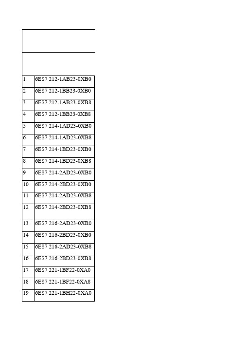
西门子选型手册

西门子选型手册1 6ES7 212-1AB23-0XB0 CPU(8I/6O)晶体管输出2 6ES7 212-1BB23-0XB0 CPU (8I/6O)继电器输出3 6ES7 212-1AB23-0XB8 CPU(8I/6O)晶体管输出 CN4 6ES7 212-1BB23-0XB8 CPU (8I/6O)继电器输出 CN5 6ES7 214-1AD23-0XB0 CPU(14I/10O)晶体管输出6 6ES7 214-1AD23-0XB8 CPU(14I/10O)晶体管输出 CN7 6ES7 214-1BD23-0XB0 CPU(14I/10O)继电器输出8 6ES7 214-1BD23-0XB8 CPU(14I/10O)继电器输出 CN9 6ES7 214-2AD23-0XB0 CPU224XP(14DI/10DO,2AI,1AO)晶体管输出10 6ES7 214-2BD23-0XB0 CPU224XP (14DI/10DO,2AI,1AO)继电器输出11 6ES7 214-2AD23-0XB8 CPU224XP (14DI/10DO,2AI,1AO)晶体管输出12 6ES7 214-2BD23-0XB8 CPU224XP (14DI/10DO,2AI,1AO)继电器输出13 6ES7 216-2AD23-0XB0 CPU ( 24I/16O ) 晶体管输出14 6ES7 216-2BD23-0XB0 CPU(24I/16O)继电器输出15 6ES7 216-2AD23-0XB8 CPU ( 24I/16O ) 晶体管输出 CN16 6ES7 216-2BD23-0XB8 CPU(24I/16O)继电器输出 CN17 6ES7 221-1BF22-0XA0 8点24VDC输入18 6ES7 221-1BF22-0XA8 8点24VDC输入 CN19 6ES7 221-1BH22-0XA0 16点24VDC输入20 6ES7 221-1BH22-0XA8 16点24VDC输入 CN21 6ES7 222-1HF22-0XA0 8点继电器输出22 6ES7 222-1HF22-0XA8 8点继电器输出 CN23 6ES7 222-1BF22-0XA0 8点24VDC输出24 6ES7 222-1BF22-0XA8 8点24VDC输出 CN25 6ES7 223-1PH22-0XA0 8入8出模块继电器输出26 6ES7 223-1PH22-0XA8 8入8出模块继电器输出 CN27 6ES7 223-1PL22-0XA0 16入16出模块继电器输出28 6ES7 223-1PL22-0XA8 16入16出模块继电器输出 CN29 6ES7 223-1HF22-0XA0 4入4出模块继电器输出30 6ES7 223-1HF22-0XA8 4入4出模块继电器输出 CN31 6ES7 223-1BF22-0XA0 4入4出24VDC32 6ES7 223-1BF22-0XA8 4入4出24VDC CN33 6ES7 223-1BH22-0XA0 8入8出24VDC34 6ES7 223-1BH22-0XA8 8入8出24VDC CN35 6ES7 223-1BL22-0XA0 16入16出24VDC36 6ES7 223-1BL22-0XA8 16入16出24VDC CN37 6ES7 231-0HC22-0XA0 4入模拟量模块38 6ES7 231-0HC22-0XA8 4入模拟量模块 CN39 6ES7 235-0KD22-0XA0 4入1出模拟量模块40 6ES7 235-0KD22-0XA8 4入1出模拟量模块 CN41 6ES7 232-0HB22-0XA0 2出模拟量模块42 6ES7 232-0HB22-0XA8 2出模拟量模块 CN43 6ES7 277-0AA22-0XA0 PROFIBUS-DP模块44 6ES7 272-0AA30-0YA0 TD 200显示设定单元45 6ES7 901-3CB30-0XA0 计算机编程电缆及软件46 6ES7 291-8GF23-0XA0 EEPROM 64K47 6ES7 291-8BA20-0XA0 电池48 6ES7 290-6AA20-0XA0 扩展转接电缆 0.8米49 6ES7 231-7PD22-0XA0 4路热电耦模块50 6ES7 231-7PD22-0XA8 4路热电耦模块 CN51 6ES7 231-7PB22-0XA0 2路热电阻模块52 6ES7 231-7PB22-0XA8 2路热电阻模块 CN53 6GK7243-1EX00-0XE0 以太网通讯卡西门子可编程SIEMENS S7-300系列序号型号描述1 6ES7 312-1AE13-0AB0 CPU312,16KRAM, MAX 256DI/O,64AI/O,MMC2 6ES7 312-5BE03-0AB0 CPU312C,32KRAM, 本机10I/6O,256DI/O,64AI/O,40PIN3 6ES7 313-5BF03-0AB0CPU313C,64KRAM,MAX 1016DI/O,253AI/O,2个40PIN<, /P>4 6ES7 313-6CF03-0AB0 CPU313C-2DP,64KRAM,MAX 8192DI/O,512AI/O,40PIN5 6ES7 314-1AG13-0AB0 CPU314,48KRAM,MAX1024DI/O,256AI/O,MMC6 6ES7 314-6BG03-0AB0 CPU314, 96KRAM,MAX1024DI/O,256AI/O,MMC9 6ES7 314-6CG03-0AB06ES7 315-2AG10-0AB06ES7 307-1BA00-0AA0CPU314C-2DP,96KRAM,MAX8192DI/O,512AI/O,2个40PINCPU315-2DP,128KRAM,MAX16384DI/O,1024AI/O,MMCS7-300电源DC24V,2A10 6ES7 307-1EA00-0AA0 S7-300电源DC24V,5A11 6ES7 307-1KA01-0AA0 S7-300电源DC24V,10A12 6ES7 321-1BL00-0AA0 数字输入模块32点入,DC24V13 6ES7 321-1BH02-0AA0 数字输入模块16点入,DC24V14 6ES7 321-1FF01-0AA0 8点120V/230V AC 输入15 6ES7 322-1BL00-0AA0 数字输出模块32点出,DC24V,0.5A16 6ES7 322-1HF01-0AA0 数字输出模块8点继电器出,AC220V,2A17 6ES7 322-1BH01-0AA0 数字输出模块16点出,DC24V,0.5A18 6ES7 322-1HH01-0AA0 数字输出模块16点继电器输出2A19 6ES7 322-1FH00-0AA0 数字输出模块16点输出0.5A20 6ES7 323-1BH01-0AA0 数字输入/输出模块,8入/8出,DC24V,0.5A21 6ES7 323-1BL00-0AA0 数字输入/输出模块,16入/16出,DC24V,0.5A22 6ES7 331-7KF02-0AB0 模拟量输入模板,8通道,0~10V,4~20MA23 6ES7 331-7KB02-0AB0 模拟量输入模板,2通道24 6ES7 332-5HD01-0AB0 模拟量输出模板,4通道,0~10V,4~20mA25 6ES7 332-5HB01-0AB0 模拟量输出模板,2通道26 6ES7 340-1AH02-0AE0 点对点通讯模板,CP340-1A,带RS232C口27 6ES7 340-1AH01-7BA0 CP340软件手册28 6ES7 340-1CH02-0AE0 点对点通讯模板,CP340-1C,带RS485口29 6ES7 350-1AH03-0AE0 单通道计数模块(FM350-1)30 6ES7 350-1AH00-7BG0 FM350-1组态软件手册31 6ES7 350-2AH00-0AE0 8通道计数模块(FM350-2)37 6ES7953-8LF20-0AA06ES7953-8LG11-0AA06ES7953-8LJ20-0AA06ES7953-8LL20-0AA06ES7953-8LM20-0AA06ES7 971-1AA00-0AA0 MMC 64KMMC 128KMMC 512KMMC 2MMMC 4M后备电池,3.4V,1Ah(CPU313,314用)38 6ES7 392-1AJ00-0AA0 前连接器,20针39 6ES7 392-1AM00-0AA0 前连接器,40针40 6ES7 390-1AE80-0AA0 导轨,480mm41 6ES7 390-1AF30-0AA0 导轨,530mm42 6ES7 390-1AJ30-0AA0 导轨,830mm43 6ES7 360-3AA01-0AA0 中央模板接口模板44 6ES7 361-3CA01-0AA0 扩展模板接口模板45 6ES7 365-0BA01-0AA0 接口模板(一对),带1M电缆46 6ES7 368-3BB01-0AA0 接口模板连接电缆,1M47 6ES7 368-3BC51-0AA0 接口模板连接电缆,2.5M48 6ES7 972-0CB20-0XA0 PC MPI电缆49 6ES7 972-0BA41-0XA0 L2网接口不带编程口50 6ES7 972-0BB41-0XA0 L2网接口带编程口51 6ES7 972-0AA01-0XA0 RC485 L2/MPI中继器52 6GK1 561-1AA01 CP5611 PCI通讯卡53 6GK1 561-3AA01 CP5613 PCI通讯卡54 6GK7 342-5DA02-0XE0 CP342-5通讯模块55 6A V6642-0DA01-1AX0 OP177B 5.7寸用户内存2048K 分辨率320×240 25656 6A V6642-0DC01-1AX0 OP177B 5.7寸用户内存2048K 分辨率320×240 蓝色57 6A V6 642-0AA01-0AX0 TP177A 触摸屏 5.7寸分辨率320×240 蓝色替代TP170A58 6A V6 642-0BA01-1AX0 TP177B 触摸屏 256色替代TP170B59 6A V6 641-0DD01-1AX0MP277 替代TP270-10 10.4寸用户内存6M 分辨率640×480 按键60 6ES7 354-1AH01-0AE0 FM354 伺服电机定位模块61 6ES7 355-0VH10-0AE0 带4个模拟输出的四通道闭环控制模块 FM355C62 6ES7 355-1VH10-0AE0 用于4个步进或脉冲控制器的闭环控制模块FM355S西门子可编程SIEMENS S7-400系列序号型号描述1 6ES7400-1TA01-0AA0 底板2 6ES7400-1JA01-0AA0 底板3 6ES7412-2XJ05-0AA0 CPU4124 6ES7414-2XK05-0AB0 CPU4145 6ES7407-0KA01-0AA0 10A电源6 6ES7952-1KK00-0AA0 1M存储器7 6ES7952-1KL00-0AA0 2M存储器8 6ES7971-0BA00 后备电池9 6ES7421-1BL01-0AA0 32点数字输入,24VDC10 6ES7421-7BH01-0AB0 16点数字输出,24VDC11 6ES7422-1BL00-0AA0 32点数字输出,24VDC12 6ES7422-1BH11-0AA0 16点数字输出,24VDC13 6ES7422-1HH00-0AA0 16点继电器输出14 6ES7431-7QH00-0AB0 16点模拟量输入15 6ES7431-1KF00-0AB0 8点模拟量输入16 6ES7431-7KF00-0AB0 8点模拟量输入17 6ES7431-7KF10-0AB0 8点模拟量输出18 6ES7432-1HF00-0AB0 8点模拟量输出19 6ES7460-0AA01-0AB0 扩展模块20 6ES7461-0AA01-0AA0 扩展模块21 6ES7461-0AA00-7AA0 终端电阻22 6ES7468-1BB50-0AA0 扩展电缆23 6ES7492-1AL00-0AA0 接线端子。
SIEMENS 西门子 交流接触器 3TF30 3TF31

交流接触器3TF30,3TF31Q/SMS 003,GB14048.4,DIN VDE0660,IEC 60947-4-1XK06-201 0025 使用说明书编号: 4NEB 502 0815-10 d5中 文A001253注 意危险电压会引起触电和燃烧。
调整、维修前请先切断电源。
防止触及限定保护的带电部分保护等级 IP 20 按 IEC 60529! 触指安全性符合 DIN VDE 0106 第100部分。
调整、维修应由专业人员才能担任,并严格按照使用说明书。
安装外形尺寸见图Ⅰ(单位:mm ) 图Ⅰa 交流操作 图Ⅰb 直流操作接触器可借助接触器底上滑鞍扣装在35mm 宽的标准安装导轨(DIN EN 50 022)上。
或用2只M4螺钉安装,用螺钉安装时,一定要装平垫圈和弹簧垫圈。
在安装时要防止外来颗粒,例如防止细铁屑进入里面。
如果接触器暴露于灰砂、粉尘及腐蚀性环境中,应加装防护罩。
允许的安装位置见图Ⅱ。
图Ⅱ a 交流操作 图Ⅱ b 直流操作接线紧固螺钉可用电动螺丝刀旋紧。
螺丝刀刀口宽度:5~6mm允许的接触器导线截面积(主、辅触头) 实心导线 2×0.5~1 mm 2 2×1~2.5 mm 21×4 mm 2具有套筒端的多股导线 2×0.75~2.5 mm 2 AWG 制导线 2×AWG18~12 紧固力矩 0.8~1.4Nm/7~12lb.in 辅助触头组紧固力矩 0.8~1.1Nm/7~10lb.in 仅采用75℃铜线接线端子的电路图及位置见图Ⅲ。
图Ⅲ a 1NO 图Ⅲ b 1NC图Ⅲ c 无辅助触头组操作遵守控制电压(见线圈标牌)接触器通断状态由接触器支架显示:见图Ⅳ。
当系统电压施加且负载连接时,不要靠压下接触器支架来操作接触器。
维修保养下列零件可以更换:线圈、单极辅助触头组 3TX40。
订货号见产品样本。
只有用本来的备用件才能保证接触器的安全可靠。
西门子 ACVATIX TM SBX..,SBV.. 20…40 mm 行程 电动执行器 说明书
20…40 mm行程∙SBX31、SBV31工作电压 AC 230 V,三位控制信号∙SBX81、SBV81工作电压 AC 24 V,三位控制信号∙SBX61、SBV61工作电压 AC 24 V, DC 0…10 V控制信号∙SBX61、SBV61可选4…20 mA控制信号功能,由AZX420功能模块来实现,断信号时执行器回到全关位∙SBX151.00、SBV151.00工作电压AC 24 V,4…20 mA控制信号,断信号时保持阀位∙直接安装在阀门上,无需调节∙手动调节扳手和阀杆行程指示用于西门子二通阀 VVF47..、VVI47和三通阀VXF47.. VXI47..系列型号的阀门执行器,驱动行程为 20 mm和 40 mm,在暖通空调系统中作为控制阀使用。
产品型号物料编号定位信号行程驱动力工作电压 [V]运行时间[s]手动操作SBX61S55160-A100DC 0…10 V20 mm 700 N AC 24 V120手动调节扳手SBX81S55160-A101三位SBX31S55160-A102AC 230 V SBX151.00S55160-A1084…20 mA AC 24 VSBV61S55160-A103DC 0…10 V40 mm 1600 N AC 24 V180手动调节扳手SBV81S55160-A104三位SBV31S55160-A105AC 230 VSBV151.00S55160-A1094…20 mA AC 24 V 附件产品型号物料编号说明SBX31SBV31SBX81SBV81SBX61SBV61SBX151.00SBV151.00AZX420 S55845-Z120功能模块--最多1个-示例产品型号订货号说明数量SBX61S55160-A100执行器1AZX420S55845-Z120功能模块1交付执行器、阀门和附件分开包装和供货。
2二通阀关于执行器的详细信息,请参阅“电动执行器 SBX..、SBV..”的用户手册,该文档的编号是CB1P4519en。
西门子 NXAirS LP 产品介绍

5TL
5SY
Page 9
5SN
OUPA AFDD
3KC
5SU 5SM
5SD
Unrestricted © SLC EM LP BU 2017. All rights reserved
中压授权柜NXAirS LP产品介绍
全球布局
Restricted © SLC EM LP BU 2017. All rights reserved
NXAirS LP 中压开关柜简介
西门子最新中压空气绝缘开关柜技术,满足不同市场客户的各种需求
TTA
完全符合GB3906-2006/IEC62271-200及 DL/T 404-2007等最新标准要求通过全套型 式试验的空气绝缘型中压开关柜
模块化结构:高压室, 母线室,电缆室和低 压室
模块化 设计
3150A~4000A: 1000mm
H
Height:
25kA/31.5kA: 2150mm
运行连续性丧失类别 LSC 2B (金属铠装)
3150A~4000A, 40kA: 2305mm
▪ 当开关的一个隔室打开时,进线电缆/母线/相邻开关柜仍可继续运行
Depth: ≤2500A, 25kA/31.5kA: 1350mm
高海拔方案可应用于贵州省等高海拔地区
Unrestricted © SLC EM LP BU 2017. All rights reserved
Байду номын сангаас 中压授权柜NXAirS LP产品介绍
产品深度介绍
Restricted © SLC EM LP BU 2017. All rights reserved
NXAirS LP 中压开关柜简介
西门子SIMATIC系列直接开关电源电机启动器3RK1308-0AE00-0CP0的数据手册说明书

Main circuit Number of poles for main current circuit Design of the switching contact Adjustable pick-up value current of the currentdependent overload release Minimum load [%] Type of the motor protection Operating voltage ● rated value Relative symmetrical tolerance of the operating voltage Operating frequency 1 rated value Operating frequency 2 rated value Relative symmetrical tolerance of the operating frequency Relative positive tolerance of the operating frequency Relative negative tolerance of the operating frequency Operating current ● at AC at 400 V rated value Ampacity when starting maximum Operating power for three-phase motors at 400 V at 50 Hz
3 Hybrid 4 ... 12 A
50 %; from smallest adjustable rated current solid-state
48 ... 500 V 10 %
50 Hz 2.2 ... 5.5 kW
TK-3207(M.C.C2)
引言
本手册的范围 本手册是提供给熟悉通信专业并且具有维修经验的技术人员
ORDERING REPLACEMENT PARTS
When ordering replacement parts or equipment information, the full part identification number should be included. This applies to all parts : components, kits, or chassis. If the part number is not known, include the chassis or kit number of which it is a part, and a sufficient description of the required component for proper identification.
拆卸txrx单元mic插孔卸下橡胶垫卸下固定txrx单元的11个螺丝mic部的固定支架补充说明虽然不烫开电池正极端子的焊锡也可以从机架拆卸txrx单元但是组装时电池正极端子连接的垫片g53160503不能安装到机架
UHF FM TRANSCEIVER / UHF 调频对讲机
TK-3207
SERVICE MANUAL / 维修手册
包装 ............................................................................................. 31 调整 ............................................................................................. 32 PC 板
西门子PLC最新面价表
28 6AV6641-0AA11-0AX0 29 6AV6574-2AC00-2AA0 30 6AV6542-0DA10-0AX0 31 6AV6542-0AG10-0XA0 32 6AV6545-0AA10-0XA0 33 6AV6642-0AA11-0AX0 34 6AV6542-0BB15-2AX0
45 46 47 48 49 50 51 52 53 54 55 56
6ES7 901-3CB30-0XA0 6ES7 901-3DB30-0XA0 6ES7 291-8GF23-0XA0 6ES7 291-8GH23-0XA0 6ES7 291-8BA20-0XA0 6ES7 290-6AA20-0XA0 6ES7 231-7PD22-0XA0 6ES7 231-7PD22-0XA8 6ES7 231-7PB22-0XA0 6ES7 231-7PB22-0XA8 6GK7243-1EX00-0XE0 6ES7 972-1AA01-0XA0 西门子可编程SIEMENS 5 16 17 18 19 20 21 22 23 24 25 26 27 28 29 30 31 32 33
6ES7 307-1EA00-0AA0 6ES7 307-1KA01-0AA0 6ES7 321-1BL00-0AA0 6ES7 321-1BH02-0AA0 6ES7 321-1FF01-0AA0 6ES7 322-1BL00-0AA0 6ES7 322-1HF01-0AA0 6ES7 322-1BH01-0AA0 6ES7 322-1HH01-0AA0 6ES7 322-1FH00-0AA0 6ES7 323-1BH01-0AA0 6ES7 323-1BL00-0AA0 6ES7 331-7KF02-0AB0 6ES7 331-7KB02-0AB0 6ES7 332-5HD01-0AB0 6ES7 332-5HB01-0AB0 6ES7 340-1AH02-0AE0 6ES7 340-1AH01-7BA0 6ES7 340-1CH02-0AE0 6ES7 350-1AH03-0AE0 6ES7 350-1AH00-7BG0 6ES7 350-2AH00-0AE0 6ES7953-8LF20-0AA0 6ES7953-8LG11-0AA0
- 1、下载文档前请自行甄别文档内容的完整性,平台不提供额外的编辑、内容补充、找答案等附加服务。
- 2、"仅部分预览"的文档,不可在线预览部分如存在完整性等问题,可反馈申请退款(可完整预览的文档不适用该条件!)。
- 3、如文档侵犯您的权益,请联系客服反馈,我们会尽快为您处理(人工客服工作时间:9:00-18:30)。
Betrieb nur im Einbauraum mit IP 54 zulässig (z. B. Schaltschrank)!-NOT-AUS-Schaltungen-Schaltungen zur Überwachung von Schutzeinrichtungen (z.B. Schutz-gittern)-Schaltungen, bei denen gesteuertes Stillsetzen gemäß DIN EN 60204-1, VDE 0113 Teil 1: (1998-11) STOP-Kategorie 1 erforderlich ist.Bei Geräten, deren Netzspannung gleich der Steuerspannung ist, ist unbedingt die DIN EN 60204-1, VDE 0113 Teil 1: (1998-11), Punkt 9.1.1 zu beachten!Die interne Steuerung der Schützsicherheitskombination ist nach DIN EN 60204-1, VDE 0113 Teil 1: (1998-11), Absatz 9.4.2.2 ausgeführt, so dass im Falle eines Fehlers in einem Hilfsschütz die Funktion des Sicherheitsstrom-kreises erhalten bleibt. Die Versorgungsspannung muss den Anforderungen der DIN EN 60204-1, VDE 0113 Teil 1: (1998-11) entsprechen (der Anschluss “A2“ muss an die mit dem Schutzleitersystem verbundene Seite des Steuerstromkreises angeschlossen werden). Bei jedem EIN- und AUS-Zyklus der zu schaltenden Maschine werden die Schaltglieder der Hilfs-schütze auf korrektes Öffnen und Schließen überprüft. Dies geschieht z.B. durch:-Ab- und Zuschalten der Steuerspannung durch den Hauptschalter -Betätigen und Entriegeln der NOT-AUS-Einrichtung -Öffnen und Schließen des Schutzgitters.Geräteschaltpläne und Anschlussbeispiele , siehe Bild III :a Innenschaltbild (DC-Ansteuerung), Prinzipdarstellung b Schutztür-Schaltung (2kanalig)c NOT-AUS-Schaltung (2kanalig)d Schutztür-Schaltung (2kanalig)Automatischer Anlauf mit zwangsöffnenden Schaltern.e NOT-AUS-Schaltung (2kanalig mit einem Zusatzbaustein 3TK29...).Hinweis: Eine 1kanalige Ansteuerung der Schützsicherheitskombination ist realisierbar, indem man die Schutzeinrichtung zwischen den Anschluss X1 und den verbundenen Anschlüssen X3; X5 schaltet.Die außenliegende Ansteuerung ist beispielhaft, sie muss durch eine Risi-kobewertung durch den Anwender festgelegt werden.Weitere Applikationen auf Anfrage.Maßbilder (Maße in mm), siehe Bild I .Seitlicher Mindestabstand zu geerdeten Teilen: 3 mm (siehe Bild IIa ).Anschluss, siehe Bild IIb .Plombierabdeckung, siehe Bild IIc .Bei der Montage Schützsicherheitskombination abdecken, wenn Fremdkörper (z.B. Bohrspäne) auf die Geräte gelangen können. Bei Verschmutzungsgefahr, starkem Staubanfall oder aggressiver Atmo-sphäre Schützsicherheitskombination in Gehäuse einbauen.Reinigung: Staubablagerungen entfernen (absaugen!).Die Betriebszustände des Gerätes:“NETZ“ zeigt an, dass das Gerät an Spannung liegt.“KANAL 1“ und “KANAL 2“ leuchten, wenn der EIN-Taster betätigt wurde und die NOT-AUS- bzw. Schutztüreinrichtung geschlossen ist.Warnung:Gefährliche elektrische Spannung!Kann zu elektrischem Schlag und Verbrennungen führen.Vor Beginn der Arbeiten Anlage und Gerät spannungsfrei schalten.AnwendungsbereicheFunktionsbeschreibung und AnschlusshinweiseMontageBetriebBeim Einlegen der Drahtbrücken sind die EGB-Richtlinien zu beachten. Erdungsmanschetten anlegen!Kurzschlußschutz für Freigabekreis und Meldekreis:Schweißfreie Absicherung bei -Sicherungseinsätze Absicherung der Sicherheitskombination:-G-Sicherung -Sicherungsautomat Typ A, B, C -Schutzschalterklemmen Typ 8 WA101110 Befestigungslaschen für Schraubbefestigung (Bestell-Nr.: 3RB 1900-0B).Weitere Daten und Bestell-Nr. für Zubehör siehe Katalog NSK.ZubehörSchützsicherheitskombination 3TK2807DIN EN 60439 Teil 1/ VDE 0660 Teil 500 (04.94)BetriebsanleitungBestell-Nr.: 3ZX1012-0TK28-7AA1Operation permissible in switchgear cabinet with degree of protection IP 54 only!-EMERGENCY OFF circuits-Circuits for monitoring protective devices (e.g. protective screens)-Circuits requiring controlled stopping as defined by DIN EN 60204-1, VDE 0113 Part 1: (1998-11), Stop-Category 1.In the case of equipment whose supply voltage is the same as the control voltage, the instructions given in DIN EN 60204-1, VDE 0113 Part 1: (1998-11), Point 9.1.1, must be followed!The internal control circuit of the contactor safety combination is designed according to DIN EN 60204-1, VDE 0113 Part 1: (1998-11), para. 9.4.2.2, so that in the case of a fault in one of the contactor relays the function of the safety circuit is maintained. The supply voltage must meet the require-ments of the DIN EN 60204-1, VDE 0113 Part 1: (1998-11) (the terminals “A2“ must be connected to that side of the control current circuit which is linked to the protective conductor system). The contacts of the contactor relays are checked for proper opening and closing in every ON and OFF cycle of the machine to be switched. This is, for instance, done by:-connecting and disconnecting the control voltage with the main switch -activating and deactivating the EMERGENCY-OFF unit -opening and closing of the protective screen.For circuit diagrams and connection examples , see Fig. III :a Internal circuit diagram (DC control), schematic diagram b Protective door circuit (2-channel)c EMERGENCY OFF circuit (2-channel)d Protective door circuit (2-channel)Automatic starting with positively opening switches.e EMERGENCY OFF circuit (2-channel with a 3TK29... supplementarymodule).Note: Single-channel control of the contactor safety combination is possi-ble by conneting the protective device between X1 and X3; X5. A link must be inserted between X3; X5.The external control circuit connections are shown for example only; the actual connections must be defined by the user on the basis of a risk assessment.Further applications available upon request.For dimension drawings (dimensions in mm), see Fig. I .Minimum clearances from earthed parts on the sides: 3 mm (see Fig. IIa ).Connection, see Fig. IIb .Sealed cover, see Fig. IIc .Cover the contactor safety combination during installation if foreign particles, such as swarf, can fall onto it. Install contactor safety combinations in a housing if they are exposed to dirt, dust or aggressive atmospheres.Cleaning: Remove dust with a vacuum cleaner.Operating states of the unit:“LINE“ indicates that voltage is applied to the unit.“CHANNEL 1“ and “CHANNEL 2“ light up when the ON button is pressed and the EMERGENCY OFF circuit or protective door circuit is closed.WARNING:HAZARDOUS VOLTAGECAN CAUSE ELECTRICAL SHOCKAND BURNS.DISCONNECT POWER BEFORE PROCEEDING WITH ANY WORK ON THIS EQUIPMENT.ApplicationFunctions and connectionsInstallationOperationthe event of an interference voltage occuring in the supply or signal cables.The guidelines on the handling of electrostatic sensitive devices (ESDs) must be followed. Earthing sleeves must be used!Short-circuit protection for signal circuit and enable circuit:No-weld fuse protection at short-circuit current -Fuse-links Fusing of contactor safety combination:-M.C.B., type G -M.C.B., type A, B, C -Protective circuit-breaker terminals type 8 WA101110 fixing lugs for screw fastening (Order No.: 3RB 1900-0B).For further data and order numbers for accessories see Catalog NSK.AccessoriesContactor Safety Combination3TK2807DIN EN 60439 Part 1/ VDE 0660 Part 500 (04.94)InstructionsOrder No.: 3ZX1012-0TK28-7AA12IIIaIII aIIbIIc2x(1 ... 2,5 mm 2)1x4 mm 2102x(0,75 ... 1,5 mm 2)0,8x5 ... 6 mm0,8 ... 1,2 Nm/7 ... 11 lb.inR1UH1K1K2K3K4K1K3H3K2tH2tK1K3K1K2H4K4K5H5K3K2K1K5K4978777655343332313142434445466788898X5X3X1A1 (+)A2 (-)X2X4K5III bIII cK3K2K1K5K4978777655343332313142434445466788898X5X3X1A1 (+)F1A2 (-)X2X4KM1KM2(MC)KM1KM2NL1/L+N;L-L1L2L3M(MC)KM1KM2F2F3F4F5F6F7III dIII eTechnische Änderungen vorbehalten.Subject to change without prior notice.© Siemens AG 1995Bestell-Nr./ Order No.: 3ZX1012-0TK28-7AA1Printed in the Federal Republic of GermanyTechnical Support:Tel: ++49 (0) 9131-7-43833 (8°° - 17°° MEZ)Fax: ++49 (0) 9131-7-42899E-mail: NST.technical-support@erl7.siemens.de Internet: www.ad.siemens.de/support。