
87264-5050;中文规格书,Datasheet资料
744314047;中文规格书,Datasheet资料

Bezeichnung :description :Marking = part numberEigenschaften /properties Lerrlaufinduktivität/initial inductance Nenn-Induktivität /33% Umgebungstemperatur / temperature:+20°CWE-Superflux ME08-01-01ME 06-09-27NameDatum / dateArbeitstemperatur / operating temperature: -40°C - +150°C Metra HIT 27I für/for R DCFreigabe erteilt / general release:Kunde / customerF Werkstoffe & Zulassungen / material & approvals :Würth Elektronik..................................................................................G Eigenschaften / general specifications :not exceed 150°C under worst case operating conditions.It is recommended that the temperature of the part does coating:blackHP 34401 A & Fluke 54II für/for I DC; Luftfeuchtigkeit / humidity:WAYNE KERR 3260B für/for L 0; I SAT Elektrische Eigenschaften / electrical properties :Umgebungstemp. / ambient temperature: -40°C - +100°C Basismaterial / base material:Draht / wire: AIEIW-200 D Prüfgeräte / test equipment :http://www.we-online.deDatum / date..................................................................................Unterschrift / signatureKontrolliert / approvedWürth Elektronik eiSos GmbH & Co. KGD-74638 Waldenburg · Max-Eyth-Strasse 1 - 3 · Germany · Telefon (+49) (0) 7942 - 945 - 0 · Telefax (+49) (0) 7942 - 945 - 400Geprüft / checked .................................................................................................POWER-CHOKE WE-HCIE Testbedingungen / test conditions :Änderung / modificationVersion 1Version 2Bezeichnung :description :H Induktivitätskurve / Inductance curve :ME08-01-01ME 06-09-27NameDatum / dateD-74638 Waldenburg · Max-Eyth-Strasse 1 - 3 · Germany · Telefon (+49) (0) 7942 - 945 - 0 · Telefax (+49) (0) 7942 - 945 - 400http://www.we-online.deGeprüft / checked Kontrolliert / approvedÄnderung / modificationWürth Elektronik eiSos GmbH & Co. KGVersion 2..............................................................................................................................................Version 1Datum / dateUnterschrift / signature Würth Elektronik....................................................................................................................................................................Freigabe erteilt / general release:Kunde / customerPOWER-CHOKE WE-HCIDATUM / DATE : 2008-01-01Bezeichnung :description :I Temperaturanstieg / Temperature rise curve :ME08-01-01ME 06-09-27NameDatum / dateWürth ElektronikVersion 2..........................................................................................................................................Freigabe erteilt / general release:Kunde / customerDatum / dateUnterschrift / signature...............................................................................................................................................................Version 1D-74638 Waldenburg · Max-Eyth-Strasse 1 - 3 · Germany · Telefon (+49) (0) 7942 - 945 - 0 · Telefax (+49) (0) 7942 - 945 - 400http://www.we-online.deGeprüft / checked Kontrolliert / approvedÄnderung / modificationWürth Elektronik eiSos GmbH & Co. KGBezeichnung :description :a 330,0± 2,0mmb 21,0± 0,8mmc 13,00± 0,5mmd 100,0± 1,5mmME08-01-01ME 06-09-27NameDatum / dateD-74638 Waldenburg · Max-Eyth-Strasse 1 - 3 · Germany · Telefon (+49) (0) 7942 - 945 - 0 · Telefax (+49) (0) 7942 - 945 - 400Geprüft / checked Kontrolliert / approvedÄnderung / modificationWürth Elektronik eiSos GmbH & Co. KGVersion 2................................................................................................................................................Version 1Datum / dateUnterschrift / signature Würth Elektronik....................................................................................................................................................................Freigabe erteilt / general release:Kunde / customerRollenspezifikation / Reel specification:SPEICHERDROSSEL WE-HCI POWER-CHOKE WE-HCIThe Force for tearing off cover tape is 20 to 70 grams in arrow direction150°feeding directionThis electronic component has been designed and developed for usage in general electronic equipment. Before incorporating this component into any equipment where higher safety and reliability is especially required or if there is the possibility of direct damage or injury to human body, for example in the range of aerospace, aviation, nuclear control, submarine, transportation, (automotive control, train control, ship control), transportation signal, disaster prevention, medical, public information network etc, Würth Elektronik eiSos GmbH must be informed before the design-in stage. In addition, sufficient reliability evaluation checks for safety must be performed on every electronic component which is used in electrical circuits that require high safety and reliability functions or performance.分销商库存信息: WURTH-ELECTRONICS 744314047。
744870220;中文规格书,Datasheet资料

description :33% Umgebungstemperatur / temperature:+20°CFerrit/ ferrite Betriebstemp. / operating temperature: -40°C - + 125°C Umgebungstemp. / ambient temperature: -40°C - + 85°C It is recommended that the temperature of the part does not exceed 125°C under worst case operating conditions.SST 05-03-29MST 04-10-11SST 04-03-09AG03-06-11AG 02-11-23NameDatum / datePOWER-CHOKE WE-DDWürth Elektronik eiSos GmbH & Co. KGD-74638 Waldenburg · Max-Eyth-Strasse 1 · Germany · Telefon (+49) (0) 7942 - 945 - 0 · Telefax (+49) (0) 7942 - 945 - 400Geprüft / checked Luftfeuchtigkeit / humidity:Basismaterial / base material:HP 34401 A für/for I DC und/and R DC...........................................................................................Würth Elektronik..................................................................................Draht / wire:2 SFBW; 155°CF Werkstoffe & Zulassungen / material & approvals:G Eigenschaften / general specifications:E Testbedingungen / test conditions:HP 4274 A für/for L und/and Q D Prüfgeräte / test equipment:Freigabe erteilt / general release:Kunde / customerhttp://www.we-online.deDatum / date..................................................................................Unterschrift / signature Kontrolliert / approvedÄnderung / modificationVersion 1Version 2 Version 3Version 5Version 6description :SST 05-03-29MST 04-10-11SST 04-03-09AG03-06-11AG 02-11-23NameDatum / datehttp://www.we-online.deGeprüft / checked Kontrolliert / approvedWürth Elektronik eiSos GmbH & Co. KGD-74638 Waldenburg · Max-Eyth-Strasse 1 · Germany · Telefon (+49) (0) 7942 - 945 - 0 · Telefax (+49) (0) 7942 - 945 - 400Änderung / modificationWürth Elektronik...............................................................................................................................................................................................................................................................Datum / dateUnterschrift / signature DATUM / DATE : 2005-03-29H Induktivitätskurve / Inductance curve:Freigabe erteilt / general release:Kunde / customerPOWER-CHOKE WE-DDVersion 2 Version 3Version 5Version 6Version 1description :a 330,0± 2,0mmb 21,00± 0,8mmc 13,00± 0,5mmd 100,0± 1,0mmSST 05-03-29MST 04-10-11SST 04-03-09AG03-06-11AG 02-11-23NameDatum / dateWürth Elektronik eiSos GmbH & Co. KGD-74638 Waldenburg · Max-Eyth-Strasse 1 · Germany · Telefon (+49) (0) 7942 - 945 - 0 · Telefax (+49) (0) 7942 - 945 - 400http://www.we-online.de...........................................................................................Geprüft / checked Kontrolliert / approvedDatum / dateWürth ElektronikFreigabe erteilt / general release:Kunde / customer....................................................................................................................................................................Rollenspezifikation / Reel specification:Unterschrift / signature POWER-CHOKE WE-DDÄnderung / modificationVersion 1Version 2 Version 3Version 5Version 6The force for tearing off cover tape is 20 to 70 grams in arrow directionfeeding directionThis electronic component is designed and developed with the intention for use in general electronics equipments. Before incorporating the components into any equipments in the field such as aerospace, aviation, nuclear control, submarine, transportation, (automotive control, train control, ship control), transportation signal, disaster prevention, medical, public information network etc. where higher safety and reliability are especially required or if there is possibility of direct damage or injury to human body. In addition, even electronic component in general electronic equipments, when used in electrical circuits that require high safety, reliability functions or performance, the sufficient reliability evaluation-check for the safety must be performed before use. It is essential to give consideration when to install a protective circuit at the design stage.分销商库存信息: WURTH-ELECTRONICS 744870220。
8896;8897;8898;8899;中文规格书,Datasheet资料

pending design and can be used for the following applications:MSD (Moisture Sensitive Device)re-baking process The current method of identification of unpacked moisture sensitive devices (MSDs)during the re-baking process,is typically done manually by pasting papers on IC trays with written information such as date and time of unpacking.Since this information is important for maintaining MSDs performance,once manually noted baking trays are put into an oven for re-baking,it is hard to identify individual trays to determine which one should be removed first.With the Anti-Static Clip,this process is made easy,thanks to unique color coding.Identification for IC production lineThere are several ways to identify ICs at the manufacturing level.For example,drawing a line on an IC tray with a marker is common.However,with this done an IC tray with a drawn line cannot be re-used for other purposes.Now with the color coded Anti-Static IC Tray Clip,operators can sort and reuse IC trays for various purposes with ease.CAT.NO.COLOR8894WHITE 8895BLUE 8896YELLOW 8897ORANGE 8898PINK 8899GREENCAT.NO.L A B 8620 2.5(63.5) 2.0(50.8)—8621 3.0(76.2) 2.5(63.5)—8622 3.5(88.9) 3.0(76.2)—8623 4.0(101.6) 3.5(88.9)—8624 4.5(114.3) 4.0(101.6)—8625 5.0(127.0) 4.5(114.3)—8626 5.5(139.7) 5.0(127.0)—8627 6.0(152.4) 5.5(139.7)—8628 6.5(165.1) 6.0(152.4)—86297.0(177.8) 6.5(165.1)—86307.0(177.8) 6.5(165.1) 3.25(82.6)86317.5(190.5)7.0(177.8)—86327.5(190.5)7.0(177.8) 3.50(88.9)86338.0(203.2)7.5(190.5)—86348.0(203.2)7.5(190.5) 3.75(95.3)86358.5(215.9)8.0(203.2)—86368.5(215.9)8.0(203.2)4.00(101.6)•Designed for .062(1.57)PC cards.•Level action ejectors aids cardinsertion and extraction.•Supplied complete with stainless steel spring pin.LEVER ACTION PC CARD EJECTORSCARD MOUNTING DIMENSIONSPC BOARD GUIDES.109[2.8]DIA.MOUNTING HOLE.250[6.4].250 [6.4]PC CARD.250 [6.4].140 [3.6]RADIUS.093[2.36]DIA.1.125 [28.6].450 [11.5].640 [16.3].075 [1.90].250[6.4].375[9.6]CAT.NO.8640CAT.NO.8644CAT.NO.8643CAT.NO.8641CAT.NO.8642.075 [1.90].390[9.9].640 [16.3].450 [11.5]1.125 [28.6].093[2.36]DIA..140 [3.6]RADIUS.250 [6.4].375[9.5] 1.100 [28.0].140[3.6]RADIUS.390[9.9].075 [1.90].250[6.4].093[2.36]DIA..520[13.2].600[15.3].093[2.36]DIA..140 [3.6]RADIUS1.250 [31.8].075 [1.90].250 [6.4].290[7.4].134[3.4].260 [6.6].250[6.4].140 [3.6]RADIUS.093[2.36]DIA..980 [24.9].375[9.5].640[16.3].390[9.9].125[3.2].075[1.90]Guides may be used horizontally or vertically and snap into .125(3.2)diameter holes.Narrow width allows maximum density and optimum airflow.Simple press-fit,secure installation.MATERIAL:Natural Nylon 6/6,UL Rated 94V-2B.125[3.2].250[6.4].132 [3.4].078 [2.0].245[6.2]LA.085[2.2].172[4.4]REF ..185[4.7].197[5.01].205[5.2].984[25.0].394[10.0].075[1.90]Mounting Detail.218 [5.6](2)PLS.120[3.1](2)PLSAB.125 [3.2] DIA .SPECIFICATIONSMaterial:Nylon 6/6,UL Rated 94V-0Surface Resistance:≤1x 10¹²ΩOperating Temperature:300°F (150°C)Max.MATERIAL:White Nylon 6/6,UL Rated 94V-2Tel (718)956-8900•Fax (718)956-9040(800)221-5510•kec@31-0720th Road –Astoria,NY 11105-2017RoHS COMPLIANT ~ISO 9001CERTIFIED®Patent Pending•The Anti-Static IC tray clip is designed to perfectly fit into a JEDEC tray.It is flexible and may be clipped securely into IC tray tab.P C B O A R D A C C E S S O R I E S122分销商库存信息:KEYSTONE-ELECTRONICS889688978898 8899。
744325650;中文规格书,Datasheet资料

Bezeichnung :description :A mmB mmC mmD mmE mmF mmG mmMarking = part numberEigenschaften / properties Wert / valueEinheit / unittol.Lerrlaufinduktivität/initial inductance Nenn-Induktivität /rated inductance DC-Widerstand /DC-resistance Nennstrom /rated current Sättigungsstrom/saturation current Eigenres.-Frequenz self-res.-frequency33%Umgebungstemperatur / temperature:+20°CWE-Superflux BD 11-01-11NameDatum / dateÄnderung / modificationVersion 1typ.typ.1,9± 0,54,7± 0,310,2± 0,510,5± 1,0 D Prüfgeräte / test equipment :HP 34401 A & Fluke 54II für/for I DC; Luftfeuchtigkeit / humidity:WAYNE KERR 3260B für/for L 0; I SAT 4,0± 0,53,0± 1,0± 20%5,1± 0,45 A Mechanische Abmessungen / dimensions :100 kHz / 10mA L 06,50µH B Elektrische Eigenschaften / electrical properties :C Lötpad / soldering spec.:max.12,50SPEICHERDROSSEL WE-HCI POWER-CHOKE WE-HCIWürth Elektronik eiSos GmbH & Co. KGD-74638 Waldenburg · Max-Eyth-Strasse 1 - 3 · Germany · Telefon (+49) (0) 7942 - 945 - 0 · Telefax (+49) (0) 7942 - 945 - 400Geprüft / checked .................................................................................................DATUM / DATE : 2011-01-11± 10%A Testbedingungen / test conditions AIEIW-200Basismaterial / base material:Umgebungstemp. / ambient temperature: -40°C - +100°C F Werkstoffe & Zulassungen / material & approvals :G Eigenschaften / general specifications :Kontrolliert / approvedD T= 50 K A 10,0I N D L/L 0= 30 %8,4Metra HIT 27I für/for R DCI sat SRF27E Testbedingungen / test conditions :Würth Elektronik...............................................................................Arbeitstemperatur / operating temperature: -40°C - +150°C Freigabe erteilt / general release:Kunde / customerDraht / wire: blackcoating:not exceed 150°C under worst case operating conditions.http://www.we-online.deDatum / date.........................................................................Unterschrift / signature MHz100 kHz / 10mA / 8,4AL N 5,00@ 20° C R DC µH m W It is recommended that the temperature of the part does typ.[mm]3,83,854,0EA M a r k i n gCDBFGRDC is measured at these pointsBezeichnung :description :BD 11-01-11NameDatum / dateSPEICHERDROSSEL WE-HCI POWER-CHOKE WE-HCIDATUM / DATE : 2011-01-11........................................................................................................................................................Freigabe erteilt / general release:Kunde / customer..............................................................................................................................................Version 1Datum / dateUnterschrift / signature Würth ElektronikD-74638 Waldenburg · Max-Eyth-Strasse 1 - 3 · Germany · Telefon (+49) (0) 7942 - 945 - 0 · Telefax (+49) (0) 7942 - 945 - 400http://www.we-online.deGeprüft / checked Kontrolliert / approvedÄnderung / modification0,001,002,003,004,005,006,007,00246810121416L (µH )Current (A)Induktivität vs Strom (typ.)Inductance vs Current (typ.)Bezeichnung :description :BD 11-01-11NameDatum / dateVersion 1Freigabe erteilt / general release:Kunde / customerGeprüft / checked Kontrolliert / approvedÄnderung / modification........................................................................................................................................................Datum / dateUnterschrift / signature Würth Elektronik..............................................................................................................................................http://www.we-online.deD-74638 Waldenburg · Max-Eyth-Strasse 1 - 3 · Germany · Telefon (+49) (0) 7942 - 945 - 0 · Telefax (+49) (0) 7942 - 945 - 4000,0010,0020,0030,0040,0050,0060,0070,0080,0090,00100,0002468101214T [ °C ]Current (A)Temperaturanstieg vs. Strom (typ.)/ Temperature rise vs. Current (typ.)Bezeichnung :description :I Rollenspezifikation / tape and reel specification :A 11,3± 0,1mm B16,0± 0,1mm + 0,1- 0,0+ 0,05- 0,05E 4,00± 0,1mmF 2,00± 0,1mmG 1,75± 0,1mmH 11,5± 0,1mmI 10,8± 0,1mmJ 5,40± 0,1mm T 0,35± 0,05mm W24,0± 0,3mma 330,00± 2,0mmb 24,5± 0,8mmc 29,50± 0,5mmd 100,0± 1,5mmBD 11-01-11NameDatum / datemm SPEICHERDROSSEL WE-HCI POWER-CHOKE WE-HCIDATUM / DATE : 2011-01-11........................................................................................................................................................Freigabe erteilt / general release:Kunde / customerVersion 1Datum / dateUnterschrift / signature Würth ElektronikD-74638 Waldenburg · Max-Eyth-Strasse 1 - 3 · Germany · Telefon (+49) (0) 7942 - 945 - 0 · Telefax (+49) (0) 7942 - 945 - 400Geprüft / checked Kontrolliert / approvedÄnderung / modificationWürth Elektronik eiSos GmbH & Co. KG................................................................................................................................................Rollenspezifikation / Reel specification:D 1,55mm Gurtspezifikation / Tape specification:C 1,50Ø cabWEFGA B CØ DHITJ150feeding directionThis electronic component has been designed and developed for usage in general electronic equipment. Before incorporating this component into any equipment where higher safety and reliability is especially required or if there is the possibility of direct damage or injury to human body, for example in the range of aerospace, aviation, nuclear control, submarine, transportation, (automotive control, train control, ship control), transportation signal, disaster prevention, medical, public information network etc, Würth Elektronik eiSos GmbH must be informed before the design-in stage. In addition, sufficient reliability evaluation checks for safety must be performed on every electronic component which is used in electrical circuits that require high safety and reliability functions or performance.dcb分销商库存信息: WURTH-ELECTRONICS 744325650。
0428789080;中文规格书,Datasheet资料
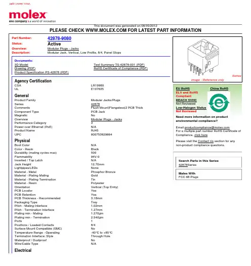
This document was generated on 08/30/2012PLEASE CHECK FOR LATEST PART INFORMATIONPart Number:42878-9080Status:ActiveOverview:Modular Plugs - JacksDescription:Modular Jack, Vertical, Low Profile, 8/4, Panel StopsDocuments:3D ModelTest Summary TS-42878-001 (PDF)Drawing (PDF)RoHS Certificate of Compliance (PDF)Product Specification PS-42878 (PDF)Agency CertificationCSA LR19980ULE107635GeneralProduct Family Modular Jacks/Plugs Series42878CommentsFlush Mount|Flangeless|2 PCB Thick Component Type PCB Jack Magnetic NoOverviewModular Plugs - Jacks Performance Category 3Power over Ethernet (PoE)N/A Product Name RJ45UPC800753829664PhysicalBoot Color N/A Color - ResinBlack Durability (mating cycles max)500Flammability94V-0Inverted / Top Latch N/AJack Height12.70mm Lightpipes/LEDs NoneMaterial - MetalPhosphor Bronze Material - Plating MatingGold Material - Plating Termination TinMaterial - Resin PolyesterOrientation Vertical (Top Entry)PCB Locator Yes PCB RetentionYes PCB Thickness - Recommended 3.18mm Packaging TypeTray Pitch - Mating Interface1.02mm Pitch - Termination Interface 1.27mm Plating min - Mating1.270µm Plating min - Termination2.540µm Ports1Positions / Loaded Contacts8/4Surface Mount Compatible (SMC)NoTemperature Range - Operating -40°C to +85°C Termination Interface: Style Through Hole Waterproof / Dustproof No Wire/Cable TypeN/AElectricalSeriesimage - Reference onlyEU RoHSChina RoHSELV and RoHS Compliant REACH SVHC Not ReviewedLow-Halogen Status Not ReviewedNeed more information on product environmental compliance?Email productcompliance@For a multiple part number RoHS Certificate of Compliance, click herePlease visit the Contact Us section for any non-product compliance questions.Search Parts in this Series 42878Series Mates With FCC 68 PlugsCurrent - Maximum per Contact 1.5AShielded NoVoltage - Maximum150V AC (RMS)Solder Process DataDuration at Max. Process Temperature (seconds)5Lead-free Process Capability Wave Capable (TH only)Max. Cycles at Max. Process Temperature1Process Temperature max. C235Material InfoReference - Drawing NumbersProduct Specification PS-42878Sales Drawing SDA-42878-****Test Summary TS-42878-001This document was generated on 08/30/2012PLEASE CHECK FOR LATEST PART INFORMATION分销商库存信息: MOLEX 0428789080。
605-00005;中文规格书,Datasheet资料

7Seg-DB (#28312 & #28313): 4-Digit, 7-Segment LED Display Module Hardware ManualGeneral DescriptionThe 7Seg-DB modules each provide 4 digits of LED display, with some alphabetic and punctuation capability. The master module, 7Seg-DB(M) (#28312), plugs directly into a Parallax motherboard. With the master module installed, up to seven additional slave modules, 7Seg-DB(S) can be added, daisy-chain-style, for a total of 32 contiguously-displayed digits.Features• Plug-compatible with Parallax motherboards.• Displays four digits (alphanumeric characters) apiece.• Includes shift registers for refresh with 25% duty cycle.• Includes a dimming input for PWM control of overall intensity.• Compatible with future daisy-chainable I/O devices.• Downloadable AVR firmware handles refresh, character display, and special effects automatically.• Compatible with both 3.3V and 5V Vdd installations.Application Ideas• Annunciators.• Visual Sensor Feedback.• Desktop weather stations.• Scrolling marquees.• Debugging output.What’s Included7Seg-DB module, LED extractor and jumper (supplied withwith amber LED master module only).What You Need to Provide• Parallax motherboard.Available Accessories• Red, green, and blue replacement displays.One master module is required for every installation. The master module can be plugged into any daughterboard socket on a Parallax motherboard. Most of the time, you’ll want to use the “B” socket, and the examples in this document use the “B” socket exclusively. Below is a photo of a master module plugged into the MoBoStamp-pe’s “B” socket:Theoretically, you could plug master modules into both sockets. However, even though they will line up with one another, one will be inverted with respect to the other. At some point, if there’s sufficient demand, there will be a firmware driver available for use with an upside-down module. But using one master with a daisy-chained slave is preferred over the two-master approach.MoBoStamp-peBefore plugging the 7Seg-DB into your MoBoStamp-pe, load the AVR firmware for this device (available for download on the 7Seg-DB product page, /detail.asp?product_id=28312. This firmware can be installed for either the “A” or “B” daughterbord sockets, socket “B” being the usual destination. The firmware is uploaded with the program, LoadAVR.exe, available on the MoBoStamp-pe product page: /detail.asp?product_id=28300. Before uploading, however, you may wish to redesign the default character set to your own specs. This can be done with the PC program, 7Seg_Font.exe, available from the 7Seg-DB product page.After successfully installing the AVR firmware, the 7Seg-DB functions can be programmed in PBASIC, as outlined in the 7Seg-DB AVR firmware manual, which is also available on the 7Seg-DB product page. MoBoPropTo use the 7Seg-DB with your MoBoProp motherboard, just plug it into either daughterboard socket, socket “B” being its usual home. To use the 7Seg-DB as an output device for the Propeller, you will need to specify the 7Seg object (available from the Propeller Object Exchange) with your programs under the “OBJ” header and call the public routines contained therein.Once the master module has been installed, up to seven additional slave modules can be plugged into it, one after the other, in a daisy chain. On the back of every purchased master module, there is a jumper installed on the two-pin, right-angle header. (See photo below.)Before plugging in the master module, remove this jumper from the master device. Then, after daisy chaining all the slave devices, install the jumper on the last device in the chain, as shown below:Once this is done, the master module with its daisy-chained slaves can be plugged into the motherboard. To support the slave units physically, Parallax will soon be offering extrusions designed for that purpose. You can also employ the screw holes (#4 or 3mm), along with standoffs for mounting behind a panel. IMPORTANT NOTE:When powering your system from the USB port, eight 7Seg-DBs running at maximum intensity will draw more current than the USB port can provide. This will cause the motherboard to reset when the USB supply voltage is drawn down too far. To avoid this, use a lower intensity setting to keep current draw to a minimum. See the AVR firmware docs for how to adjust the LED intensity.Changing LED DisplaysThe four-digit LEDs are socketed, so they can be exchanged with similar units of a different color. The sockets hold the LEDs very tightly, and they can be difficult to remove. For this reason, an extraction tool is provided for safe LED removal.IMPORTANT NOTE: Do not use any metallic implements (e.g. screwdrivers, knife blades, etc.) to extract the LED. Doing so will mar the plastic LED housing and could damage the LED and/or the 7Seg-DB printed circuit board.Using the removal tool provided, slip the thin end under the top or bottom of the LED and pry gently until it lifts slightly from the socket. Repeat on the other side. Keep switching sides and prying by little bits at a time until the LED is free.To install the replacement LED, make sure that it’s oriented correctly. Use the image printed (very faintly) on the circuit board as a guide. The decimal points indicate the correct orientation. (See photo below.)Schematic分销商库存信息: PARALLAX605-00005。
0873402096;中文规格书,Datasheet资料
This document was generated on 08/13/2012PLEASE CHECK FOR LATEST PART INFORMATIONPart Number:87340-2096Status:ActiveOverview:Milli-Grid™ Connector SystemDescription:2.00mm Pitch Milli-Grid™ Receptacle, Surface Mount (Very Low Profile), Top Entry,with Locating Pegs, with Pick-and-Place Cap, 0.38µm Gold (Au) Plating, 20 Circuits,Lead-Free, Embossed Tape on ReelDocuments:3D ModelRoHS Certificate of Compliance (PDF)Drawing (PDF)Product Literature (PDF)Agency CertificationCSA LR19980ULE29179GeneralProduct Family PCB Receptacles Series87340Application Board-to-Board, SignalOverviewMilli-Grid™ Connector System Product Literature Order No 987650-1991Product Name Milli-Grid™UPC822348473519PhysicalCircuits (Loaded)20Circuits (maximum)20Color - ResinBlack Durability (mating cycles max)25Flammability94V-0Glow-Wire Compliant No Lock to Mating Part YesMaterial - MetalPhosphor Bronze Material - Plating MatingGold Material - Plating Termination Tin Net Weight0.280/g Number of Rows 2Orientation Vertical PCB Locator Yes PCB Retention NonePackaging TypeEmbossed Tape on Reel Pitch - Mating Interface 2.00mm Plating min - Mating0.381µm Plating min - Termination 1.905µm Polarized to Mating Part No Polarized to PCB NoRobotic PlacementPick and Place Cap Surface Mount Compatible (SMC)N/ATemperature Range - Operating -55°C to +105°C Termination Interface: StyleSurface Mount ElectricalCurrent - Maximum per Contact 1A Voltage - Maximum125VMaterial InfoSeriesimage - Reference onlyEU RoHSChina RoHSELV and RoHS Compliant REACH SVHCContains SVHC: No Low-Halogen Status Not Low-HalogenNeed more information on product environmental compliance?Email productcompliance@For a multiple part number RoHS Certificate of Compliance, click herePlease visit the Contact Us section for any non-product compliance questions.Search Parts in this Series 87340SeriesMates With87759 Vertical, Surface Mount, Stackable PCB Headers, 87760 Right Angle, Through Hole, Stackable PCB Headers, 87758Vertical, Through Hole, Stackable PCB HeadersReference - Drawing NumbersSales Drawing SD-87340-**92This document was generated on 08/13/2012PLEASE CHECK FOR LATEST PART INFORMATION分销商库存信息: MOLEX 0873402096。
742792604;中文规格书,Datasheet资料
6.1 6.0 5.02012-06-262012-03-292007-02-01SStSStSKleSStSMu-Würth Elektronik eiSos GmbH & Co. KGEMC & Inductive SolutionsMax-Eyth-Str. 174638 WaldenburgGermanyTel. +49 (0) 79 42 945 - 0A Dimensions: [mm]F Typical Impedance Characteristics:Test Equipment: E4991A or equivalentF Derating Curve:H1: Classification Reflow Profile for SMT components:H2: Classification Reflow ProfilesProfile FeaturePreheat- Temperature Min (T smin ) - Temperature Max (T smax ) - Time (t s ) from (T smin to T smax )Ramp-up rate (T L to T P )Liquidous temperature (T L )Time (t L ) maintained above T L Peak package body temperature (T p )Time within 5°C of actual peak temperature (t p )Ramp-down rate (T P to T L )Time 25°C to peak temperature Pb-Free Assembly 150°C 200°C60-180 seconds 3°C/ second max.217°C60-150 seconds See Table H320-30 seconds 6°C/ second max.8 minutes max.refer to IPC/JEDEC J-STD-020DH3: Package Classification Reflow TemperaturePB-Free Assembly PB-Free Assembly PB-Free Assembly Package Thickness< 1.6 mm 1.6 - 2.5 mm ≥ 2.5 mmVolume mm³<350260°C 260°C 250°CVolume mm³350 - 2000260°C 250°C 245°CVolume mm³>2000260°C 245°C 245°Crefer to IPC/JEDEC J-STD-020DH Soldering Specifications:I Cautions and Warnings:The following conditions apply to all goods within the product series of WE-CBFof Würth Elektronik eiSos GmbH & Co. KG:General:All recommendations according to the general technical specifications of the data-sheet have to be complied with.The disposal and operation of the product within ambient conditions which probably alloy or harm the component surface has to be avoided.If the product is potted in customer applications, the potting material might shrink during and after hardening. Accordingly to this the product is exposed to the pressure of the potting material with the effect that the ferrite body and termination is possibly damaged by this pressure and so the electrical as well as the mechanical characteristics are endanger to be affected. After the potting material is cured, the ferrite body and termination of the product have to be checked if any reduced electrical or mechanical functions or destructions have occurred.The responsibility for the applicability of customer specific products and use in a particular customer design is always within the authority of the customer. All technical specifications for standard products do also apply for customer specific products.Washing varnish agent that is used during the production to clean the application might damage or change the characteristics of the plating. The washing varnish agent could have a negative effect on the long term function of the product.Direct mechanical impact to the product shall be prevented as the ferrite material of the ferrite body could flake or in the worst case it could break.Product specific:Follow all instructions mentioned in the datasheet, especially:•The solder profile has to be complied with according to the technical reflow soldering specification, otherwise no warranty will be sustai-ned.• Wave soldering is only allowed after evaluation and approval.•All products are supposed to be used before the end of the period of 12 months based on the product date-code, if not a 100% solderabi-lity can´t be warranted.•Violation of the technical product specifications such as exceeding the nominal rated current will result in the loss of warranty.1. General Customer ResponsibilitySome goods within the product range of Würth Elektronik eiSos GmbH & Co. KG contain statements regarding general suitability for certain application areas. These statements about suitability are based on our knowledge and experience of typical requirements concerning the are-as, serve as general guidance and cannot be estimated as binding statements about the suitability for a customer application. The responsibi-lity for the applicability and use in a particular customer design is always solely within the authority of the customer. Due to this fact it is up to the customer to evaluate, where appropriate to investigate and decide whether the device with the specific product characteristics described in the product specification is valid and suitable for the respective customer application or not.2. Customer Responsibility related to Specific, in particular Safety-Relevant ApplicationsIt has to be clearly pointed out that the possibility of a malfunction of electronic components or failure before the end of the usual lifetime can-not be completely eliminated in the current state of the art, even if the products are operated within the range of the specifications.In certain customer applications requiring a very high level of safety and especially in customer applications in which the malfunction or failure of an electronic component could endanger human life or health it must be ensured by most advanced technological aid of suitable design of the customer application that no injury or damage is caused to third parties in the event of malfunction or failure of an electronic component.3. Best Care and AttentionAny product-specific notes, warnings and cautions must be strictly observed.4. Customer Support for Product SpecificationsSome products within the product range may contain substances which are subject to restrictions in certain jurisdictions in order to serve spe-cific technical requirements. Necessary information is available on request. In this case the field sales engineer or the internal sales person in charge should be contacted who will be happy to support in this matter.5. Product R&DDue to constant product improvement product specifications may change from time to time. As a standard reporting procedure of the Product Change Notification (PCN) according to the JEDEC-Standard inform about minor and major changes. In case of further queries regarding the PCN, the field sales engineer or the internal sales person in charge should be contacted. The basic responsibility of the customer as per Secti-on 1 and 2 remains unaffected.6. Product Life CycleDue to technical progress and economical evaluation we also reserve the right to discontinue production and delivery of products. As a stan-dard reporting procedure of the Product Termination Notification (PTN) according to the JEDEC-Standard we will inform at an early stage about inevitable product discontinuance. According to this we cannot guarantee that all products within our product range will always be available. Therefore it needs to be verified with the field sales engineer or the internal sales person in charge about the current product availability ex-pectancy before or when the product for application design-in disposal is considered.The approach named above does not apply in the case of individual agreements deviating from the foregoing for customer-specific products.7. Property RightsAll the rights for contractual products produced by Würth Elektronik eiSos GmbH & Co. KG on the basis of ideas, development contracts as well as models or templates that are subject to copyright, patent or commercial protection supplied to the customer will remain with Würth Elektronik eiSos GmbH & Co. KG.8. General Terms and ConditionsUnless otherwise agreed in individual contracts, all orders are subject to the current version of the “General Terms and Conditions of Würth Elektronik eiSos Group”, last version available at .J Important Notes:The following conditions apply to all goods within the product range of Würth Elektronik eiSos GmbH & Co. KG:分销商库存信息: WURTH-ELECTRONICS 742792604。
0874390601;中文规格书,Datasheet资料
Agency Certification
CSA UL
General
Product Family Series Application Overview Product Name UPC Crimp Housings 87439 Signal, Wire-to-Board Pico-Spox™ Pico-SPOX™ 822350717649
Need more information on product environmental compliance? Email productcompliance@ For a multiple part number RoHS Certificate of Compliance, click here Please visit the Contact Us section for any non-product compliance questions.
/
This document was generated on 08/31/2012
PLEASE CHECK FOR LATEST PART INFORMATION
Part Number: Status: Overview: Description: Documents: 3D Model Drawing (PDF)
PLEASE CHECK FOR LATEST PART INFORMATION
分销商库存信息:
MOLEX 0874390601
87439-0601 Active
Pico-Spox™ 1.50mm Pitch Pico-SPOX™ Wire-to-Board Housing, 6 Circuits, Black Housing
744878002;中文规格书,Datasheet资料
description :A mmB mmC mmD mmE mm FmmEigenschaften / properties Wert / valueEinheit / unittol.Induktivität (je Wicklg.) /inductance (each wdg.)DC-Widerstand (je Wicklg.) /DC-resistance (each wdg)DC-Widerstand (je Wicklg.) /DC-resistance (each wdg)Nennstrom (je Wicklg.) /rated Current (each wdg.)Sättigungsstrom (je Wicklg.) /saturation current (each wdg.)Eigenres.-Frequenz /self-res.-fequency Nennspannung /rated voltage33%+20°CFerrit/ ferrite OO 09-09-01NameDatum / dateA typ.max.V80Draht / wire:max. D Prüfgeräte / test equipment :E Testbedingungen / test conditions :HP 34401 A für/for I DC und/and R DCUmgebungstemperatur / temperature:Betriebstemp. / operating temperature: -40°C - + 125°C I N1,I N20,042A Basismaterial / base material: F Werkstoffe & Zulassungen / material & approvals :G Eigenschaften / general specifications :U DCΩI sat typ.HP 4274 A für/for L und/and Q max.SRF MHz 3,60It is recommended that the temperature of the part does not exceed 125°C under worst case operating conditions................................................................................................................................Freigabe erteilt / general release:Kunde / customer.................................................Datum / date..................................................................................Unterschrift / signature Kontrolliert / approvedWürth Elektronik eiSos GmbH & Co.KGD-74638 Waldenburg · Max-Eyth-Strasse 1 - 3 · Germany · Telefon (+49) (0) 7942 - 945 - 0 · Telefax (+49) (0) 7942 - 945 - 400Geprüft / checked max.Testbedingungen / test conditions 0,052±20% B Elektrische Eigenschaften / electrical properties :Umgebungstemp. / ambient temperature: -40°C - + 85°C 53ΔT = 40 K 2 SFBW; 155°CPOWER-CHOKE WE-DDµH R DC1,2L 1,L 2 A Mechanische Abmessungen / dimensions :1 kHz / 0,25V@ 20°2,4ΩR DC1,2|ΔL/L|<10%4,80DATUM / DATE : 2009-09-014,0 ± 0,22,7 ± 0,11,0 ± 0,1@ 20°4,0 max.7,3 ± 0,4 Luftfeuchtigkeit / humidity:Würth ElektronikTyp SC Lötpad / soldering spec.:Änderung / modificationVersion 1A BCD E2314Av v v vv v v v142 L13 L2StartFinish[ mm ]0,83,12,22,21,0description :OO 09-09-01NameDatum / date.................................................................................................Geprüft / checked Kontrolliert / approvedWürth Elektronik eiSos GmbH & Co.KGD-74638 Waldenburg · Max-Eyth-Strasse 1 - 3 · Germany · Telefon (+49) (0) 7942 - 945 - 0 · Telefax (+49) (0) 7942 - 945 - 400Änderung / modificationVersion 1Freigabe erteilt / general release:Kunde / customer..................................................................................................................................................................Würth ElektronikDatum / dateUnterschrift / signaturePOWER-CHOKE WE-DDDATUM / DATE : 2009-09-01H Induktivitätskurve / Inductance curve:0,000,501,001,502,002,500,01,02,03,04,05,06,07,08,09,0L (µH )Current (A)Induktivität vs Strom (typ.) / Inductance vs Current (typ.)description :I Rollenspezifikation / tape and reel specification:A 9,00± 0,1mmB 16,0± 0,2mm + 0,1- 0,0D 4,00± 0,1mmE 2,00± 0,1mm F 9,00± 0,1mm G3,50± 0,1mma 330,0 ± 2,0mmb 21,00± 0,8mmc 13,00± 0,5mm d 100,0± 1,0mmOO 09-09-01NameDatum / date.................................................................................................Geprüft / checked Kontrolliert / approvedWürth Elektronik eiSos GmbH & Co.KGD-74638 Waldenburg · Max-Eyth-Strasse 1 - 3 · Germany · Telefon (+49) (0) 7942 - 945 - 0 · Telefax (+49) (0) 7942 - 945 - 400Änderung / modification..................................................................................................................................................................Datum / dateUnterschrift / signature Würth ElektronikFreigabe erteilt / general release:Kunde / customerDATUM / DATE : 2009-09-01mm 1,50C POWER-CHOKE WE-DDGurtspezifikation / Tape specification: Rollenspezifikation / Reel specification:Version 1Ø cadbABED øC FGThe force for tearing off cover tape is 20 to 70 grams in arrow direction150°feeding directionThis electronic component has been designed and developed for usage in general electronic equipment. Before incorporating this component into any equipment where higher safety and reliability is especially required or if there is the possibility of direct damage or injury to human body, for example in the range of aerospace, aviation, nuclear control, submarine, transportation, (automotive control, train control, ship control), transportation signal, disaster prevention, medical, public information network etc, Würth Elektronik eiSos GmbH must be informed before the design-in stage. In addition, sufficient reliability evaluation checks for safety must be performed on every electronic component which is used in electrical circuits that require high safety and reliability functions or performance.分销商库存信息: WURTH-ELECTRONICS 744878002。