阿里斯顿热水器维修
阿里斯顿JSQ26-Hi7、Ei7+说明书

4.3 向浴缸内注水4.3.1使用前准备¥ 关闭浴缸的放水栓;¥ 如果有浴缸盖请盖上。
(注水时请打开)4.3.2 通过面板操作器注水时请按照以下的方法进行A. 初次使用时,按下面板操作器的电源开关,面板显示器闪烁显示标准模式的水温"42℃",3秒钟后显示实际出水温度。
标准模式下的水温(例42℃)标准模式下的水温(例42℃)优先显示亮¥ 热水器的设定温度范围为35℃-70℃,在温度范围35℃-48℃区间内,按下温度设定按键以1℃为单位上升或下降,而 且设定完温度时,会闪烁显示3秒设定温度,随后显示实际水温;在温度范围50℃-70℃区间,按下温度设定按键是以 5℃为单位上升或下降,且设定温度完成后会闪烁10秒显示设定温度,随后显示实际水温。
¥ 为了使机器在进水温度较低的情况下,也能达到更好的恒温使用性能,在部分额定热负荷较小的机型上特设水量调节 旋钮。
当出现出水温度低于设定温度时,请将水量调节旋钮适当关小, 使得到最佳的恒温调节范围.”¥ 当超出机器使用范围而无法达到设定温度,不属于产品质量问题,可通过调节进水量达到设定温度.4.2 水温调节¥ (热水器同时连接面板操作器和浴室有线遥控器时)正在使用热水时¥ 无法从35~48℃的温度设定改变为高温(50℃,55℃,60℃,65℃,70℃)。
¥ 设定为高温(50℃,55℃,60℃,65℃,70℃)时,无法升高温度。
Hi7机型:Ei7+/Ei6+机型:¥ Hi7系列通过按auto 按键,使LCD 上的"浴缸模式"闪烁,同时显示屏会闪烁显示水量设定值,此时可通过上下键设定水 量。
¥ 对Ei7+和Ei6+系列按下水量设定开关,LCD 显示屏会闪烁显示水量设定值时,按触上下按键进行水量设定。
¥ 设定水量范围为10~990升(每10升为1单位),用户可根据自己需求任意设定。
Ariston电热水器维修手册说明书

1.AR2700, AR2788, AR2788S, FA1000, FA1234Problem and SolutionUnit Will Not Power UpTurn the power switch on. The unit LCD will display revision program and filter life within 3 to 5 seconds after turning on unit.If this process does not happen then see the trouble shooting tips below.1.Check power cord is firmly plugged into unit all the way.2.Check Circuit breaker on unit. Check that it is not tripped.3.Check power source to unit. Check with voltage meter. (The fan will run as soon asyou plug it in on the following unit listed by serial number.)a.AR2700 Serial Numbers Beyond to 03/13 AR00764b.AR2788 Nonec.AR2788S Serial Numbers Beyond to 10/12 AR001844d.FA1000 Alle.FA1234 All4.Check for LED light on main PCB is powered up. Open top panel to see lights onMain PCB.5.Check power to the power supply PCB (120 volts AC in) and power from the (PCB12 volts DC out).6.Check Contrast on PCB for adjustment.7. Unit passes the above checklist. The LCD or Main PCB maybe bad.a.If the LCD is bad and main PCB is good. The unit will go through PT setup,but no display on screen.b.If the LCD is good even there is no display showing and Main PCB is bad. Theunit will not run through PT setup.Unit Stuck In PT Calibration ModeTurn the power switch on. The unit LCD will display revision program and filter life within 3 to 5 seconds after turning on unit. Then the Please wait PT CAL with display a second or two after filter life. During the PT CAL the recovery compressor will run first until PT is satisfied. After compressor turns then 40 seconds later the vacuum pump will run for 4 seconds and turn off. The unit will then look to see if air purge is needed. If noair purge is needed then the unit displays Main Menu. This process from turning unit onto main menu display is 90 seconds. Note: If the unit needs to purge then process willtake longer than the 90 seconds. Additional 5 minutes is possible depending on pressurein recovery tank being purged.If the above process does not happen then see trouble shooting tips below.1.Check oil injection bottle assembly.a.Oil Injection bottle is tight to the back of the unit.b.Check that the oil injection valve is closed. (Earlier unit had flip level.)2. Check that recovery compressor turns on and then off. Compressor will turn off once vacuum is satisfied on Pressure Transducer3. Check that vacuum pump on/off switch is in the on position. (I)4. Check that the vacuum pump power cord is plugged in firmly both ends.5. Check that vacuum pump is good.a.Plug vacuum pump directly into power source using main power cord.6.Vacuum Pump runs constantly. (Should run for 4 seconds during PT Cal)a.Check yellow batch cord on main PCB and Low side block.b.Check oil level on vacuum pump. (Vacuum pump over filled won’t pullvacuum.)7. Check tank pressure and manually purge tank if needed.a.Connect red service hose to filter block red cap on top of tank. Open red tankvalve, ball valve on hose from liquid tank valve to filter, and red service8. AR2788 units only manually re calibrate Pressure Transducer.Unit Stuck In Air Purge1.Air Purge has a five minute time limit.2.To reset unit press the bottom key button after 5 minutes.3.Check tank pressure and manually purge tank if needed.a.Connect red service hose to filter block red cap on top of tank. Open redtank valve, ball valve on hose from liquid tank valve to filter, and redservice coupler. Tank presser will display on red high side gauge.4. AR2788 units only manually re calibrate Pressure Transducer.Oil Drain Bottle Cap Blew Off (Prior to Serial No. Rev. 5.1.81.Check tank valve and tank hose are open.2.Check tank pressure and manually purge tank if needed.a.Connect red service hose to filter block red cap on top of tank. Open red tankvalve, ball valve on hose from liquid tank valve to filter, and red servicecoupler. Tank presser will display on red high side gauge.Unit Will Not Inject Oil1. Vacuum pump ran for 15 minutes on closed system, and 45 open system.2.Check service couplers are open.3.Unit gauges are showing a vacuum before open oil injection valve.4.Check that oil injection is tight on back of unit.5.Unit oil injection bottle has oil in it.6.Check valve at the end of the pick up tube in oil injection bottle is stuck.1.Check for pressure on gauges.2.Checks the service couplers are open.3.Check tank valve are open.4.Check that the compressor is running.5.Check tank pressure and manually purge tank if needed.a.Connect red service hose to filter block red cap on top of tank. Open redtank valve, ball valve on hose from liquid tank valve to filter, and redservice coupler. Tank presser will display on red high side gauge.6. Manually purge Compressor on suction and discharge port.1.Check for pressure on Red gauge.2.Checks the Red service coupler is open.3.Check tank valve are open.4.Check that the virgin tank bottle valve is open.5.Check that the compressor is running.6.Check tank pressure and manually purge tank if needed.a.Connect red service hose to filter block red cap on top of tank. Open redtank valve, ball valve on hose from liquid tank valve to filter, and redservice coupler. Tank presser will display on red high side gauge.7. Manually purge Compressor on suction and discharge port.Unit Will Not Pull Into Vacuum During Recovery1.Check the service couplers are tight to service hoses.2.Check that the compressor is running.3.Check that the oil injection bottle valve is closed and tight to unit.4.Check that gauges are calibrated.a. Remove couplers from service hoses. Gauges should read 0 PSI. If adjustmentis needed, then remove plastic plug from plastic lenses and adjust to 0 psi.5.Check that the o rings in service couplers are good. Remove couplers from carservice ports and recover hoses. If gauge pull down into vacuum o rings needreplaced.6.Check tank pressure and manually purge tank if needed.a. Connect red service hose to filter block red cap on top of tank. Open red tankvalve, ball valve on hose from liquid tank valve to filter, and red service coupler.Tank presser will display on red high side gauge.Unit Vacuum Pump Will Not Pull Deep Vacuum1.Check the service couplers are tight to service hoses.2.Check that vacuum pump is running.3.Check that oil level in sight glass is not over filled.4.Check that gauges are calibrated.a. Remove couplers from service hoses. Gauges should read 0 PSI. Ifadjustment is needed, then remove plastic plug from plastic lenses and adjust to 0 psi.5.Check that oil injection bottle valve is closed and tight to unit.6.Check o rings in service couplers are good. Remove couplers from car serviceports and recover hoses. If gauge pull down into vacuum o rings need replaced.Unit Will Not Charge1.Display stated unit charging, but weight showed the unit did not put anyrefrigerant in (Hose holds 2 oz). Then the check connection message came up on display after two minutes.2.Check that the Red gauge is reading pressure, if so then the Charge solenoid isworking. If the Red gauge is still in vacuum need to continue to next step.3. Check the valves on the recovery tank and tank hoses ball valves are open.4.Check that the service couplers are open.5.Check that there is refrigerant available for charging. (4 to 5 lbs in tank aftercharge selected).6.Check service couplers for flow restriction.7.Check that the solenoid Valve is clicking after starting charge mode. The lightnext to the LS1 orange connector on low side block PCB should be energizedwith red light.a. If red light is on, but solenoid not clicking. Remove connector if it is old styleconnector orange in color from low side block PCB and push both black wiresfurther down in connector.Unit Will Not Complete Charge1.Display stated unit charging with pressure on gauges, but did not complete the fullcharge. (Normally at least half the charge was dispensed). Then the checkconnection message came up on display after two minutes.2.Check that there is refrigerant available for charging. (4 to 5 lbs in tank aftercharge selected).3.Vacuum pump ran for 15 minutes on closed system, and 45 minutes on openedsystem for deep vacuum.e low side adaptor to complete charge AR2788, AR2788S. FA unit turn hi sideadaptor off, and start car.E5 Ball Valve Error Message1.E5 is motorized ball valve error.∙LV in the message indicates low side valve.∙HV in the message indicates hi side valve∙Number indicated which valve is having trouble.2.Check connector on PCB for motorized ball valve location.3.The old blue connector only. You can remove connector from PCB and pushwire further into connector for better connection.High Pressure Cut out 450psi1.Check tank and hose valves are open.2.Check tank pressure.3.Check orange high pressure switch wire for connection.LCD Display Is Dim or Read out1.Adjust contrast on main PCB2.Unit cannot be in the direct sun light.Changing Filter1. Remove filter from tank bracket and turn filter 90 degrees with black blockwith red and blue caps pointed downwards. It will cut 30 minutes off recovering filter.2. Close red tank valve off to prevent additional refrigerant into filter.3. Connect red and blue service hoses to black block on filter.Air Flow Switch E-15 Error1.Check wire connection on main PCB two purple wires. (FA1234 unit only)2.Check that the air flow switch assembly has two clear PVC tubes attachedproperly. (FA1234 unit only)3.Jump out two pins on main PCB where flow switch wire connect to confirm wiresor flow switch is bad.。
阿里斯顿热水器故障代码
阿里斯顿热水器故障代码热水器常见问题及处理方法故障一、在正常加热下突然跳闸/原因1:插头与插座接触不实,插头起热。
漏电保护开始弹跳,断电。
2:插座上的线太细,热水器功率过大。
处理:更换插座或者换线。
故障二、未加热时不产生漏电,加满水后产生漏电原因:1:水压过大,安全阀漏水。
2:内胆漏水。
处理:更换安全阀,更换内胆。
故障三、加热指示灯亮,但不能加热原因1:发热管接插端接触不良或断线;处理:检查排除;原因2:发热管烧坏;处理:更换发热管。
故障四、加热指示灯不亮,不能加热原因1:温控器接插端接触不良或断线;处理:检查排除;原因2:温控器烧断;处理:更换温控器。
故障五、热水器指示灯一直不灭原因:温控器感温面与电热管法兰面接触点少;处理:重新安装温控器,使感温平面接触。
故障六、无保温功能,一直加热下去,直到跳闸原因:温控器动作温度过高或已烧融短路;处理:更换温控器。
故障七、加热时间过长原因1:热水器未使用最高功率档加热(有功率转换功能的电热水器而言);处理:把功率转换开关旋到最大功率档;原因2:电热管坏;处理:更换电热管。
故障八、一直处于保温状态,不能重新加热原因:温控器不能复位一直处于开路;处理:更换温控器。
故障九、热水器加热过程中,安全阀小孔有水珠滴出原因:由于电热水器属于贮水式封闭型电热水器,在加热或保温过程中,热水器内胆的水压大于6Mpa,使单向安全阀溢压而滴出水珠;处理:关闭进水阀,将混水阀旋钮调到高温处即可避免单向安全阀的漏水现象,使水从花洒中滴出;如果未安装混水阀,可把出热水球阀打开一点,在此处泄压流水,也可避免单向安全阀的漏水现象。
故障十、加热指示灯不亮,但能正常加热原因:指示灯接插触不良或断线。
指示灯坏。
处理方法:检查排除、更换指灯。
故障十一、无保温功能,一直加热下去,直到温跳闸原因:温控器动作温度过高或已烧融短路;处理方法:更换温控器。
故障十二、一直处于保温状态,不能重新加热原因:温控器不能复位一直处于开路;处理方法:换温控器。
阿里斯顿JSQ-20热水器说明书

目录功能与特点 (1)各部分零件名称 (2)使用前准备 (5)使用方法 (6)使用注意事项 (10)防冻注意事项 (12)安装 (13)试运行 (19)日常检查及保养 (19)故障、异常的判断及处理方法 (20)规格表 (21)配线图 (22)一.功能与特点一. 功能与特点采用静电喷涂处理,可搭配各款现代厨房设计,结构紧凑,机身小巧,大大节省了安装空间。
操作简单双低压启动缓点火设计操作面板显示水温调节方便可拆式过滤装置瞬间停电或降压的安全保护设计1外型美观12345678多重安全保护装置,使用更放心10● 自动熄火保护装置, 使用过程中发生意外熄火时,本机会自动关闭气源,防止燃气外泄,安全可靠。
● 超时使用安全装置,连续使用30分钟后,热水器自动停机,若要继续使用,只需关上热水阀,数秒后再开启即 可重新点火。
● 强制鼓风燃烧方式设计,采用高效能风机将烟气全部排放室外,确保使用安全。
●另配有过热保护装置,水过压泄压装置,风机停转安全保护装置,防止空烧安全保护装置,排烟管堵塞保护装 置,防冻保护装置(仅限防冻机型)等,确保热水器在正常状态下工作。
●Pa1/Pa2机型使用auto功能模式时有48°安全锁保护。
●Pb1机型提供使用48°安全锁保护的选项,使用此选项可确保热水器在出水温度不高于48°的火力分段下燃烧, 确保您的安全使用。
当供电网络电压瞬间跌落或停电时,仍能保持热水器正常工作或安全停机。
自动变升功能(Pa1/Pa2)9特设有自动变升功能,在自动变升模式下使用时,系统会根据用户的实际需求与季节不同,自动变升调节火力段进行燃烧,以最优化的状态工作,节能省气。
省电设计11本机处于待机并显示屏点亮的状态下,如2分钟内未做任何操作,则显示器背光源会关闭,如需查看只需按触电源开关按键则背光源点亮。
P1/Pa1/Pb1面板操作器可以自由调控升位大小,燃烧指示灯显示工作状态;Pa2 LED数码显示屏显示出水温度、升位大小及工作状态,一目了然 。
ariston热水器控制面板说明书
ariston热水器控制面板说明书
Ariston热水器控制面板是一个简单易用的控制面板,它提供了多种
功能和设置选项,以满足用户的不同需求。
以下是该控制面板的详细说明:1. 开/关按钮:该按钮用于打开或关闭热水器。
2. 模式选择按钮:该按
钮用于选择不同的热水器模式,包括手动模式、自动模式和定时模式。
3. 温度调节按钮:该按钮用于调节热水器的水温,可以根据需要将水温调节
到合适的温度。
4. 定时器设置按钮:该按钮用于设置热水器的定时器,
可以根据需要设置热水器的开关时间。
5. 显示屏:该显示屏用于显示热
水器的状态和设置信息,包括水温、模式、定时器等。
6. 故障指示灯:
该指示灯用于指示热水器是否出现故障,如果出现故障,指示灯将亮起。
7. 加热指示灯:该指示灯用于指示热水器是否正在加热水,如果正在加
热水,指示灯将亮起。
总之,Ariston热水器控制面板是一个功能齐全、
易于操作的控制面板,可以满足用户的不同需求,让用户轻松地控制热水
器的使用。
阿里斯顿 电热水器 说明书

特殊人群(儿童、老、弱、病、残)等淋浴时需 在他人正确操作指导下进行。
4.1.3
TS40M2.5 TS50M2.5 TS60M2.5 TS80M2.5 TS100M2.5
L型安装附件尾部有两道环形标识。 外露长度如上图所示,墙壁在两环 之间即可。
306 438 254 337 489
注意:热水器应安装在室内。 在冬天长期不用的时候,建议把热水器内的 水排空,以免热水器内结冰造成危害。用户 如需排空热水器内的水,请按7.1执行或与当 地客户服务部门联系。
安装时应确保安全阀的泄水口或与之连接的排泄管 C连续向下,将排泄水导入排水系统(如水桶、地 沟等),排泄管要安装在无霜的环境中。
开机,选择加热功率
6.1.1 将插头插入插座以接通电源,按照5.2.1试验,如试验正常可以进入下一步骤。 6.1.2 热水器的加热功率是由翘板开关上的两个按键控制的,“l”端按下时为接通,“O”端按下 时为断开,当某个按键选择接通时其上面的指示灯常亮。两个按键分别对应 1000W、1500W 的加热 功率(开关下方有标识),两个按键同时接通表明热水器处于 2500W 加热功率的工作状态。用户可 根据具体状况选择合适的加热功率,当两个按键同时断开时热水器停止工作。
60 ~ 220V 50Hz 2500 ≤ 0.8 24 465 717 252.5
80 ~ 220V 50Hz 2500 ≤ 0.8 26 465 800 252.5 100 ~ 220V 50Hz 2500 ≤ 0.8 30 465 952 252.5
棕色
K
MT
M
棕色 L
棕色
棕色
P
黄绿色
E
N 蓝色
阿里斯顿80升电热水器说明书
阿里斯顿80升电热水器说明书一、推出PROTECH倍恒科技,潜艇级防腐技术完美实现终生免保养;大家都知道水中含有多种杂质,长期使用会腐蚀热水器内胆,造成漏水,影响电热水器使用寿命。
阿里斯顿创新将潜水艇的尖端防腐技术应用到电热水器内胆保护领域,这种技术可以抵御海水的腐蚀,所以普通日常用水的那点腐蚀性自然不在话下。
终身免保养,省钱又省心,性价比高。
二、零等待速热科技,热水一触即发,轻松实现即开即洗,让沐浴随心所浴普通的电热水器在使用的时候需要提前进行加热,花费时间。
阿里斯顿创新零等待速热科技,颠覆传统级平板电热水器,真正的即开即洗,无需等待。
机器在使用过程中都会或多或少的因为操作不当或者外部因素出现故障,我们以晶蓝系列机型为例,总结到了阿里斯顿热水器说明使用以及相应的解决方法。
1.风机、风压开关、烟管道故障。
处理方法:重新启动,并且检查热水器管道有无堵塞。
2.点火失败。
处理方法:需要进行手动复位,然后检查燃气开关,保证热水器的燃气供气正常。
3.采暖温度传感器故障、传感器过热。
处理方法:需要进行复位操作,或者是断电重启,如果两个方法都不行,需要报修。
4.淋浴温度传感器故障、传感器过热。
处理方法:需要进行复位操作,或者是断电重启,如果两个方法都不行,需要报修。
5.EEROM,芯片故障。
处理方法:这时候进行必要的手动复位,然后没有效果就要进行报修。
6.热水器系统缺水。
处理方法:进行复位操作或者是断电重启。
然后检查压力表水压是否过低,进行重新的注水。
7.假火焰,没有实际的温度上升。
处理方法:复位或者是断电重启。
8外界因素熄火,热水器不正常工作。
处理方法:检查家中是否停气,然后查看烟道是否是处于迎风状态,如果都不是需要进行报修。
9.热水器机械温控过热保护。
处理方法:询问用户暖气管道是否是关闭的,如果一切正常,需要进行报修。
自己动手修理家用电热水器漏水及更换镁棒
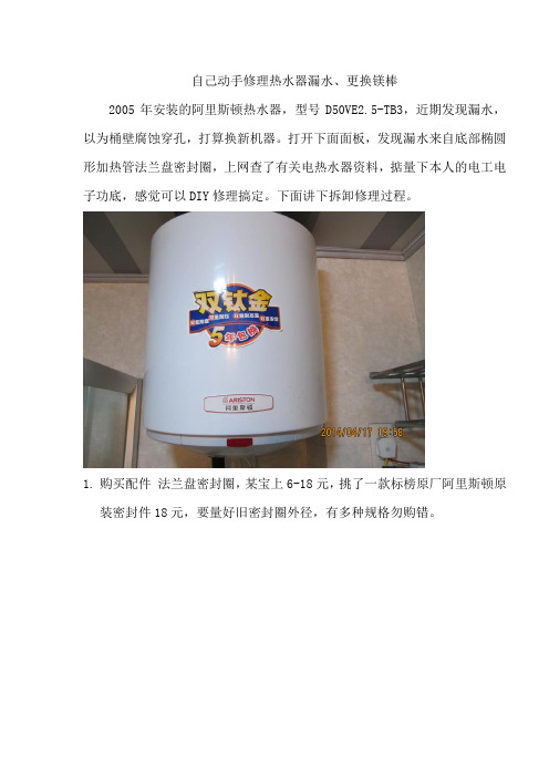
自己动手修理热水器漏水、更换镁棒2005年安装的阿里斯顿热水器,型号D50VE2.5-TB3,近期发现漏水,以为桶壁腐蚀穿孔,打算换新机器。
打开下面面板,发现漏水来自底部椭圆形加热管法兰盘密封圈,上网查了有关电热水器资料,掂量下本人的电工电子功底,感觉可以DIY修理搞定。
下面讲下拆卸修理过程。
1.购买配件法兰盘密封圈,某宝上6-18元,挑了一款标榜原厂阿里斯顿原装密封件18元,要量好旧密封圈外径,有多种规格勿购错。
2.镁棒,8-11元,长短与原件相仿,量好旧镁棒螺杆直径,注意用卡尺,用直尺量有误差会买小。
3.拆解前拍照,注意标记每根接线位置。
此款热水器法兰盘有两组加热管,一根空芯不锈钢管,内置温控器探头,与冰箱内用的温控器相似,还有一根探头可能是温度显示热电偶。
法兰盘上还有一根防腐蚀的镁棒,镁棒所在的法兰盘通过密封圈与钢桶绝缘,中间的水体为电解液,组成原电池,牺牲镁棒,保护桶壁。
令人费解的是,镁棒与法兰盘上的加热管是不绝缘的,相当于短路,对加热管的不锈钢外壁保护作用有限。
4.控制电路板上有一磁圈,内穿两根电线,猜测是相线零线,漏电发生时不平衡触发漏电保护电路动作。
5.法兰盘取出时要用巧劲,椭圆形的外形,转动角度方可取出。
6.9年未清洗的机器内部水垢污泥有1-2斤,加热管布满水垢,不锈钢管腐蚀不明显,镁棒已基本融化,热水器内壁锈蚀还好,只有几个点状锈斑,位置深,不知道是否锈蚀深部。
7.拆洗后安装镁棒,加装密封圈,紧固螺丝,插入温控器探头、热电偶。
复位各种接线,灌水,放出空气。
8.清洗后的加热管9.通电前安全检查:确保有一根花线是接地线拧在钢桶壁上,万用表电阻档检查热水器插头接地端与钢桶相通,相线零线与钢桶壁绝缘。
按下外接的触电保护器试验按钮看是否跳闸。
10.确保加水满桶后通电,一切OK11.家里的喵星人是监工。
- 1、下载文档前请自行甄别文档内容的完整性,平台不提供额外的编辑、内容补充、找答案等附加服务。
- 2、"仅部分预览"的文档,不可在线预览部分如存在完整性等问题,可反馈申请退款(可完整预览的文档不适用该条件!)。
- 3、如文档侵犯您的权益,请联系客服反馈,我们会尽快为您处理(人工客服工作时间:9:00-18:30)。
家里的阿里斯顿热水器使用时间久了之后,就可能出现一些故障问题,我们就需要及时进行维修,下面就一起来看看的故障以及维修方法吧。
1.故障:电源问题
解决:检查一下电池是否过于陈旧,电源指示灯是否正常亮起来的。
如果排除了电源供电的问题,那就更换新的电池试试。
2.故障:电磁阀问题
解决:在点火的时候听下点火声,如果没有电磁阀的声音,那很有可能是电磁阀老化了。
在确认电磁阀好坏之前要确认点火器控制电路是否正常,若有故障,不能控制电磁阀吸合。
3.故障:点火瓷针故障
解决:点火瓷针积碳太多也会造成点火不畅。
检查点火瓷针是否是有偏移位置或者是老化的现象,可以将点火针正确的安放。
可以先擦拭干净点火针试试。
4.故障:水气联动装置故障
解决:检查水气联动阀内鼓膜是否老化或者损坏,如果是就不能推动微动开关,这时候只有更换水气联动阀或者是进行维修。
燃气热水器的外部清洁,经常用湿毛巾擦拭即可,注意不能使用酸性碱性等
一系列清洗剂去擦拭热水器。
需要经常检查供气管道(橡胶软管)是否完好,有无老化、裂纹、渗漏等现象,发现有不良现象时要及时处理,经常检查。
燃气热水器出水不畅会造成不启动不工作的现象发生,因此,用户需要经常清理过滤网上的杂质和水垢,保持进出水畅通。
当燃气热水器出现漏气、漏水、停水后火焰不灭、燃烧工况不良等现象时,应停止使用,及时通知燃气管理部门或生产厂家修理,严禁私自拆卸修理。
快益修以家电、家居生活为主营业务方向,提供小家电、热水器、空调、燃气灶、油烟机、冰箱、洗衣机、电视、开锁换锁、管道疏通、化粪池清理、家具维修、房屋维修、水电维修、家电拆装等保养维修服务。