IPC-A-610国际标准中英文对照(doc17)
IPC-A-610F中文版电子组件的检验标准可接受性

IPC-A-610F CN 电子组件的可接受性2014前⾔.................................... 1-1 1.1 范围................................... 1-2 1.2 ⽬的................................... 1-3 1.3 员⼯熟练程度.......................... 1-3 1.4 分级................................... 1-3 1.5 对要求的说明.......................... 1-31.5.1 验收条件............................ 1-4 1.5.1.1 目标条件............................ 1-4 1.5.1.2 可接受条件.......................... 1-4 1.5.1.3 缺陷条件............................ 1-4 1.5.1.3.1 处置................................ 1-4 1.5.1.4 制程警示条件........................ 1-4 1.5.1.4.1 制程控制方法........................ 1-4 1.5.1.5 组合情况............................ 1-4 1.5.1.6 未涉及情形.......................... 1-5 1.5.1.7 特殊设计............................ 1-51.6 术语和定义............................ 1-51.6.1 板面方向............................ 1-5 1.6.1.1 *主面................................ 1-5 1.6.1.2 *辅面................................ 1-5 1.6.1.3 *焊接起始面.......................... 1-5 1.6.1.4 *焊接终止面.......................... 1-5 1.6.2 *冷焊接连接.......................... 1-5 1.6.3 电气间隙............................ 1-5 1.6.4 FOD(外来物) ........................ 1-5 1.6.5 高电压.............................. 1-5 1.6.6 通孔再流焊.......................... 1-6 1.6.7 弯月形涂层(元器件) .................. 1-6 1.6.8 *非功能盘............................ 1-6 1.6.9 针插焊膏............................ 1-6 1.6.10 焊料球.............................. 1-6 1.6.11 线径................................ 1-6 1.6.12 导线重叠............................ 1-6 1.6.13 导线过缠绕.......................... 1-61.7 图例与插图............................ 1-61.8 检查⽅法.............................. 1-6 1.9 尺⼨鉴定.............................. 1-6 1.10 放⼤辅助装置......................... 1-61.11 照明.................................. 1-72 适⽤⽂件................................ 2-1 2.1 IPC标准............................... 2-1 2.2 联合⼯业标准.......................... 2-1 2.3 EOS/ESD协会标准..................... 2-2 2.4 电⼦⼯业联合会标准.................... 2-2 2.5 国际电⼯委员会标准.................... 2-2 2.6 美国材料与测试协会.................... 2-22.7 技术出版物............................ 2-23 电⼦组件的操作.......................... 3-1 3.1 EOS/ESD的预防........................ 3-23.1.1 电气过载(EOS) ....................... 3-3 3.1.2 静电释放(ESD) ....................... 3-4 3.1.3 警告标识............................ 3-5 3.1.4 防护材料............................ 3-6 3.2 EOS/ESD安全⼯作台/EPA ............... 3-73.3 操作注意事项.......................... 3-93.3.1 指南................................ 3-9 3.3.2 物理损伤........................... 3-10 3.3.3 污染............................... 3-10 3.3.4 电子组件........................... 3-11 3.3.5 焊接后............................. 3-11 3.3.6 手套与指套......................... 3-12⽬录IPC-A-610F 2014年7月ix4 机械零部件.............................. 4-1 4.1 机械零部件的安装...................... 4-24.1.1 电气间隙............................ 4-2 4.1.2 妨碍................................ 4-3 4.1.3 大功率元器件安装.................... 4-4 4.1.4 散热装置............................ 4-6 4.1.4.1 绝缘垫和导热复合材料................ 4-6 4.1.4.2 接触................................ 4-8 4.1.5 螺纹紧固件和其它螺纹部件的安装...... 4-9 4.1.5.1 扭矩............................... 4-11 4.1.5.2 导线............................... 4-134.2 螺栓安装............................. 4-15 4.3 连接器插针........................... 4-164.3.1 板边连接器引针..................... 4-16 4.3.2 压接插针........................... 4-17 4.3.2.1 焊接............................... 4-204.4 线束的固定........................... 4-234.4.1 概述............................... 4-23 4.4.2 连轧............................... 4-26 4.4.2.1 损伤............................... 4-274.5 布线–导线和线束..................... 4-284.5.1 导线交叉........................... 4-28 4.5.2 弯曲半径........................... 4-29 4.5.3 同轴线缆........................... 4-30 4.5.4 空置线头........................... 4-31 4.5.5 接头和焊环上的扎点................. 4-325 焊接.................................... 5-1 5.1 焊接可接受性要求...................... 5-3 5.2 焊接异常.............................. 5-45.2.1 暴露金属基材........................ 5-4 5.2.2 针孔/吹孔........................... 5-6 5.2.3 焊膏再流............................ 5-7 5.2.4 不润湿.............................. 5-85.2.5 冷焊/松香焊接连接................... 5-95.2.6 退润湿.............................. 5-95.2.7 焊料过量........................... 5-105.2.7.1 焊料球_________............................. 5-115.2.7.2 桥连............................... 5-125.2.7.3 锡网/泼锡.......................... 5-135.2.8 焊料受扰........................... 5-145.2.9 焊料开裂. .......................... 5-155.2.10 拉尖............................... 5-165.2.11 无铅填充起翘....................... 5-175.2.12 无铅热撕裂/孔收缩. ................. 5-185.2.13 焊点表面的探针印记和其它类似表面状况......................... 5-196 端⼦连接................................ 6-16.1 铆装件................................ 6-26.1.1 接线柱.............................. 6-26.1.1.1 接线柱基座-焊盘间隙................. 6-26.1.1.2 塔形................................ 6-36.1.1.3 双叉形.............................. 6-46.1.2 卷式翻边............................ 6-56.1.3 喇叭口形翻边........................ 6-66.1.4 花瓣形翻边.......................... 6-76.1.5 焊接................................ 6-86.2 绝缘⽪............................... 6-106.2.1 损伤............................... 6-106.2.1.1 焊前............................... 6-106.2.1.2 焊后............................... 6-126.2.2 间隙............................... 6-136.2.3 挠性套管........................... 6-156.2.3.1 放置............................... 6-156.2.3.2 损伤............................... 6-176.3 导体.................................. 6-186.3.1 形变............................... 6-186.3.2 损伤............................... 6-196.3.2.1 多股导线........................... 6-196.3.2.2 实芯线............................. 6-206.3.3 股线发散(鸟笼形)–焊前............ 6-206.3.4 股线发散(鸟笼形)–焊后............ 6-216.3.5 上锡............................... 6-226.5 应⼒释放............................. 6-256.5.1 线束............................... 6-256.5.2 引线/导线弯曲...................... 6-26 6.6 引线/导线放置–通⽤要求.............. 6-28 6.7 焊接–通⽤要求....................... 6-30 ⽬录(续)x 2014年7月IPC-A-610F6.8 塔形和直针形......................... 6-316.8.1 引线/导线放置...................... 6-316.8.2 塔形和直针形–焊接................ 6-336.9 双叉形............................... 6-346.9.1 引线/导线放置–侧面进线连接........ 6-346.9.2 引线/导线放置–导线的加固.......... 6-376.9.3 引线/导线放置–底部和顶部进线连接.. 6-386.9.4 焊接............................... 6-396.10 槽形................................. 6-426.10.1 引线/导线放置...................... 6-42 6.10.2 焊接............................... 6-436.11 穿孔形............................... 6-446.11.1 引线/导线放置...................... 6-44 6.11.2 焊接............................... 6-466.12 钩形................................. 6-476.12.1 引线/导线放置...................... 6-47 6.12.2 焊接............................... 6-496.13 锡杯................................. 6-506.13.1 引线/导线放置...................... 6-50 6.13.2 焊接............................... 6-526.14 AWG30及更细的导线–引线/导线放置.. 6-54 6.15 串联连接............................ 6-557 通孔技术................................ 7-1 7.1 元器件的安放.......................... 7-27.1.1 方向................................ 7-2 7.1.1.1 方向–水平.......................... 7-3 7.1.1.2 方向–垂直.......................... 7-5 7.1.2 引线成形............................ 7-6 7.1.2.1 弯曲半径............................ 7-6 7.1.2.2 密封/熔接处与弯曲起始处之间的距离... 7-7 7.1.2.3 应力释放............................ 7-8 7.1.2.4 损伤............................... 7-10 7.1.3 引线跨越导体....................... 7-11 7.1.4 通孔阻塞........................... 7-12 7.1.5 DIP/SIP器件和插座.................. 7-13 7.1.6 径向引线–垂直..................... 7-15 7.1.6.1 限位装置........................... 7-16 7.1.7 径向引线–水平..................... 7-18 7.1.8 连接器............................. 7-19 7.1.8.1 直角............................... 7-21 7.1.8.2 带侧墙的插针头和直立插座连接器..... 7-22 7.1.9 导体外壳........................... 7-237.2 元器件的固定......................... 7-237.2.1 固定夹............................. 7-23 7.2.2 粘合剂粘接......................... 7-25 7.2.2.1 粘合剂粘接–非架高元器件........... 7-26 7.2.2.2 粘合剂粘接–架高元器件............. 7-29 7.2.3 其它器件........................... 7-30 7.3 ⽀撑孔............................... 7-317.3.1 轴向引线–水平..................... 7-31 7.3.2 轴向引线–垂直..................... 7-33 7.3.3 导线/引线伸出...................... 7-35 7.3.4 导线/引线弯折...................... 7-36 7.3.5 焊接............................... 7-38 7.3.5.1 垂直填充(A) ....................... 7-41 7.3.5.2 焊接终止面–引线到孔壁(B) ......... 7-43 7.3.5.3 焊接终止面–焊盘区覆盖(C) ......... 7-45 7.3.5.4 焊接起始面–引线到孔壁(D) ......... 7-46 7.3.5.5 焊接起始面–焊盘区覆盖(E) ......... 7-47 7.3.5.6 焊料状况–引线弯曲处的焊料......... 7-487.3.5.7 焊料状况–接触通孔元器件本体....... 7-49 7.3.5.8 焊料状况–焊料中的弯月面绝缘层..... 7-50 7.3.5.9 焊接后的引线剪切................... 7-52 7.3.5.10 焊料内的漆包线绝缘层............... 7-53 7.3.5.11 无引线的层间连接–导通孔........... 7-54 7.3.5.12 子母板............................. 7-55 7.4 ⾮⽀撑孔............................. 7-587.4.1 轴向引线–水平..................... 7-58 7.4.2 轴向引线–垂直..................... 7-59 7.4.3 引线/导线伸出...................... 7-60 7.4.4 引线/导线弯折...................... 7-61 7.4.5 焊接............................... 7-63 7.4.6 焊接后的引线剪切................... 7-657.5 跳线.................................. 7-667.5.1 导线的选择......................... 7-66 7.5.2 布线............................... 7-67 7.5.3 导线的固定......................... 7-69 7.5.4 支撑孔............................. 7-71 7.5.4.1 支撑孔–引线在孔内................. 7-71 7.5.5 缠绕连接........................... 7-72 7.5.6 搭焊连接........................... 7-73⽬录(续)IPC-A-610F 2014年7月xi8 表⾯贴装组件............................ 8-1 8.1 粘合剂固定............................ 8-38.1.1 元器件粘接........................ 8-38.1.2 机械强度.......................... 8-4 8.2 SMT引线.............................. 8-68.2.1 塑封元器件........................ 8-68.2.2 损伤.............................. 8-68.2.3 压扁.............................. 8-7 8.3 SMT连接.............................. 8-7 8.3.1 ⽚式元器件–仅有底部端⼦............ 8-88.3.1.1 侧面偏出(A) ...................... 8-9 8.3.1.2 末端偏出(B) ...................... 8-108.3.1.4 侧面连接长度(D) ................. 8-12 8.3.1.5 最大填充高度(E) .................. 8-13 8.3.1.6 最小填充高度(F) .................. 8-13 8.3.1.7 焊料厚度(G) ..................... 8-14 8.3.1.8 末端重叠(J) ...................... 8-14 8.3.2 矩形或⽅形端⽚式元器件–1,3或5⾯端⼦....................... 8-158.3.2.1 侧面偏出(A) ..................... 8-16 8.3.2.2 末端偏出(B) ...................... 8-18 8.3.2.3 末端连接宽度(C) .................. 8-19 8.3.2.4 侧面连接长度(D) ................. 8-21 8.3.2.5 最大填充高度(E) .................. 8-22 8.3.2.6 最小填充高度(F) .................. 8-23 8.3.2.7 焊料厚度(G) ..................... 8-24 8.3.2.8 末端重叠(J) ...................... 8-25 8.3.2.9 端子异常......................... 8-26 8.3.2.9.1 侧面贴装(公告板) ................ 8-26 8.3.2.9.2 底面朝上贴装..................... 8-28 8.3.2.9.3 叠装............................. 8-29 8.3.2.9.4 立碑............................. 8-30 8.3.2.10 居中焊端......................... 8-31 8.3.2.10.1 侧面焊接宽度..................... 8-31 8.3.2.10.2 侧面最小填充高度................. 8-32 8.3.3 圆柱体帽形端⼦..................... 8-338.3.3.1 侧面偏出(A) ....................... 8-34 8.3.3.2 末端偏出(B) ....................... 8-35 8.3.3.3 末端连接宽度(C) ................... 8-36 8.3.3.4 侧面连接长度(D) ................... 8-37 8.3.3.5 最大填充高度(E) ................... 8-38 8.3.3.6 最小填充高度(F) .................... 8-39 8.3.3.7 焊料厚度(G) ....................... 8-40 8.3.3.8 末端重叠(J) ........................ 8-41 8.3.4 城堡形端⼦.......................... 8-428.3.4.1 侧面偏出(A) ....................... 8-43 8.3.4.2 末端偏出(B) ....................... 8-44 8.3.4.3 最小末端连接宽度(C) ............... 8-44 8.3.4.4 最小侧面连接长度(D) ............... 8-45 8.3.4.5 最大填充高度(E) ................... 8-45 8.3.4.6 最小填充高度(F) .................... 8-468.3.5 扁平鸥翼形引线..................... 8-478.3.5.1 侧面偏出(A) ....................... 8-47 8.3.5.2 趾部偏出(B) ....................... 8-51 8.3.5.3 最小末端连接宽度(C) ............... 8-52 8.3.5.4 最小侧面连接长度(D) ............... 8-54 8.3.5.5 最大跟部填充高度(E) ............... 8-56 8.3.5.6 最小跟部填充高度(F) ................ 8-57 8.3.5.7 焊料厚度(G) ....................... 8-58 8.3.5.8 共面性............................. 8-598.3.6 圆形或扁圆(精压)鸥翼形引线.......... 8-608.3.6.1 侧面偏出........................... 8-61 8.3.6.2 趾部偏出(B) ....................... 8-62 8.3.6.3 最小末端连接宽度(C) ............... 8-62 8.3.6.4 最小侧面连接长度(D) ............... 8-63 8.3.6.5 最大跟部填充高度(E) ............... 8-64 8.3.6.6 最小跟部填充高度(F) ................ 8-65 8.3.6.7 焊料厚度(G) ....................... 8-66 8.3.6.8 最小侧面连接高度(Q) ............... 8-66 8.3.6.9 共面性............................. 8-67⽬录(续)xii 2014年7月IPC-A-610F8.3.7 J形引线............................. 8-688.3.7.1 侧面偏出(A) ....................... 8-68 8.3.7.2 趾部偏出(B) ....................... 8-70 8.3.7.3 末端连接宽度(C) ................... 8-70 8.3.7.4 侧面连接长度(D) ................... 8-72 8.3.7.5 最大跟部填充高度(E) ............... 8-73 8.3.7.6 最小跟部填充高度(F) ................ 8-74 8.3.7.7 焊料厚度(G) ....................... 8-76 8.3.7.8 共面性............................. 8-768.3.8 垛形/I形连接........................ 8-778.3.8.1 修整的通孔引线..................... 8-77 8.3.8.2 预置焊料端子....................... 8-78 8.3.8.3 最大侧面偏出(A) ................... 8-79 8.3.8.4 最大趾部偏出(B) ................... 8-80 8.3.8.5 最小末端连接宽度(C) ............... 8-818.3.8.6 最小侧面连接长度(D) ............... 8-82 8.3.8.7 最大填充高度(E) ................... 8-82 8.3.8.8 最小填充高度(F) .................... 8-83 8.3.8.9 焊料厚度(G) ....................... 8-84 8.3.9 扁平焊⽚引线........................ 8-858.3.10 仅有底部端⼦的⾼外形元器件........ 8-868.3.11 内弯L形带状引线................... 8-87 8.3.12 表⾯贴装⾯阵列.................... 8-898.3.12.1 对准............................... 8-90 8.3.12.2 焊料球间距......................... 8-90 8.3.12.3 焊接连接........................... 8-91 8.3.12.4 空洞............................... 8-93 8.3.12.5 底部填充/加固...................... 8-93 8.3.12.6 叠装............................... 8-94 8.3.13 底部端⼦元器件(BTC) ............... 8-968.3.14 具有底部散热⾯端⼦的元器件........ 8-98 8.3.15 平头柱连接........................ 8-1008.3.15.1 最大端子偏出–方形焊盘............ 8-100 8.3.15.2 最大端子偏出–圆形焊盘............ 8-101 8.3.15.3 最大填充高度...................... 8-1018.3.16 P型连接........................... 8-1028.3.16.1 最大侧面偏出(A) .................. 8-103 8.3.16.2 最大趾部偏出(B) .................. 8-103 8.3.16.3 最小末端连接宽度(C) .............. 8-104 8.3.16.4 最小侧面连接长度(D) .............. 8-104 8.3.16.5 最小填充高度(F) ................... 8-105 8.4 特殊SMT端⼦........................ 8-1068.5 表⾯贴装连接器...................... 8-107 8.6 跳线................................. 8-1088.6.1 SMT .............................. 8-109 8.6.1.1 片式和圆柱体帽形元器件............ 8-109 8.6.1.2 鸥翼形引线........................ 8-110 8.6.1.3 J形引线........................... 8-1118.6.1.5 焊盘.............................. 8-1129 元器件损伤.............................. 9-1 9.1 ⾦属镀层缺失.......................... 9-2 9.2 ⽚式电阻器材质........................ 9-3 9.3 有引线/⽆引线器件..................... 9-4 9.4 陶瓷⽚式电容器........................ 9-8 9.5 连接器............................... 9-10 9.6 继电器............................... 9-13 9.7 变压器芯体损伤....................... 9-13 9.8 连接器、⼿柄、簧⽚、锁扣............. 9-14 9.9 板边连接器引针....................... 9-15 9.10 压接插针............................ 9-16 9.11 背板连接器插针...................... 9-17 9.12 散热装置............................ 9-18 9.13 螺纹件和五⾦件...................... 9-19 ⽬录(续)IPC-A-610F 2014年7月xiii10 印制电路板............................ 10-1 10.1 ⾮焊接接触区域...................... 10-210.1.1 脏污............................... 10-2 10.1.2 损伤............................... 10-410.2 层压板状况.......................... 10-410.2.1 白斑和微裂纹....................... 10-5 10.2.2 起泡和分层......................... 10-710.2.4 晕圈.............................. 10-10 10.2.5 边缘分层、缺口和微裂纹............ 10-12 10.2.6 烧焦.............................. 10-14 10.2.7 弓曲和扭曲........................ 10-15 10.2.8 分板.............................. 10-1610.3 导体/焊盘........................... 10-1810.3.1 横截面积的减少.................... 10-18 10.3.2 垫/盘的起翘....................... 10-19 10.3.3 机械损伤.......................... 10-2110.4 挠性和刚挠性印制电路............... 10-2210.4.1 损伤.............................. 10-22 10.4.2 分层/起泡......................... 10-24 10.4.2.1 挠性.............................. 10-24 10.4.2.2 挠性板到增强板.................... 10-25 10.4.3 焊料芯吸.......................... 10-26 10.4.4 连接.............................. 10-2710.5 标记................................ 10-2810.5.1 蚀刻(包括手工描印蚀刻) ............ 10-30 10.5.2 丝印.............................. 10-31 10.5.3 盖印.............................. 10-33 10.5.4 激光.............................. 10-34 10.5.5 标签.............................. 10-35 10.5.5.1 条形码/二维码..................... 10-35 10.5.5.2 可读性............................ 10-36 10.5.5.3 标签–粘合与损伤................. 10-37 10.5.5.4 位置.............................. 10-37 10.5.6 使用射频识别(RFID)标签........... 10-3810.6 清洁度............................. 10-3910.6.1 助焊剂残留物...................... 10-40 10.6.2 外来物............................ 10-41 10.6.3 氯化物、碳酸盐和白色残留物........ 10-42 10.6.4 助焊剂–免洗工艺–外观............ 10-44 10.6.5 表面外观.......................... 10-4510.7 阻焊膜涂覆......................... 10-4610.7.1 皱褶/裂纹......................... 10-47 10.7.2 空洞、起泡和划痕.................. 10-49 10.7.3 脱落.............................. 10-50 10.7.4 变色.............................. 10-5110.8 敷形涂覆........................... 10-5110.8.1 概要.............................. 10-51 10.8.2 覆盖.............................. 10-52 10.8.3 厚度.............................. 10-54 10.8.4 电气绝缘涂敷...................... 10-55 10.8.4.1 覆盖.............................. 10-55 10.8.4.2 厚度.............................. 10-5510.9 灌封................................ 10-5611 分⽴布线.............................. 11-1 11.1 ⽆焊绕接............................ 11-211.1.1 匝数............................... 11-3 11.1.2 匝间空隙........................... 11-4 11.1.3 导线末端,绝缘绕匝................. 11-5 11.1.4 绕匝凸起重叠....................... 11-7 11.1.5 绕接位置........................... 11-8 11.1.6 理线.............................. 11-10 11.1.7 导线松弛.......................... 11-11 11.1.8 导线镀层.......................... 11-12 11.1.9 绝缘皮损伤........................ 11-1311.1.10 导体和接线柱的损伤................ 11-1412 ⾼电压................................ 12-1 附录A 最⼩电⽓间隙–导体间距............ A-1 ⽬录(续)xiv 2014年7月IPC-A-610F本章包括以下内容:1.1 范围................................... 1-2 1.2 ⽬的................................... 1-3 1.3 员⼯熟练程度.......................... 1-3 1.4 分级................................... 1-3 1.5 对要求的说明.......................... 1-31.5.1 验收条件............................ 1-4 1.5.1.1 目标条件............................ 1-4 1.5.1.2 可接受条件.......................... 1-4 1.5.1.3 缺陷条件............................ 1-4 1.5.1.3.1 处置................................ 1-4 1.5.1.4 制程警示条件........................ 1-4 1.5.1.4.1 制程控制方法........................ 1-4 1.5.1.5 组合情况............................ 1-4 1.5.1.6 未涉及情形.......................... 1-5 1.5.1.7 特殊设计............................ 1-51.6 术语和定义............................ 1-51.6.1 板面方向............................ 1-5 1.6.1.1 *主面................................ 1-5 1.6.1.2 *辅面................................ 1-5 1.6.1.3 *焊接起始面.......................... 1-5 1.6.1.4 *焊接终止面.......................... 1-5 1.6.2 *冷焊接连接.......................... 1-5 1.6.3 电气间隙............................ 1-5 1.6.4 FOD(外来物) ........................ 1-5 1.6.5 高电压.............................. 1-5 1.6.6 通孔再流焊.......................... 1-6 1.6.7 弯月形涂层(元器件) .................. 1-6 1.6.8 *非功能盘............................ 1-6 1.6.9 针插焊膏............................ 1-6 1.6.10 焊料球.............................. 1-6 1.6.11 线径................................ 1-6 1.6.12 导线重叠............................ 1-6 1.6.13 导线过缠绕.......................... 1-61.7 图例与插图............................ 1-6 1.8 检查⽅法.............................. 1-6 1.9 尺⼨鉴定.............................. 1-6 1.10 放⼤辅助装置......................... 1-6 1.11 照明.................................. 1-7完整资料:https:///item.htm?id=541142767632QQ:1395833280Mail: **************。
目视检验规范IPC610

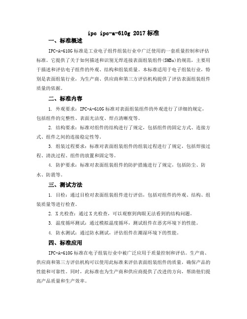
End joint width (C) is 75% width of component termination area (W) or 75% width of PB land (P), whichever is less.
Side overhang (A) causes minimum end joint width (C) requirements not to be met.
width. Fillet height covers terminal.
2021/10/10
Maximum side overhang (A) is 25%W.
Maximum side overhang (A) is 25%W.
End overhang (B) is not permitted.
單邊高翹
2021/10/10
23
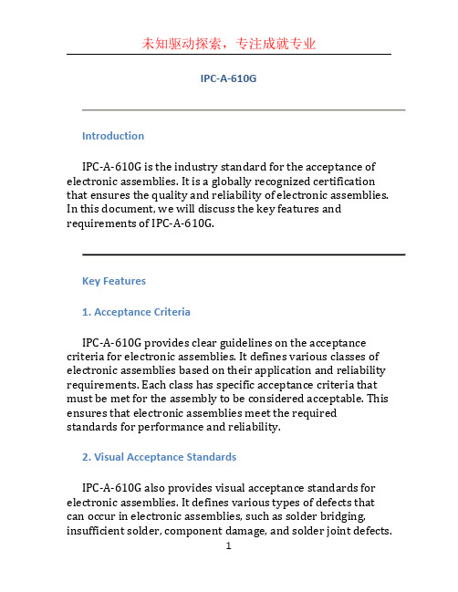
Travis M/B DIP component cosmetic
1.水平高翘,最大允许限度为0.3mm. 2.不允许單边高翘。
2021/10/10
24
Travis base sample
RAM 的卡勾不可出现变形等不良。
2021/10/10
25
Travis M/B DIP component cosmetic
不能出现任何标记,特 别是有铅异物。
2021/10/10
零件往錫墊寬邊(A)偏移, 但 零件本體金屬焊墊寬邊(W) 75%以上焊接於電路板錫墊上.
零件往錫墊寬邊(A)偏移, 但零 件本體不足75% 寬邊(C)以上焊 接於電路板錫墊上.
零件往錫墊長邊偏移(B).
No side overhang. Side joint length (D) equals component termination length.
ipc ipc-a-610g 2017标准
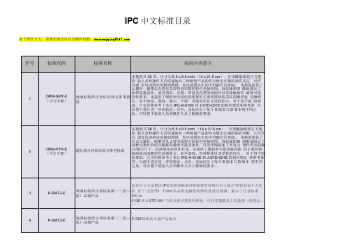
ipc ipc-a-610g 2017标准一、标准概述IPC-A-610G标准是工业电子组件组装行业中广泛使用的一套质量控制和评估标准。
它提供了关于如何描述和识别无焊连接表面组装组件(SMBs)的规范,主要用于描述和评估电子组件的外观、结构和组装质量。
本标准适用于电子组装行业,特别是表面组装行业,为生产商、供应商和第三方评估机构提供了评估表面组装组件质量的依据。
二、标准内容1. 外观要求:IPC-A-610G标准对表面组装组件的外观进行了详细的规定,包括组件的完整性、表面光洁度、焊点清晰度等。
2. 结构要求:标准对组件的结构进行了规定,包括组件的固定方式、连接方式、组件之间的连接稳定性等。
3. 组装过程要求:标准对表面组装组件的组装过程进行了规定,包括焊接过程、清洗过程、组件的放置和固定等。
4. 防护要求:标准对表面组装组件的防护措施进行了规定,包括防尘、防水、防震等。
三、测试方法1. 目检:通过目检对表面组装组件进行评估,包括对组件的外观、结构、组装质量等进行检查。
2. X光检查:通过X光检查,可以观察到肉眼无法看到的结构问题。
3. 温度循环测试:通过模拟温度循环,测试组件在恶劣环境下的性能。
4. 防水测试:通过防水测试,评估组件在潮湿环境下的性能。
四、标准应用IPC-A-610G标准在电子组装行业中被广泛应用于质量控制和评估。
生产商、供应商和第三方评估机构可以使用此标准来评估表面组装组件的质量,确保产品的性能和可靠性。
同时,此标准也为生产商和供应商提供了改进的方向,帮助他们提高产品质量和生产效率。
五、总结IPC-A-610G 2017标准是工业电子组装行业的重要标准,为生产商、供应商和第三方评估机构提供了评估表面组装组件质量的依据。
了解和掌握此标准,对于提高电子组装行业的产品质量和可靠性具有重要意义。
IPC-A-610G
IPC-A-610GIntroductionIPC-A-610G is the industry standard for the acceptance of electronic assemblies. It is a globally recognized certification that ensures the quality and reliability of electronic assemblies. In this document, we will discuss the key features and requirements of IPC-A-610G.Key Features1. Acceptance CriteriaIPC-A-610G provides clear guidelines on the acceptance criteria for electronic assemblies. It defines various classes of electronic assemblies based on their application and reliability requirements. Each class has specific acceptance criteria that must be met for the assembly to be considered acceptable. This ensures that electronic assemblies meet the required standards for performance and reliability.2. Visual Acceptance StandardsIPC-A-610G also provides visual acceptance standards for electronic assemblies. It defines various types of defects that can occur in electronic assemblies, such as solder bridging, insufficient solder, component damage, and solder joint defects.The standard provides criteria for evaluating these defects and determining whether they are acceptable or not.3. Workmanship StandardsIPC-A-610G defines the requirements for workmanship in the assembly of electronic components. It covers various aspects of workmanship, including component placement, soldering, cleaning, and testing. The standard ensures that the assembly process is carried out correctly and consistently, thereby reducing the risk of defects and failures.4. In-Process InspectionIPC-A-610G emphasizes the importance of in-process inspection during the assembly process. It provides guidelines for inspecting electronic assemblies at various stages of production to ensure that defects are detected and corrected early. This helps to identify and address any issues that may affect the quality and reliability of the final product.5. Reliability TestingThe standard also includes requirements for reliability testing of electronic assemblies. It specifies the test methods and criteria for evaluating the performance and durability of the assemblies under various conditions. Reliability testing ensures that the assemblies can withstand the expected operating environments and meet the required reliability standards.Benefits of IPC-A-610G1. Improved Quality and ReliabilityBy following the guidelines of IPC-A-610G, electronic assembly manufacturers can improve the quality and reliability of their products. The standard provides clear criteria for evaluating the acceptability of electronic assemblies, ensuring that only assemblies that meet the required standards are accepted. This reduces the risk of defects and failures in the field, leading to improved customer satisfaction.2. Consistency and StandardizationIPC-A-610G brings consistency and standardization to the electronic assembly industry. With a globally recognized standard in place, manufacturers can ensure that their processes and products adhere to industry best practices. This helps to eliminate variations in quality across different suppliers and provides customers with assurance that they are receiving a product of consistent quality.3. Cost SavingsFollowing the requirements of IPC-A-610G can lead to cost savings for electronic assembly manufacturers. By improving the quality and reliability of their products, manufacturers can reduce the number of field failures and warranty claims. This reduces the cost of repairs and replacements, resulting in significant cost savings in the long run.ConclusionIPC-A-610G is an important industry standard for the acceptance of electronic assemblies. It provides clear guidelines and acceptance criteria for evaluating the quality and reliability of electronic assemblies. By following the requirements of IPC-A-610G, manufacturers can improve the quality of their products, achieve consistency and standardization, and realize cost savings.。
表面贴装标准工艺IPC-A-610C

橢圓形腳, 圓形腳
允收:(合格) 元件腳偏移寬度最多 等于元件腳寬的1/2
拒收: 元件引腳不能伸出 焊盤
允收:(理想) 上錫寬度等于元件 腳寬
允收:(合格) 倒腳有適當的錫
允收:(理想) 上錫寬度等于元件 腳寬
允收:(合格)
拒收: 元件腳翹起
允收:(理想) 焊點光滑圓潤,界限清 晰,無漏焊,焊點飽滿,不 灰暗,不存在較明顯的 焊點間的差異 焊點定位直接,無漏焊 無焊球出現
允收:(合格) 焊點
拒收:
在X射線下有橋接的黑 點(倘若它們不是在 BGA下面的原因)
開路
漏焊
超過25%的球與板接口 未焊接上
允收:(合格) 少于10%的球與板接口未焊接
上錫高度可延伸, (理想)
元件腳寬位于焊盤中 間,沒有任何偏移
允收:(理想) 對于末端向下結構 的元件,上錫高度 (F))至少到引腳彎 曲處的終點
允收:(合格) 上錫高度F最小等 于焊錫厚度G加元 件腳厚度T的50%
允收:(合格)
元件腳偏移距離最大等 于元件腳寬的50%
拒收:
明顯的上錫 不足
允收:
端子貼于焊盤 且上錫良好
允收:(理想)
端子貼于焊盤中 間且
焊盤和端子明顯 上錫,側面上錫良 好
拒收:
焊盤和端子 沒有接觸
理想: 端子貼于焊盤中 央且沒有偏移
允收: 端子偏出焊盤而 偏移寬度A小于 焊盤或元件寬的 1/4
拒收: 元件超出焊盤或 元件寬的1/4
拒收: 端子超出焊盤
元件腳偏移焊盤的 距離最大等于元件 腳的一半,如果超 出則視為拒收.
IPC-A-610国际标准中英文对照(doc 17)

IPC-A-610国际标准中英文对照4.6.2 Heat sink-Contact散热片――接触片arget-Class 1,2,3目标——等级1,2,3· Component and heatsink are infull contact with themounting surface.组件和散热片与安装表面完全接触· Hardware meets specified attachment requirements.部件满足规定的接触要求。
Figure图4-641. Heat sink散热片Acceptable-Class 1,2,3可接受的——等级1,2,3· Component not flush.组件不平齐· Minimum 75% contact withmounting surface.至少有75%与安装表面接触· Hardware meets mountingtorque requirements ifspecified.如果有规定,部件满足安装的转距要求Figure图4-651. Gap2. Heat sink间隙散热片Defect-Class 1,2,3缺点——等级1,2,3· Component is not in contactwith mounting surface.组件没有接触到安装表面· Hardware is loose and can bemoved.部件松弛可以移动。
Figure图4-661. Heat sink2. Gap散热片间隙5.1 Orientation方向5.1.1 Orientation-Horizontal方向——水平Target-Class 1,2,3目标——等级1,2,3•Components are centered betweentheir lands.组件位于焊盘中央•Component markings arediscernible.组件标识清晰可见•Nonpolarized components are oriented so thatmarkings all read the same way (left-to-rightor top-to-bottom).Figure图5-1 无极性组件的方向应使其标识都能按同样方式进行辨识(从左到右或从上到下)Acceptable-Class 1,2,3可接受的——等级1,2,3•Polarized and multileadcomponents are orientedcorrectly.有极性和多引脚的组件应按正确方向安装。
IPC中文标准目录
可的可接受性标准带到你的培训室或检验区域。该海报共一张,适用于2级产品
6
P-PTH3-E
通孔焊点评估海报-3级产品
P-PTH2-E的3级产品版本。
7
P-MICRO
镀覆孔显微剖切图中的各种现象
被称为“噩梦般的显微剖切图”,这张24x36inch(60×90厘米)真彩海报确定了42种可在镀覆孔横截面上观察到的现象。非常清晰的图面为常见的(和不那么常 见)现象的讨论提供了支持。所有缺陷名称都与IPC-A-600,IPC-6012和IPC-T-
套包括三张海报,分别为片式、鸥翼形和J形引线元器件的2级要求。
4
P-SMT3-E
表面贴装焊点评估海报(一套三 张)-3级产品
P-SMT2-E的3级产品版本。
5
P-PTH2-E
通孔焊点评估海报-2级产品
这份“51×71cm”真彩海报以高品质电脑绘制图形,直观地定义了行业标准IPC-A-
610E和J-STD-001中规定的2级通孔焊接点最低/最高的可接受性要求。这份海报非常清晰地描述了复杂的通孔焊点要求,所有操作人员和检验员都容易理解和应
对湿度、回流焊敏感的表面贴装器件的处置、包装、发运及使用 方法
本标准向SMD制造商和用户提供了标准的表面贴装器件操作、包装、运输和使用方法。所提供的这些方法可避免由于吸收湿气和暴露在再流焊温度下造成的封装损伤,这些损伤会导致合格率和可靠性的降低。通过使用这些程序、以及采用能达到从密封之日算起在密封干燥袋内12个月最短保存期限的干燥包装工艺,即能实现安全无损的再流焊接。由IPC和JEDEC联合开发。全文共17页,于2005年
3
P-SMT2-E
ipc-610标准

ipc-610标准IPC-610标准是国际电子产业协会所制定的一项关于电子装配质量要求的标准。
该标准包含了关于电子组装的基本要求、接收标准、缺陷和判定等方面的内容。
IPC-610标准是电子制造商和质量控制人员必须遵循的指南,以确保他们生产的电子产品符合规定的质量标准。
IPC-610标准被广泛应用于电子制造行业,尤其是电子装配和焊接领域。
该标准对于电子组装和引线焊接的各个阶段,从原材料检查到最终装配,都提供了详细的质量要求和判定标准。
IPC-610标准的主要内容包括以下几个方面:1.产品分类:IPC-610标准将电子产品分为多个类别,根据其应用环境和关键性要求的不同进行分类。
2.缺陷标准:IPC-610标准列举了电子产品组装过程中可能出现的各种缺陷,如焊接不良、引线错位、器件损坏等。
对于每种缺陷,该标准都提供了详细的定义和判定依据。
3.接收标准:IPC-610标准规定了接收标准,并提供了对不同缺陷级别的判定标准。
根据产品的类别和重要性,制定了不同的可接受缺陷水平。
4.工艺要求:IPC-610标准中包含了一系列有关组装和焊接工艺的要求,如引线长度、焊接温度、保护层厚度等。
这些要求旨在确保组装的产品具有良好的连接性和可靠性。
除了以上几个方面,IPC-610标准还包含了关于清洁、防卫测量、抗静电保护等方面的详细要求。
该标准使用了丰富的图片和示意图,以便更好地说明各项要求。
IPC-610标准的应用范围非常广泛,涵盖了各种类型的电子产品,包括手机、电脑、电视机、汽车电子产品等。
通过遵循该标准,制造商和质量控制人员可以确保他们的产品在生产过程中符合相关的质量标准,从而提高产品的质量和可靠性。
总之,IPC-610标准是电子制造行业中非常重要的一项标准。
它为电子产品的组装和焊接提供了详细的质量要求和判定标准,帮助制造商和质量控制人员提高产品的质量和可靠性。
遵循IPC-610标准可以提高电子产品的质量,降低生产成本,并增加消费者的满意度。
- 1、下载文档前请自行甄别文档内容的完整性,平台不提供额外的编辑、内容补充、找答案等附加服务。
- 2、"仅部分预览"的文档,不可在线预览部分如存在完整性等问题,可反馈申请退款(可完整预览的文档不适用该条件!)。
- 3、如文档侵犯您的权益,请联系客服反馈,我们会尽快为您处理(人工客服工作时间:9:00-18:30)。
IPC-A-610国际标准中英文对照4.6.2 Heat sink-Contact散热片――接触片arget-Class 1,2,3目标——等级1,2,3· Component and heatsink are infull contact with themounting surface.组件和散热片与安装表面完全接触· Hardware meets specified attachment requirements.部件满足规定的接触要求。
Figure图4-641. Heat sink散热片Acceptable-Class 1,2,3可接受的——等级1,2,3· Component not flush.组件不平齐· Minimum 75% contact withmounting surface.至少有75%与安装表面接触· Hardware meets mounting torquerequirements ifspecified.如果有规定,部件满足安装的转距要求Figure图4-651. Gap2. Heat sink间隙散热片Defect-Class 1,2,3缺点——等级1,2,3· Component is not in contactwith mounting surface.组件没有接触到安装表面· Hardware is loose and can bemoved.部件松弛可以移动。
Figure图4-661. Heat sink2. Gap散热片间隙5.1 Orientation方向5.1.1 Orientation-Horizontal方向——水平Target-Class 1,2,3目标——等级1,2,3•Components are centeredbetween their lands.组件位于焊盘中央•Component markings arediscernible.组件标识清晰可见•Nonpolarized components are oriented so thatmarkings all read the same way (left-to-rightor top-to-bottom).Figure图5-1 无极性组件的方向应使其标识都能按同样方式进行辨识(从左到右或从上到下)Acceptable-Class 1,2,3可接受的——等级1,2,3•Polarized and multileadcomponents are orientedcorrectly.有极性和多引脚的组件应按正确方向安装。
•When hand formed andhand-inserted, polarization symbols are discernible.当手工成型及手插件时,极性符号可以辨识。
•All components are as specified and terminate toFigure图 5-2 correct lands.所有组件都符合规定并连接到正确的焊盘上。
•Nonpolarized components do not need to be oriented so that markin gs all read the same way(left-to right or top to-bottom).无极性的组件不需要按同样的方向,只要标识可按相同方向辨识即可(从左到右或从上到下).5.1.1 Orientation-Horizontal(cont.)方向——水平(续)Defect-Class 1,2,3缺点——等级1,2,3•Component is not as specified(Wrong part).组件不符合规定(组件错误)•Component not m ounted incorrect holes.组件没有安装在正确的孔中。
•Polarized component mounted backwards.有极性组件安装方向相反。
•Multileaded component not oriented correctly.Figure图 5-3 多引脚组件的安装方向不正确。
5.1.2 Orientation-Vertical方向——垂直Target-Class 1,2,3目标——等级 1,2,3•Nonpolarized componentmarkings read from the topdown.无极性组件的标识可以从上至下辨识•Polarized markings arelocated on top.极性标识位于顶部.Figure图 5-4Acceptable-Class 1,2,3可接受的——等级 1,2,3•Polarized part is mounted with a long ground lead.极性组件安装时有长的接地引脚•Polarized marking hidden.极性标识被隐藏起来•Nonpolarized component markings read from bottom to top.无极性组件标识可以从底至上辨识。
Figure图 5-5Defect-Class 1,2,3缺点——等级 1,2,3•Polarized component is mountedbackwards.极性组件安装反向。
Figure图 5-65.2 Mounting安装5.2.1 Mounting-Horizontal-Axial Leaded-Supported Holes安装——水平——轴向引脚——有支撑孔Target-Class 1,2,3目标——等级1,2,3•The entire body length of thecomponent is incontact with the boardsurface.整个组件本体长度与线路板表面完全接触•Components required to be mounted off the board are ,at least1.5mm[0.059 in]from the board surface; e.g., high heat dissipating. 需要离开线路板表面安装的组件至少要离开线路板Figure图 5-7 平面1.5mm(0.059 in),如高散热器件.Figure图 5-85.2.1Mounting-Horizontal-AxialLeaded-Supported Holes(cont.)安装——水平——轴对称引脚——有支撑孔Acceptable-Class 1,2可接受的——等级1,2,3•The maximum space between thecomponent and theboard surface does not violate the requirements forlead protrusion(see 5.2.7)or component height(H).Figure图 5-9 ((H) is auser-determined dimension.)组件与线路板平面之间的最大间距不应违反引脚突出(见5.2.7)或组件高度(H)的要求。
(高度(H)是由使用者决定的尺寸)Process Indicator-Class 3程序指示——等级3•The farthest distance between the component body and the board(D)is larger than 0.7mm[0.028 in].组件本体与线路板之间的最大的距离(D)超过0.7mm(0.028 in)。
Defect-Class 1,2,3缺点——等级1,2,3•Components required to be mounted above the board surface are lessthan 1.5mm[0.059 in]要求离开线路板表面安装的组件与线路板的距离小于1.5mm(0.059in).5.2.2 Mounting-Horizontal-AxialLeaded-Unsupported Holes安装——水平——轴向引脚——无支撑的孔Target-Class 1,2,3目标——等级 1.2.3•The entire body length of the component is incontact with the board surface.整个组件本体长度与线路板表面完全接触.•Components required to be mounted off the board areat minimum 1.5mm[0.059 in] from the boardFigure图 5-10 surface ;e.g. ,high heatdissipating.1.No Plating in barrel 需要离开线路板表面安装的组件至少要离开线路板平孔壁上没有电镀面1.5mm(0.059 in),如高散热器件.Components required to be mounted off the board are provided with lead forms at the board surface or other mechanical support to prevent lifting of solder land.需要离开线路板安装的组件在线路板表面利用引脚形状或其它机械支撑来防止焊盘的翘起。
Figure图 5-11 Figure图 5-121.Lead forms引脚形状Defect-Class 1,2,3缺点——等级1,2,3•Components required to bemounted off the board arenot provided with lead forms at the board surfaceor other mechanical support to prevent lifting ofsolder land.Figure图 5-13需要离开面板安装的组件在线路板表面未利用引脚的形状或其它机械支撑来防止焊盘翘起•surface Components required tobe mounted above the board areless than 1.5mm[0.059 in].要求离开线路板表面安装的组件与线路板的距离小于1.5mm(0.059in)Figure图 5-145.2.3Mounting-Horizontal-RadialLeaded安装——水平——径向引脚Target-Class 1,2,3目标——等级1,2,3•The component body is in flatcontact withthe board's surface.组件本体与线路板表面平贴接触• Bonding material is present, if required .See4.4.若需要,则可存在粘贴的物质,见4.4Figure图 5-15Acceptable-Class 1,2,3可接受的——等级1,2,3•Component in contact withboard on at least oneside and/or surface.组件与线路板至少有一边和/或面接触。