电容触摸屏QT703018EUPEa规格书
70寸触摸一体机产品规格书

魔方影音
-
Dolby解码
DD+
自动声音调整
●
2
端子
TV
1
视频输入
1(复合视频转接线)
TV USB输入
2(侧面*1前置*1)
PC USB输入
1(前置)
Touch USB输入
2(侧面*1前置*1)
音频输入)输入
1(复合视频转接线)
DVI输入/输出
1入/0出
OPS接口
70寸触摸一体机产品规格书
1
型号
LED70W20
外观
前壳(注明是否开模具)
铝合金型材
后壳(注明是否开模具)
钣金
底座
-
壁挂支架
一体化包装
扬声器
-
玻璃
5mm钢化玻璃
屏幕
背光光源
E-LED
屏幕尺寸
70
屏幕比例
16:9
分辨率
1920*1080
一键关屏
●
声音
平衡调节
●
五段式均衡器
●
DTS
●
SRS Trurround HD
3、RAM:1.5G;ROM:8GB
主要功能
结构一体化(内置触摸框、非外套)
支持android下触控(包括触控菜单)
可安装apk客户端
智能亮度感应(基于触摸下)
外挂电脑支持(安装于整机后壳)
红外遥控
6
1
HDMI输入
1(前置)
VGA输入/输出
1入/1出
音频输出
1(复合视频转接线)
视频输出
1(复合视频转接线)
SPDIF输出
1
红外输入
1
Unitronics SambaOPLC 3.5英寸、4.3英寸和7英寸平板颜色触摸屏PLC说明书
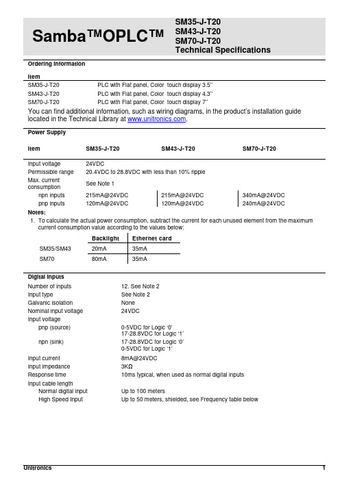
Samba™OPLC™ SM35-J-T20SM43-J-T20SM70-J-T20Technical SpecificationsOrdering InformationItemSM35-J-T20 PLC with Flat panel, Color touch display 3.5’’SM43-J-T20 PLC with Flat panel, Color touch display 4.3’’SM70-J-T20 PLC with Flat panel, Color touch display 7’’You can find additional information, such as wiring diagrams, in the product’s installation guide located in the Technical Library at .Power SupplyItem SM35-J-T20 SM43-J-T20 SM70-J-T20Input voltage 24VDCPermissible range 20.4VDC to 28.8VDC with less than 10% rippleMax. currentconsumptionSee Note 1npn inputs 215mA@24VDC 215mA@24VDC 340mA@24VDCpnp inputs 120mA@24VDC 120mA@24VDC 240mA@24VDCNotes:1. To calculate the actual power consumption, subtract the current for each unused element from the maximumcurrent consumption value according to the values below:Backlight Ethernet cardSM35/SM43 20mA 35mASM70 80mA 35mADigital InputsNumber of inputs 12. See Note 2Input type See Note 2Galvanic isolation NoneNominal input voltage 24VDCInput voltagepnp (source) 0-5VDC for Logic ‘0’17-28.8VDC for Logic ‘1’npn (sink) 17-28.8VDC for Logic ‘0’0-5VDC for Logic ‘1’Input current 8mA@24VDCInput impedance 3KΩResponse time 10ms typical, when used as normal digital inputsInput cable lengthNormal digital input Up to 100 metersHigh Speed Input Up to 50 meters, shielded, see Frequency table below2/15 Samba™ OPLC™High speed inputs Specifications below apply when wired as HSC/shaft-encoder.See Note 2Frequency (max) See Note 3Cable length (max.) HSC Shaft-encoder10m 30kHz 20kHz25m 30kHz 13kHz50m 25kHz 9kHzDuty cycle 40-60%Resolution 32-bitNotes:2. This model comprises a total of 12 inputs. Input functionality can be adapted as follows:12 inputs may be used as digital inputs. They may be wired, in a group, and set to eithernpn or pnp via a single jumper.In addition, according to jumper settings and appropriate wiring:Inputs 10 and 11 can function as either digital or analog inputs.Inputs 0, 2, and 4 can function as high-speed counters, as part of a shaft-encoder,or as normal digital inputs.Inputs 1, 3, and 5 can function as either counter reset, as part of a shaft-encoder,or as normal digital inputs.If inputs 0, 2, 4 are set as high-speed counters (without reset), inputs 1, 3, 5can function as normal digital inputs.3. pnp/npn maximum frequency is at 24VDC.Analog InputsNumber of inputs 2, according to wiring as described above in Note 2Input type Multi-range inputs: 0-10V, 0-20mA, 4-20mAInput range 0-20mA, 4-20mA 0-10VDCInput impedance 243Ω>150KΩMaximum input rating 25mA, 6V 15VGalvanic isolation NoneConversion method Successive approximationResolution (except 4-20mA) 10-bit (1024 units)Resolution (at 4-20mA) 204 to 1023 (820 units)Conversion time One configured input is updated per scan. See Note 4Precision 0.9%Status indication Yes – if an analog input deviates above the permissible range,its value will be 1024.Note:4. For example, if 2 inputs are configured as analog, it takes 2 scans to update all analog values.SMxx-J-T20 Technical Specifications 2/15Digital OutputsNumber of outputs 8 transistor pnp (source)Output type P-MOSFET (open drain)Isolation NoneOutput current (resistive load) 0.5A maximum per output3A maximum total per commonMaximum frequency 50Hz (resistive load)0.5Hz (inductive load)PWM maximum frequency 0.5KHz (resistive load). See Note 5Short circuit protection YesShort circuit indication Via softwareOn voltage drop 0.5VDC maximumPower supply for outputsOperating voltage 20.4 to 28.8VDCNominal voltage 24VDCNote:5. Outputs 0 to 6 can be used as PWM outputs.Graphic Display ScreenItem SM35-J-T20 SM43-J-T20 SM70-J-T20 LCD Type TFT, LCD display TFT, LCD display TFT, LCD display Illumination backlight White LED White LED White LED Display resolution 320x240 pixels 480x272 pixels 800x480 pixels Viewing area 3.5" 4.3" 7"Colors 65,536 (16-bit) 65,536 (16-bit) 65,536 (16-bit) Touchscreen Resistive, analog Resistive, analog Resistive, analog Screen brightness control Via software (Store value to SI 9, values range: 0 to 100%)Virtual Keypad Displays virtual keyboard when the application requires data entry.ProgramItem SM35-J-T20 SM43-J-T20 SM70-J-T20 Memory sizeApplication Logic 112KB 112KB 112KBImages 1MB 2MB 5MBFonts 512KB 512KB 512KBOperand type Quantity Symbol ValueMemory Bits 512 MB Bit (coil)Memory Integers 256 MI 16-bit signed/unsignedLong Integers 32 ML 32-bit signed/unsignedDouble Word 32 DW 32-bit unsignedMemory Floats 24 MF 32-bit signed/unsignedFast Bits 64 XB Fast Bits (coil) – not retainedFast Integers 32 XI 16 bit signed/unsigned (fast, not retained)Fast Long Integers 16 XL 32 bit signed/unsigned (fast, not retained)Fast Double Word 16 XDW 32 bit unsigned (fast, not retained)Timers 32T Res. 10 ms; max 99h, 59 min, 59.99sCounters 16 C 32-bitData Tables 32K dynamic data (recipe parameters, datalogs, etc.)16K fixed data (read-only data, ingredient names, etc)HMI displays Up to 24Program scan time 15µs per 1kb of typical application2/15 Samba™ OPLC™Communication PortsPort 1 1 channel, RS232 (SM35) , USB device (SM43/SM70)Galvanic isolation SM35 and SM43 – NoSM70 - YesBaud rate 300 to 115200 bpsRS232 (SM35 only)Input voltage ±20VDC absolute maximumCable length 15m maximum (50’)USB device (SM43,SM70 only)Port type Mini-BSpecification USB 2.0 complaint; full speedCable USB 2.0 complaint; up to 3mPort 2 (optional) See Note 6CANbus (optional) See Note 6Notes:6. The user may order and install one or both of the following modules:- A serial RS232/RS485 isolated/non-isolated interface module, or an Ethernet Interface module in port 2.- A CANbus modulemodules documentation is available on the Unitronics website.MiscellaneousClock (RTC) Real-time clock functions (date and time)Battery back-up 7 years typical at 25°C, battery back-up for RTC and system data, includingvariable dataBattery replacement Yes. Coin-type 3V, lithium battery, CR2450DimensionsItem SM35-J-T20 SM43-J-T20 SM70-J-T20Size 109 x 114.1 x 68mm(4.29 x 4.49 x 2.67”).See Note 7 136 x 105.1 x 61.3mm(5.35 x 4.13 x 2.41”).See Note 7210 x 146.4 x 42.3mm(8.26 x 5.76 x 1.66”).See Note 7Weight 205g (7.23 oz) 344g (12.13 oz) 633g (22.32 oz) Notes:7. For exact dimensions, refer to the product’s Installation Guide.EnvironmentOperational temperature 0 to 50ºC (32 to 122ºF)Storage temperature -20 to 60ºC (-4 to 140ºF)Relative Humidity (RH) 10% to 95% (non-condensing)Mounting method Panel mounted (IP65/66/NEMA4X)DIN-rail mounted (IP20/NEMA1)Operating Altitude 2000m (6562 ft)Shock IEC 60068-2-27, 15G, 11ms durationVibration IEC 60068-2-6, 5Hz to 8.4Hz, 3.5mm constant amplitude,8.4Hz to 150Hz, 1G acceleration.SMxx-J-T20 Technical Specifications 2/15 The information in this document reflects products at the date of printing. Unitronics reserves the right, subject to all applicable laws, at any time, at its solediscretion, and without notice, to discontinue or change the features, designs, materials and other specifications of its products, and to either permanently ortemporarily withdraw any of the forgoing from the market.All information in this document is provided "as is" without warranty of any kind, either expressed or implied, including but not limited to any implied warranties of merchantability, fitness for a particular purpose, or non-infringement. Unitronics assumes no responsibility for errors or omissions in the information presented inthis document. In no event shall Unitronics be liable for any special, incidental, indirect or consequential damages of any kind, or any damages whatsoever arising out of or in connection with the use or performance of this information.The tradenames, trademarks, logos and service marks presented in this document, including their design, are the property of Unitronics (1989) (R"G) Ltd. or other third parties and you are not permitted to use them without the prior written consent of Unitronics or such third party as may own them.DOC17017-A8 02/15。
SIMATIC MULTIPANEL MP370 15英寸彩色TFT触摸屏显示器商品说明书
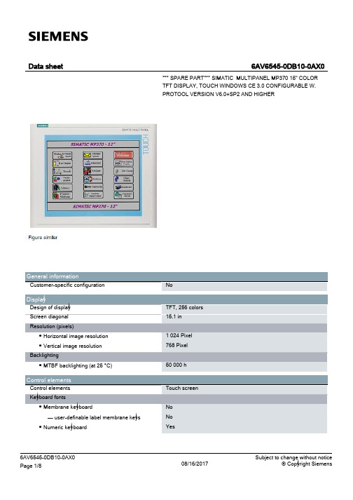
Touch screen
No No Yes
6AV6545-0DB10-0AX0 Page 1/8
08/16/2017
Subject to change without notice © Copyright Siemens
● alphanumeric keyboard ● hexadecimal keyboard ● Multi-key operation
6AV6545-0DB10-0AX0 Page 2/8
08/16/2017
Subject to change without notice © Copyright Siemens
Error LED
Time of day Clock ● Type ● retentive ● synchronizable
Installation type/mounting Mounting position maximum permissible angle of inclination without external ventilation
Supply voltage Type of supply voltage UPS connectable (serial)
IP65 IP20
CE, FM Class I Div. 2, cULus, EX Zone 2/22, C-TICK
0 °C 50 °C -20 °C 60 °C 85 %
Windows CE
ProTool Version 6 SP 2 or higher, or WinCC flexible Standard Version 2004 or higher (to be ordered separately)
7030说明书

校驗及校正聲明奧斯達儀器股份有限公司特別聲明,本操作使用手冊所列的儀器設備完全符合本公司一般型號上所標稱的規範和特性。
本儀器在出廠前已經通過本公司的廠內校驗。
本公司校驗用的所有儀器設備都已委請中央標準局認可的檢驗中心作定期校正,校驗的程式和步驟是符合電子檢驗中心的規範和標準。
産品品質保證奧斯達儀器股份有限公司保證所生産製造的新品機器均經過嚴格的品質確認,同時保證在出廠一年內,如有發現産品的製造瑕疵或零件故障,本公司負責免費給予修復。
但是如果使用者有自行更改電路、功能、或進行修理機器及零件或外箱損壞等情況,本公司不提供免費保修服務,得視實際狀況收取維修費用。
如果未按照規定將所有地線接妥或未按照安全規範操作機器而發生異常狀況,本公司恕不提供免費保修服務。
本保證不含本機器的附屬設備等非奧斯達電子所生産的附件在一年的保修期內,請將故障機組送回本公司維修中心或本公司指定的經銷商處,本公司會予以妥善修護。
如果本機組在非正常的使用下、或人爲疏忽、或非人力可控制下發生故障,例如地震、水災、暴動、或火災等非人力可控制的因素,本公司不予免費保修服務。
目錄第一章安全規定-------------------------3 第二章安規介紹-------------------------7 第三章技術指標-------------------------13 第四章面板/背板說明------------------- 16 第五章測試參數的設定-------------------19 第六章顯示訊息------------------------29 第七章操作程式及步驟-----------------35WARNING CAUTION 第一章:安全規定測試前應該仔細閱讀以下規定!!!1.1 一般規定使用本交流接地電阻測試儀器前,請認真閱讀該使用說明書,按說 明書要求使用。
在開啓本機的輸入電源開關前,請先選擇正確的輸入電壓(115V/230V)規格。
236英寸电容触摸平板技术规格书
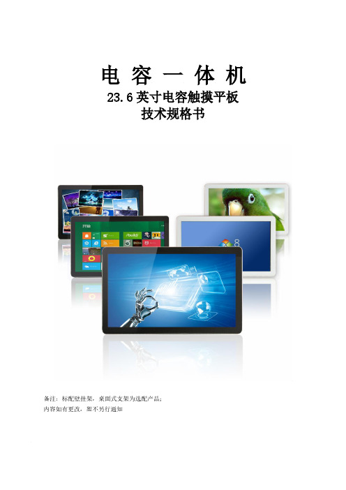
电容一体机23.6英寸电容触摸平板技术规格书(型号:HBY-D236)备注:标配壁挂架,桌面式支架为选配产品;内容如有更改,恕不另行通知一、产品特性1.结构设计:(1)纯平面结构,人体工程学设计,纤巧美观、流线造型、工艺精良;(2)显示、触控、PC系统一体化超薄设计,仅厚43 mm;2.使用效果:(1)采用最新研发的投射式电容屏,完美10点触摸,支持手写及多点手势;(2)触摸速度小于3ms,精确度好,使用简单便捷、易于维护;(3)抗光干扰,确保操作的准确性(强光直射照常使用);3.扩充性好:配置灵活,可扩充安装客户需求的各种功能配件;4.安全性高:铝合金+钣金结构,无锐利边缘,耐磨防腐烤漆工艺,整体防暴设计;5.性能稳定:先进的设计理念,严格的生产工艺,产品品质稳定可靠,故障率低;6.安装简便:通电一键开关机,免除现场安装调试。
二、系统设计三、液晶屏参数四、触摸屏参数五、显示参数 (仅做为触摸显示器部分使用)六、电源参数七、工作环境八、随机附件九、电脑参数十、物理规格屏幕23.6寸(对角线603.6mm)有效显示尺寸525.5×297 mm (16:9)整机尺寸(宽×高×厚)576(宽)×352(高)× 43(厚)mm 包装尺寸(宽×高×厚)635(宽)× 445(高)×140(厚)mm 底架标配壁挂架(净重0.78kg),可选配底座背部壁挂与机器连接的孔100×100 mm位尺寸(长×宽)壁挂螺丝规格M4净重(裸机)触显7.23 kg,一体机7.75kg毛重(包装)9.11 kg十一、整机结构图十二、产品细节图十三、产品款式/产品效果图十四、整机实拍图十五、产品配件图。
触摸屏ITO玻璃规格书

触摸屏ITO透明导电玻璃规格书客户:牧東光電(蘇州)有限公司规格:TKHTP(Chemical Tempered Glass/D-SiO2)发行日期:2008年9月1日编号:TK20080901-2所附说明是规格书中的一部分。
关于其中提到的生产过程和制造技术方面的信息已经被确认过,并保留了长信公司自身的特性。
长信保留根据需要更改一些技术方面信息的权利。
采购规格书(修订履历)触摸屏ITO透明导电玻璃规格书SPEC. NO. TK20080901-21.0概述1.1此说明书介绍了长信公司生产的触摸屏ITO透明导电玻璃和基片的主要特性。
1.2它适用于触摸屏ITO透明导电玻璃的生产过程和质量监控以及售后服务过程。
2.0产品品名及规格长信公司可提供以下规格触摸屏透明导电玻璃产品。
3.0 玻璃基片规格质量要求基片尺寸、公差及相应的检测方法如下。
4.0ITO玻璃质量要求质量保证区域为距玻璃四周边缘5mm以外的区域。
电阻保证区域为距玻璃四周边缘10mm以外的区域。
4.1 ITO玻璃表观质量4.2 ITO玻璃镀膜质量要求4.3ITO膜层稳定性5.0 质量保证5.1长信公司于2003年6月份通过ISO9001:2000质量体系认证,并与2006年11月份通过ISO14001:2004环境管理体系认证。
5.2长信公司在供货时提供出厂质量检验报告和产品合格证。
5.3抽样计划:请参考如下表格。
5.4质量问题的处理客户可以按照以下表格参数做IQC检测以认证长信公司产品对于在IQC认证中或客户生产过程中发现不合格品经过本公司确认后在双方达成协商情况下进行处理。
6.0 包装和标识6.1长信公司按客户的要求进行包装。
6.2 每片玻璃用间隔纸隔开,以防止玻璃之间相互滑动所造成膜面和玻璃的划痕。
6.3产品要求包装成小包,上下夹以硬纸板,并用热塑膜热缩包装。
6.4玻璃小包装和成品装箱数量如下:6.5标识说明6.5.1 小包装标识说明每包小包装上印有产品品名、生产批号、包号、数量、检验号和膜面指示章。
ELAN EM78F811N 8位微控制器 产品规格书说明书
产品规格书版本1.5义隆电子股份有限公司2021.07商标告之:IBM 为一个注册商标,PS/2是IBM 的商标之一。
Windows 是微软公司的商标。
ELAN 和ELAN 标志是义隆电子股份有限公司的商标。
版权所有 © 2021义隆电子股份有限公司所有权利保留台湾印制本规格书内容如有变动恕不另作通知。
关于该规格书的准确性、适当性或者完整性,义隆电子股份有限公司不承担任何责任。
义隆电子股份有限公司不承诺对本规格书之内容及信息有更新及校正之义务。
本规格书的内容及信息将为符合确认之指示而变更。
在任何情况下,义隆电子股份有限公司对本规格书中的信息或内容的错误、遗漏,或者其它不准确性不承担任何责任。
由于使用本规格书中的信息或内容而导致的直接,间接,特别附随的或结果的损害,义隆电子股份有限公司没有义务负责。
本规格书中提到的软件(如果有),都是依据授权或保密合约所合法提供的,并且只能在这些合约的许可条件下使用或者复制。
义隆电子股份有限公司的产品不是专门设计来应用于生命维持的用具,装置或者系统。
义隆电子股份有限公司的产品不支持而且禁止在这些方面的应用。
未经义隆电子股份有限公司书面同意,任何个人或公司不得以任何形式或方式对本规格书的内容之任一部分进行复制或传输。
义隆电子股份有限公司 总公司:地址: 30076新竹科学工业园区创新一路12号电话: +886 3 563-9977 传真: +886 3 563-9966 *****************.tw http :// 香港分公司:义隆电子(香港)股份有限公司 地址:九龙观塘巧明街95号世达 中心19楼A 室电话: +852 2723-3376 传真: +852 2723-7780美国:Elan InformationTechnology Group (U.S.A.) 地址: 10268 Bandley Drive Suite 101 , Cupertino , CA 95014,USA 电话: +1 408 366-8225 传真: +1 408 366-8225深圳分公司:义隆电子(深圳)有限公司地址:518057深圳市南山区高新技术产业园南区高新南六道迈科龙大厦8A电话: +86 755 2601-0565 传真: +86 755 2601-0500 ******************.cn上海分公司:义隆电子(上海)有限公司地址:上海市浦东新区盛荣路88弄3号703室(盛大天地源创谷内)电话:+86 21 5080-3866 ******************.cn目录目录1 综述 (1)2 特性 (1)3 引脚配置 (2)3.1 10-Pin MSOP (2)3.2 16-Pin DIP/SOP (2)3.3 14-Pin SOP (2)4 引脚描述 (3)5 系统概述 (5)5.1 内存图 (5)5.2 模块图 (6)6 功能描述 (7)6.1 操作寄存器 (7)6.1.1 R0:IAR (间接寻址寄存器) (7)6.1.2 R1 :TCC(定时器时钟) (7)6.1.3 R2:PC (程序计数器和堆栈) (7)6.1.4 R3 :SR(状态寄存器) (10)6.1.5 R4 :RSR(RAM选择寄存器) (10)6.1.6 Bank 0 R5 ~ R6, R8 (Port 5 ~ Port 6, Port 8) (10)6.1.7 Bank 0 R9:TBLP (指令TBRD表指针寄存器) (11)6.1.8 Bank 0 RA:WUPC (唤醒控制寄存器) (11)6.1.9 Bank 0 RB:EECR (EEPROM控制寄存器) (12)6.1.10 Bank 0 RC: EEPA (128 字节 EEPROM 地址) (12)6.1.11 Bank 0 RD: EEPD (128字节EEPROM 数据) (12)6.1.12 Bank 0 RE: OMCR (模式选择寄存器) (12)6.1.13 Bank 0 RF: ISR1 (中断状态寄存器 1) (15)6.1.14 R10 ~ R3F (15)6.1.15 Bank 1 R5~R7 (16)6.1.16 Bank 1 R8 (IRC 选择寄存器) (16)6.1.17 Bank 1 R9: TM1CR1 (定时器/计数器 1控制寄存器1) (16)6.1.18 Bank 1 RA: TM1CR2(定时器/计数器 1控制寄存器 2) (17)6.1.19 Bank 1 RB: TM1DAH (定时器/计数器 1数据缓冲A高字节) (18)6.1.20 Bank 1 RC: TM1DAL (定时器/计数器 1数据缓冲A低字节) (18)6.1.21 Bank 1 RD: TM1DBH (定时器/计数器 1数据缓冲B高字节) (18)6.1.22 Bank 1 RE: TM1DBL (定时器/计数器 1数据缓冲B低字节) (18)6.1.23 Bank 1 RF: ISR2 (中断状态寄存器 2) (19)6.1.24 Bank 2 R5:AISR (ADC输入选择寄存器) (19)6.1.25 Bank 2 R6: ADCON (A/D控制寄存器) (20)6.1.26 Bank 2 R7: ADCON2 (A/D控制寄存器2) (21)6.1.27 Bank 2 R8 : ADDH (AD高 8位数据缓存) (22)6.1.28 Bank 2 R9 : ADDL (AD低4位数据缓存) (22)6.1.29 Bank 2 RA: URCR (UART控制寄存器) (22)6.1.30 Bank 2 RB: URS (UART 状态寄存器) (23)6.1.31 Bank 2 RC: URTD (UART 发送数据缓冲寄存器) (24)6.1.32 Bank 2 RD: URRDL (UART 接收数据低位缓冲寄存器) (24)目录6.1.33 Bank 2 RE: URRDH (UART 接收数据高位缓冲寄存器) (24)6.1.34 Bank 2 RF (24)6.1.35 Bank 3 R5 (24)6.1.36 Bank 3 R6 : TBHP(指令TBRD的表指针寄存器) (24)6.1.37 Bank 3 R7: CMP2CON(比较器2控制寄存器) (25)6.1.38 Bank 3 R8 ~ RC (25)6.1.39 Bank 3 RD :TC3CR (定时器3控制) (25)6.1.40 Bank 3 RE :TC3D (定时器 3 数据缓存) (27)6.1.41 Bank 3 RF (27)6.2 特殊功能寄存器 (28)6.2.1 A (累加器) (28)6.2.2 CONT (控制寄存器) (28)6.2.3 IOC5 ~ IOC6, IOC8 (I/O端口控制寄存器) (28)6.2.4 IOC7, IOC9 (28)6.2.5 IOCA:WDTCR (WDT 控制寄存器) (29)6.2.6 IOCB: P6PDCR (下拉控制寄存器2) (29)6.2.7 IOCC: P6ODCR (漏极开路控制寄存器) (30)6.2.8 IOCD: P9PHCR (上拉控制寄存器2) (30)6.2.9 IOCE:IMR2 (中断屏蔽寄存器2) (31)6.2.10 IOCF: IMR1(中断屏蔽寄存器1) (31)6.3 TCC/WDT 与预分频器 (33)6.4 I/O 端口 (34)6.4.1 使用端口6输入状态改变唤醒/中断功能 (36)6.5 复位和唤醒 (37)6.5.1 复位 (37)6.5.2 总结唤醒和中断模式操作 (39)6.5.3 寄存器初始值的总结 (42)6.5.4 状态寄存器的T和P状态 (49)6.6 中断 (50)6.7 数据EEPROM (52)6.7.1 数据EEPROM控制寄存器 (52)6.7.2 编程步骤 / 举例示范 (52)6.8 模拟数字转换器(ADC) (53)6.8.1 A/D 取样时间 (53)6.8.2 A/D 转换时间 (54)6.8.3 睡眠期间的A/D转换 (54)6.8.4 编程步骤/注意事项 (55)6.9 定时器/计数器1 (TM1) (58)6.9.1 定时器/计数器模式 (58)6.9.2 窗口模式 (59)6.9.3 捕捉模式 (60)6.9.4 可编程分频输出模式和脉冲宽度调制模式 (62)6.9.5 蜂鸣器 (63)6.10 定时器/计数器3 (63)6.11 UART (65)6.11.1 UART 模式 (66)6.11.2 发送 (67)目录6.11.3 接收 (67)6.11.4 波特率发生器 (68)6.11 .5 UART 时序 (68)6.12 比较器 (69)6.12.1 外部参考信号 (69)6.12.2 内部参考电压 (70)6.12.3 比较器输出 (70)6.12.4 中断 (70)6.12.5 从睡眠至唤醒 (70)6.12.6 比较器初始化步骤 (71)6.13 振荡器 (71)6.13.1 振荡模式 (71)6.13.2 晶振 / 陶瓷谐振器(晶体) (72)6.13.3 外部RC振荡模式 (73)6.13.4 内部 RC 振荡模式 (74)6.14 代码选项寄存器 (75)6.14.1 代码选项寄存器 (Word 0) (75)6.14.2 代码选项寄存器(Word 1) (77)6.14.3 客户ID寄存器(Word 2) (78)6.15 上电注意事项 (79)6.16 外部上电复位电路 (79)6.17 残留电压保护 (80)6.18 指令集 (81)7片上调试系统(OCDS) (84)7.1 片上调试的限制 (84)8 时序图 (85)9 绝对最大额定参数 (86)10 DC电气特性 (87)11 AC电气特性 (92)A 编码与制造信息 (93)B 封装类型 (94)C 封装结构 (95)C.1 EM78F811NMS10 (95)C.2 EM78F811NSO14 (96)C.3 EM78F811NAD16 (97)C.4 EM78F811NASO16A (98)D 品质保证和可靠性 (99)D.1 地址缺陷检测 (99)目录规格修订历史目录用户应用注意事项(使用此IC前,应注意如下描述的注意事项,它包含重要信息)1. 如果IRC频率从A频率变为B频率,MCU需要等待一些时间才可以工作。
北京英博有源滤波触摸屏产品说明书版本_V2.0

动态滤波补偿控制器LSVG-2000产品说明指南版本号V2.0目录1.产品说明 (1)1.1.使用要点 (1)1.2.安全守则 (1)1.3.使用条件 (1)2.产品外形与端子定义 (2)2.1.产品外形尺寸 (2)2.2.端子定义 (3)3.LSVG-2000界面结构与说明 (4)3.1LSVG-2000界面结构 (4)3.2LSVG-2000界面说明 (4)4.LSVG-2000通讯功能 (17)附录LSVG-2000与上位机通讯点表 (18)1.产品说明1.1.使用要点本说明书旨在帮助您安全、规范的操作使用控制器在安装和操作控制器之前,请仔细阅读以下事项。
本手册供安装、维护和操作的人员使用。
1.2.安全守则1)不要打开控制器的外壳,因为控制器内部没有可以由用户来维护的部件。
2)不要将本产品用于除原目的以外的其他用途。
1.3.使用条件●海拔高度:海拔1500米以下●环境温度:-10~+40℃●相对湿度:最湿月的月平均最大相对湿度为90%,同时该月的月平均最低温度为25℃时表面无凝露●使用场所:不得有易燃、易爆、腐蚀性气体和液体等危险产品●地震烈度:6级以下●污秽等级:Ⅲ级以下注:其它特殊使用场合、环境条件可定制。
2.产品外形与端子定义2.1.产品外形尺寸LSVG-2000尺寸如表1所示:表1产品尺寸位置长(mm)宽(mm)深(mm)总体226.516336前面板226.51636后面板21315030机柜开孔215152-图1触摸屏外形尺寸图2.2.端子定义触摸屏供电电源为直流24V、1A,配备有专用的电源接口;触摸屏的USB接口为程序维护端口,仅供内部程序更新使用;触摸屏DB9接口包含了1个备用端口(COM1),2个485端口(COM2/COM3)。
表2端子口说明3.LSVG-2000界面结构与说明3.1LSVG-2000界面结构LSVG-2000界面显示结构框图如图2所示,总体由7个部分组成,分别为主画面、运行状态、报警信息、谐波分析、波形显示、专家参数以及用户登录。
- 1、下载文档前请自行甄别文档内容的完整性,平台不提供额外的编辑、内容补充、找答案等附加服务。
- 2、"仅部分预览"的文档,不可在线预览部分如存在完整性等问题,可反馈申请退款(可完整预览的文档不适用该条件!)。
- 3、如文档侵犯您的权益,请联系客服反馈,我们会尽快为您处理(人工客服工作时间:9:00-18:30)。
Power Electronics Ltd Specification for ApprovalCustomer:__Product name:Capacitive Touch Screen ModuleModel:QT703018EUPEaVersion: Ver01Customer Approval: __________________________Approved by Reviewed by Prepared byPower Electronics LtdRm. A&F,7/F,150 Dongyuan Rd,Shenzhen,China.Phone :( 86) 755 61692426Fax: (86)755 61692423Email:kelvin.ho@pel.hk <kelvin.ho@pel.hk>Product SpecificationD OC.V ERSION 1.0Power Electronics LtdMay 2010Specification Revision RecordNo Version Date Summary of changes Page 1Ver01 Newly CreatedRemarks:Index1. Features (4)2. Appearance Inspection (5)2.1 Inspection Conditions (5)2.2 Appearance Criteria (5)3. Cover Lens Process (7)4. Model (7)5. Electrical Characteristics (7)6. Reliability (8)7. Durability (9)8. Application Guide (10)8.1 Environment (10)8.2 Block diagram (10)8.3 Hardware Connect (10)8.4 Communication protocol and calibration (11)8.5 Read data(ChaCha to Host) (11)8.6 Mode switch (13)9 Important items of motions (16)10. Handing precautions (17)11 Structure chart (18)1. FeaturesItem Contents UnitType Projective Capacitive Multi-touchTP size (inch) 7.0’’Outline Dimension(Cover)164.9 X104.34 mmViewing Area 155.3 X 94.34 mm Active Area 152.4 X 91.44 mm Interface I2COperation Voltage 2.8V ~ 5.5VCurrent Consumption @3.0V, @25℃<0.4mA@sleep Mode, , <2mA @ Watch Mode <4mA@ Active Mode, <5mA@ Fast ModeScan rate 0Hz@sleep Mode, , ~10Hz@ Watch Mode,~40Hz@ Active Mode,~100Hz@ Fast Mode /panelCalibration mode Calibrate for noise environment changes (within 400m seconds)Resolution >500 dpiInput force <10gInput method Finger or exclusive pen Transparency >85%Surface hardness >7HScope This specification applies for finger input transparent touch panel.(These mentioned in the individual specification shall be given priority.)Application The product is touch panels used as the input devices for general electric appliances and OA equipment.2. Appearance Inspection;DisregardNote:Each test shall be done at a normal condition (23℃60%RH) unless otherwise specified separately.3. Cover Lens ProcessItem Contents Compression Resistance400 ~ 500 mPAChemistry Strengthen8 ~ 12 um / potassium ion Hardness>7H4. ModelConstruction Materials used remarkFirst Layer Cover Glass Thickness:1.5 mm Second Layer UV-Curing Thickness:0.15mm Third Layer ITO Glass Thickness:0.55mm5. Electrical CharacteristicsItem Specifications ESD (Machine model)±300V 200pF, 0 Ω, 5 timesESD (Human body model) ±1000V, 100pF, 1500Ω, 5 times ESD touching surface(Contacted)4KV, 100pF, 1500Ω, 5 times ESD touching surface (Air-discharge) 10KV, 100pF, 1500Ω, 5 timesItem Description Unit Supply Voltage from VDD to VSS-0.5 ~ 7.0 V Voltage from any pin to VSS-0.5 ~ 7.0 V Chip level ESD (HBM test) 26. ReliabilityItem Specification RemarksOperating temperature andhumidity -10~60℃,20~85% RHExcept for dewgatheringStorage temperature andhumidity -20~70℃,20~85% RHExcept for dewgatheringHumidity resistance 85% RH, 240H Except for dew gatheringHeat resistance 70℃,240H Except for dew gatheringCold resistance -20℃,240H Except for dew gatheringThermal shock -20℃(0.5hour)-70℃(0.5hour)by 50 cyclesExcept for dewgatheringVibration resistance 20 m/s2,10Hz to 55Hz(1min)is given for 30 mins.each in the directions ofX,Y,Z.Except for dewgatheringHumidity resistance The requirement in 4 shall besatisfied after exposing at60℃,90% RH for 240 hoursand normal temperature andhumidity for 24 hours.Except for dewgatheringHeat resistanceThe requirements in 4 shallbe satisfied after exposing at70℃,for 240 hours and atnormal temperature andhumidity for 24 hours.Except for dewgatheringCold resistanceThe requirements in 4 shallbe satisfied after exposing at-20℃, for 240 hours and atnormal temperature andhumidity for 24 hours.Except for dewgatheringNote:1:The reliability test shall be done with the touch panel put on a clean, flat board, and with the circuit open.2:Test environment must be clean room, class 10k or higher, make sure there is no crack, scratch, or foreign objects8. Application Guide8.1 EnvironmentItem Specification Remarks thermometer -10~60ºChumidity 20~85% RH8.2 Block diagramIC Pin ConfigurationPin NO Pin name Description1 NC2 SDA I2C DATA3 SCL I2C Clock4 GND Ground Connection5 VDD Supply voltage VDD:5V6 NC7 NC8 RST Reset pin9 ATTN ATTN line8.3 Hardware ConnectHost MCU can be use i2c interface to communicate with ChaCha, the SDA ,SCK and ATTN pin also need a pull up resistor to maintain the I2C bus voltage status.8.4 Communication protocol and calibrationThe touch panel uses the I2C communication protocols, the HOST must set the clock to 100khzPlease open the exterior interrupt,and prepare a falling edge interruptThe objective of the calibration is to measure the capacitance offsets and the noise offset of the electrode system when no finger is touching, and to store these values into EEPROM.After power on,the calibration must be done when we use the ITO panel at the first time, The HOST will pull low the ATTN line,then the HOST will send the command as follows in 3.8 ms to calibrate.After the command was sent,the HOST will release the ATTN line,that the ATTN line will return high ,then ChaCha will complete calibration in 500ms,during the 500ms,the HOST will not send any command.After the calibration be done,the HOST must clear the register, the command as follow:NOTE:There must be no finger on the ITO panel during the calibrationAfter power on,the panel need to calibrate only one time 。