TECNO常用模块描述
芯达技术TCW4 CANopen绝对多转率模块传感器产品说明说明书

| TCW4 CANopenCANOPEN ABSOLUTE MULTI-TURN MODULAR SENSORSPECIFICATIONSFeaturesApplications• With its two-part design, the TCW4 CANopen absolute multi-turnoffers maximum flexibility for installation• Rugged and excellent resistant to shock and vibration • Robust, proven magnetic technology• Environmentally resistant, IP 67 standard (IP69K option)• Extended operating range from -30° C to 85° C• Uses universal supply 5 to 30 VDC – CAN open output• Available resolution 12 bits per turn by 16 bits of turns counting • Variety of magnet holders available• Standard PVC cable with SUBD9 connector• Factory Automation •Process AutomationTerminations PVC Cable with SUBD9 connector Macromelt PA6380,150 kgMechanicalOutput Function CANopen Minimal Cycle Time < 400µsMulti-turn 12 bits per turn and up to 16 bits of turns counting +/-0.3% on 360°Repeatability +/-0.1% on 360°Supply Voltage 5 to 30 Vdc < 1 s Current Requirements < 40mAElectricalSensata-BEI Sensors' TCW4 sensors provide absolute multi-turn measurement with a CANopen output in an over-molded, modular package that offers design flexibility and protection from the environment.Programmable ParametersCommunication ModesAll Dimensions are in millimeters.Shaft system with magnet to be ordered separately (see Accessories).DIMENSIONSResolution: Defines the resolution per revolution (0 to 4 096).Transmission Speed: Programmable from 10kBaud (1 000m) to 1 Mbaud (25 m) ; value per default : 20 Kbaud.Address: Defines the software address of the encoder on the bus (1 to 127, Value per default : id = 1).Direction: Defines the direction of count of the sensor.RAX: Defines the value of the current position (with the shaft held stationary)Sensor configuration : Reading/Writing of the sensor objects dictionary (SDO mode).3 modes are available to interrogate the encoder position/speed:CYCLIC Mode: The sensor transmits its position in an asynchronous manner. The frequency of the transmission is defined by the programmable cyclic timer register from 0 to 65 535 ms,SYNCHRO Mode:The Sensor transmits its position on a synchronous demand by the master.CONNECTIONSNOTESStray magnetic fields can interfere with accuracy and repeatability of the signal.ORDERING OPTIONS Example : TCW4_00//PBBB//12B16//BBD020(Contact the factory for special versions, ex : dimensions, connections... )ACCESSORIESKXX: Where XX is the shaft mounting diameter in mm. Standards are 06, 08, 10, 11, and 14 mm. i.e M9105/K10 mounts to a 10 mm shaft.ScrewsPage 5Sensata Technologies, Inc. (“Sensata”) data sheets are solely intended to assist designers (“Buyers”) who are developing systems that incorporate Sensata products (also referred to herein as “components”). Buyer understands and agrees that Buyer remains responsible for using its independent analysis, evaluation and judgment in designing Buyer’s systems and products. Sensata data sheets have been created using standard laboratory conditions and engineering practices. Sensata has not conducted any testing other than that specifically described in the published documentation for a particular data sheet. Sensata may make corrections, enhancements, improvements and other changes to its data sheets or components without notice.Buyers are authorized to use Sensata data sheets with the Sensata component(s) identified in each particular data sheet. HOWEVER, NO OTHER LICENSE, EXPRESS OR IMPLIED, BY ESTOPPEL OR OTHERWISE TO ANY OTHER SENSATA INTELLECTUAL PROPERTY RIGHT, AND NO LICENSE TO ANY THIRD PARTY TECHNOLOGY OR INTELLECTUAL PROPERTY RIGHT, IS GRANTED HEREIN. SENSATA DATA SHEETS ARE PROVIDED “AS IS”. SENSATA MAKES NO WARRANTIES OR REPRESENTATIONS WITH REGARD TO THE DATA SHEETS OR USEOF THE DATA SHEETS, EXPRESS, IMPLIED OR STATUTORY, INCLUDING ACCURACY OR COMPLETENESS. SENSATA DISCLAIMSANY WARRANTY OF TITLE AND ANY IMPLIED WARRANTIES OF MERCHANTABILITY, FITNESS FOR A PARTICULAR PURPOSE, QUIET ENJOYMENT, QUIET POSSESSION, AND NON-INFRINGEMENT OF ANY THIRD PARTY INTELLECTUAL PROPERTY RIGHTS WITH REGARD TO SENSATA DATA SHEETS OR USE THEREOF.All products are sold subject to Sensata’s terms and conditions of sale supplied at SENSATA ASSUMES NO LIABILITY FOR APPLICATIONS ASSISTANCE OR THE DESIGN OF BUYERS’ PRODUCTS. BUYER ACKNOWLEDGES AND AGREES THAT IT IS SOLELY RESPONSIBLE FOR COMPLIANCE WITH ALL LEGAL, REGULATORY AND SAFETY-RELATED REQUIREMENTS CONCERNING ITS PRODUCTS, AND ANY USE OF SENSATA COMPONENTS IN ITS APPLICATIONS, NOTWITHSTANDING ANY APPLICATIONS-RELATED INFORMATION CONTACT US Americas+1 (800) 350 2727**************************** EMEA**************************** +33 (3) 88 20 8080Asia Pacific*************************.com China +86 (21) 2306 1500 Japan +81 (45) 277 7117 Korea +82 (31) 601 2004 India +91 (80) 67920890Rest of Asia +886 (2) 27602006 ext 280850% of output±0.10±0.10。
Binary HDMatrix Crestron模块说明书

pg. 1© 2012 Binary™ Rev: 120927-0915OverviewThe following information outlines the use of the Crestron modules for communication via RS232 and TCP-IP with Binary HDMATRIX Switcher. Read through all information before using these modules.Module DetailsRelease Date: 9/26/12 Release Version:v1Supported Binary Products:B-100-HDMATRIX-4x4 B-100-HDMATRIX-8x8 B-300-HDMATRIX-4x4 B-300-HDMATRIX-8x8Supported Binary Software Version:B-100-HDMATRIX-4x4 1.06.05 B-100-HDMATRIX-8x8 1.01.05 B-300-HDMATRIX-4x4 1.03.08 B-300-HDMATRIX-8x8 1.01.05Supported Crestron Processors: Crestron Series 2 Crestron Series 3Supported Crestron Applications:SIMPL Windows System BuilderPort Configuration and SettingsThe Binary™ HDMatrix receives control data on pin 2 (RxD – Data Receive) and transmits control data on pin 3 (TxD - Data Transmit). The connection cable between the HD MATRIX and the Automation System will need to be configured so that pin2 (RxD) on the HD MATRIX is connected to the Automation Systems Txd pin, and pin3 (TxD) on the HD MATRIX is connected to the Automation Systems RxD (Receive Data) pin. Note: Configuration for the Crestron Processor control ports can vary. Refer to the documentation for the Crestron Processor being used to ensure proper connection and configuration. ∙ Do not connect any other pins.∙Do not use a factory made cable unless you know that only pins 2-3-5 are populated.TxD (Data Transmit)RxD (Data Receive)GNDB-HDMATRIX RS232 DSUB9Male ConnectionB-HDMATRIX Crestron Drivers Usage Guidepg. 2 Support: 866.838.5052System Builder SupportOnce the module is added to SystemBuilder, you will need to make all the appropriate connections to the system logic and touch panel template that you are using. 1. Drop the modules into your default User Module path.o Binary_HDMatrix(Ethernet)_v1.umc oBinary_HDMatrix(Serial)_v1.umc2. This path can be found under EDIT>PREFERENCES>USER DATABASE PATHS. Once you have placed themodules in the appropriate folder, be sure to click rebuild. 3. Next open up your project and select the Equipment view. 4. In the lower right hand corner, open the UserDatabase and drill down the By Device Type until you see SnapAV. 5. Expand the category until you see the B-100HDMATRIX. 6. Right click B-100HDMATRIX (Ethernet) or B-100HDMATRIX (Serial) and select add to system.Once you have added the object to yourprogram, you have to setup the parameters for the module.7. Right click on the object and select Properties.Then select I/O Assignment from the left hand pane. Here you should verify that the Serial or IP settings are correctly set on the I/O tab. Also, for the Ethernet version, make sure to fill out the parameter values on the properties tab. 8. Next select Audio from the left hand pane andverify that this is NOT defined as a distributed audio source.B-HDMATRIX Crestron Drivers Usage Guidepg. 3© 2012 Binary™ Rev: 120927-0915Signal and Parameter DescriptionsDIGITAL INPUTS[connect_fb>>tcp-ip_client] Connect to the output of the TCP-IP client[tcp-ip_connect] Pulse to make a TCP-IP connection to the switcher[tcp-ip_disconnect] Pulse to disconnect the TCP-IP connection from the switcher [power_on] Pulse to power on the switcher [power_off]Pulse to power off the switcher[output1-x_selection_+] Pulse to increment the input feeding output #1 [output1-x_selection_-] Pulse to decrement the input feeding output #1 [output1-x_on] Pulse to turn the #1 HDMI output on [output1-x_off] Pulse to turn the #1 HDMI output off[input_n1-8] Pulse to select this input as the “x” of your “xy” selection [output_n1-8] Pulse to select this input as the “y” of your “xy” selection [xy_take] Pulse to update the switcher with the “x” and “y” values from the above two digitals[status_poll] Pulse to have the switcher update the module with the current settings for each output[firmware_poll]Pulse to have the switcher update its firmware version as well as series and model valuesAnalog InputsMatrix_tcpip_status (Ethernet version only) Route from the TCP-IP client symbol for the matrix. Tracks connection status between the Crestron processor and the matrix[output1-8]Feed an analog value from a symbol such as an INIT to force the switcher output to a new inputSerial Inputsswitcher_rx$ Connect to the rx$ line of the com port or tcp-ip clientB-HDMATRIX Crestron Drivers Usage Guide© 2012 Binary™120927-0915Digital Outputs[client_connect>>tcp-ip_client_connect] (Ethernet version only)Tie to the connect line of the TCP-IP client[matrix_tcp-ip_logged_in] (Ethernet version only) Held high when tcp-ip client isconnected and the module has successfully logged in to the switcher[matrix_tcp-ip_not_logged_in] (Ethernet version only) Held high when the module did not successfully log in to the switcher [power_on_fb] High if the switcher is powered on [power_off_fb] High if the switcher is powered off [output1-8_on_fb] High if the output is enabled [output1-8_off_fb] High if the output is disabled[input_n1-8_fb] High when this input is selected as the “x” of your “xy” selection[output_n1-8_fb] High when this input is selected as the “y” of your “xy” selection[product_series_b100] High to indicate this product series [product_series_b300] High to indicate this product series [product_model_4x4] High to indicate a 4x4 model switcher [product_model_8x8] High to indicate a 8x8 model switcher[command_error] Pulses high for 1s when the switcher does not acknowledge the transmitted stringANALOG OUTPUTS [output1-8_feedback]Current analog value of the input assigned to this output Serial Outputsswitcher_tx$Connect to the tx$ line of the com portParameters (Ethernet Version Only)username Enter the TCP-IP login credentials in ASCII for the switcher password Enter the password in ASCII characters that for the above TPC_IP loginTcp_portThis parameter has only one valid value and is used for SystemBuilder supportContacting Technical SupportBinary HDMATRIX SupportPhone: (866) 838-5052 Email:**********************Crestron Module and Programming SupportContact Crestron for all support relating the use of these modules within Crestron programming software.。
慧鱼功能模块和编程

两层电梯,控制一个电机、 光敏电阻、两个开关。
三层电梯,控制一个电机、 三个命令开关和三个行程 开关。
5、电梯控制程序
电梯控制思路: 1、电梯常停在何处 2、叫电梯(上几楼) 3、到达门指定楼层 4、显示楼层
3、钻床程序
钻孔、分度
4、自动门控制程序
自动机械部分设计 门的移动
门控制思路: 1、门关闭——开关 2、测试人与车的通过 3、门打开 4、通过时间 5、门关闭
移动机器人 气动机器人 生物机器人 实验机器人 工业机器人
3、运行
初始化 (F8)
开始 (F5)
停止 (F9) 下载
编简单程序
项目——新建——通用程序
限位开关
慧鱼创新模型
编程指导
模型和计算机通过智 能借口板连接。
电脑程序控制实现模 型的动作。
利用图形化编程语言 对模型编程。
2、电动机控制程序
汽车向前移动时, 电机不能同转向。
编写汽车向前、向后、左、 右行走的程序。
仅控制两个电机的正反转
四种状态:M1左、M2右
M1左、M2左
M1右、M2右
M1右、M2左
遥控?开关控制?
2、洗衣机控制程序
洗衣机控制思路: 1、门是否关闭——开关 2、水温达到多少度——测试 3、洗涤时间 4、漂洗次数(时间) 5、脱水(时间)
机械创新设计实验、实习 必读
慧鱼创新模型功能模块说明
电机正反转控制
自动往返运动的行程控制 在控制线路设计时,限位开关采用复合式开关,正向运行停车的
同时,能够自动启动反向运行。
控制对象?
一、主要元件
1、电机
9V直流、最大功 率1.1瓦,转速 7000rpm。
Modular FRLs Pneumatic Mini Series 迷你型模块化FRL系列说明书
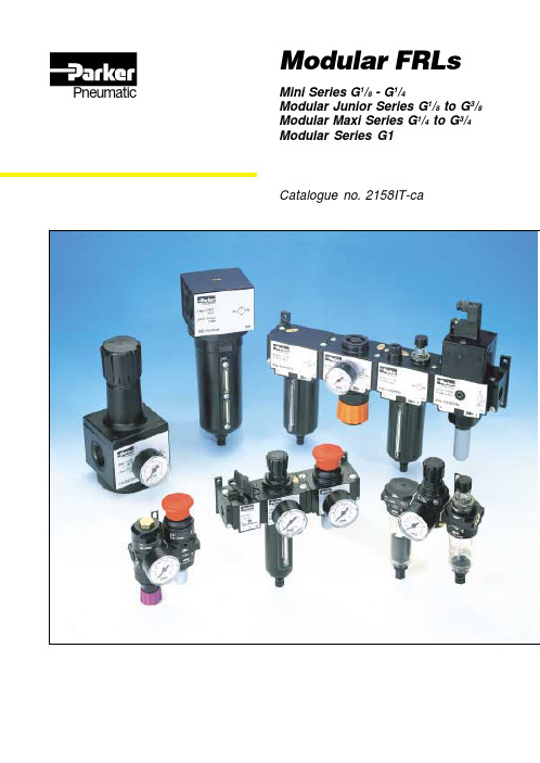
Modular FRLs Pneumatic Mini Series G1/8 - G1/4Modular Junior Series G1/8 to G3/8Modular Maxi Series G1/4 to G3/4Modular Series G1Catalogue no. 2158IT-caMini FRLs3Mini FRLsLa linea Mini FRL è destinata all'impiego in piccoli sistemi pneumatici o in centraline di comando dove lo spazio è limitato.Il sistema permette di collegare fra loro più unitàsenza dover ricorrere a elementi terminali; in tal modo esso consente un risparmio di spazio e crea interassi di montaggio costanti,assicurando allostesso tempo un aspetto esteticamente piacevole emoderno.II singoli filtri, regolatori, lubrificatori e filtri/regolatori sono tutti realizzati con un tecnopolimero di alta qualità e sono provvisti di connessioni integrate con filettature G 1/8 o G 1/4 realizzate con insertometallico che assicura una maggior robustezza meccanica quando le unità vengono usate singolarmente.Nel complesso i singoli prodotti sono estremamente leggeri; un'unità FRL completa pesa solamente 380grammi.Il sistema Mini FRLsManopole colorate8 bar Nera 4 bar Grigia 2 barBluMini FRLs4Principali combinazioniCombinazioni Filtro/Regolatore - LubrificatoreElementi da 5 micron, regolatore da 8 bar + manometro e staffe di montaggio a pareteConnessioniSerbatoio - Scarico Serb. trasparente Serb. trasparente Serb. trasparente Scarico manuale Scarico semiautom.Scarico a impulsi G 1/8P3A-CA11BGB P3A-CA11CGB P3A-CA118GB G 1/4P3A-CA12BGBP3A-CA12CGBP3A-CA128GBOpzioni:Nota:Per i materiali v. pag 16Per le dimensioni v. pag 17P3A-CBCombinazione Filtro/Reg. + binazione FR L Combinazione FRL + Manifold dopo Regolatore Combinazione F/R L + Manifold dopo Filtro/RegolatoreG 1/412Serbatoio trasparente Scarico manuale Serbatoio trasparente Scarico semiautomatico Serbatoio trasparente Scarico automaticoB C 8Senzamanom.Conmanom.NGA B KHG 1/811Combinazioni Mini FRLElementi da 5 micron, regolatore da 8 bar + manometro e staffe di montaggio a pareteConnessioniSerbatoio - Scarico Serb. trasparente Serb. trasparente Serb. trasparente Scarico manuale Scarico semiautom.Scarico autom.G 1/8P3A-CB11BGB P3A-CB11CGB P3A-CB118GB G 1/4P3A-CB12BGBP3A-CB12CGBP3A-CB128GBXXXX X56Principali combinazioniCombinazioni di valvole di scarico rapido e di avviamento progressivo con staffe di montaggio a pareteOpzioni:Nota:Per combinazioni personalizzateconsultare l'assistenza tecnicaP3A-CSolenoidi 15 mm Distanza PIN 8 mm Connessione pilota istantaneaG QG 1/412SNota:Per i materiali v. pag 16Per le dimensioni v. pag 17Per i solenoidi v. pag. 16Le valvole diverse da quelle a 24 V DC sono da ordinarsisenza solenoide, e il solenoide è da ordinarsi separatamente.Valvola di scarico rapido e valvola di avviamento progressivoConnessioni V alvola di scar. rapido azion. a solenoide + valvola di avviam. progres. con regolaz. man.24V DCSenza Solenoide G 1/4P3A-CS12GMB2CCP3A-CS12GMBØØØValvola di scarico rapido e valvola di avviamento progressivoConnessioni V alvola di scar. rapido azion. pilotata + valvola di avviam. progres. con regolaz. man.G 1/4P3A-CS12QMBPer i solenoidi v. pag. 16MB 24V DCSenza solenoide2CC 000XX XXX X7891011121314151617Montaggi assemblatiGruppo contemente un regolatore o filtro regolatore Gruppo senza regolatore o filtro regolatore Staffe di montaggio a parete montatealle estremita di un gruppoStaffe di montaggio a parete montatealle estremita di un gruppoStaffe di montaggio a parete montateall'interno di un gruppoStaffe di montaggio a parete montateall'interno di un gruppoPneumatic1819Pneumatic20Il sistemaIl sistema Modular permette di collegare fra loro piùunità senza dover ricorrere a elementi terminali; in tal modo esso consente un risparmio di spazio e crea interassi di montaggio costanti, assicurando allo stesso tempo un aspetto esteticamente piacevole e moderno.Il sistema è costituito da unità standard con corpo principale delle stesse dimensioni, adattatori intermedi e blocchi connettori separati con diverse filettature. In questo modo il progettista dispone di un sistema veramente modulare che può essere adattato ed ampliato per soddisfare le future esigenze dell'applicazione.Il sistema permette inoltre la rimozione delle unitàdalla linea d'aria senza toccare gli attacchi fissi,semplificando quindi notevolmente la manutenzione.Il sistema Modular è costituito da filtri, filtri acoalescenza, filtri ad assorbimento, regolatori, filtri/regolatori e lubrificatori per linee d'aria, a cui si aggiunge una vasta gamma di accessori fra cui valvole di avviamento progressivo, valvole di scarico rapido, Manifold e connettori con attacco posteriore.Montaggio a pareteKit staffe angolari regolatoreFiltro/regolatoreConnettore con attacco posterioreBlocco conn.Valvola a sferaManifoldAdattatore intermedioValvola di scaricoValvola di avviamentoprogressivoLubrificatoreRegolatoreFiltroManopole colorate16 bar Arancione 8 bar Nera 4 bar Grigia 2 barBluModular Junior FRLs2122232425262728Pneumatic29303132Pneumatic33Valvole per scarico rapido ad azionamento manualeSimboloTolgono la pressione a monte e scaricano pressione a valle.Manopola a scelta rossa o nera.Connessione G1/8, G1/4, G3/8.Scarico inferiore G1/4Versione bloccabile con lucchetto.Versioni a bloccaggio manuale o a 2 posizi oni.Opzioni:Le valvole per scarico rapido sono disponibili in 2versioni, la prima è una valvola del tipo a 2 posizioni con entrambe selezionabili.La seconda versione è bloccata dall'aria compressa,questa funzione richiede il posizionamento manuale della manopola fino a quando la pressione del circuito raggiunge un valore sufficiente al blocco dellamanopola. Nel caso in cui la pressione scende sotto il valore richiesto la valvola si riposiziona scaricando ilPressione max. di ingresso 10 bar max.Temperatura da -100C a +500CPortata G 1/814.5 dm 3/s G 1/417.5 dm 3/s Peso75gDati tecniciNota:Per i materiali v . pag. 34.Silenziatore incluso in ogni prodotto343536Montaggio assemblatiGruppo contenente un regolatore o filtro regolatoreGruppo senza regolatore o filtro regolatoreStaffe a parete montate alle estremità di un gruppo Staffe a parete montate alle estremità di un gruppoStaffe di montaggio su Filtro/RegolatorePrincipale combinazione con staffe di montaggioa parete3738Il sistemaIl sistema Modular permette di collegare fra loro più unità senza dover ricorrere a elementi terminali;in tal modo esso consente un risparmio di spazio e crea interassi di montaggio costanti, assicurandoallo stesso tempo un aspetto esteticamente piacevole e moderno.Il sistema è formato da unità standard con corpoprincipale delle stesse dimensioni, adattatori intermedi e blocchi connettori separati con diverse filettature. In questo modo il progettista dispone di un sistema veramente modulare che può essere adattato ed ampliato per soddisfare le future esigenze dell'applicazione.Il sistema permette inoltre la rimozione delle unitàdalla linea d'aria senza toccare gli attacchi fissi,semplificando quindi notevolmente la manutenzione.Il sistema Modular è costituito da filtri, filtri a coalescenza, filtri ad assorbimento, regolatori,filtri/regolatori e lubrificatori per linee d'aria, a cui si aggiunge una vasta gamma di accessori fra cui valvole di avviamento progressivo, valvole discarico rapido, Manifold e connettori con attacco posteriore.Manopole colorate16 bar Arancione 8 bar Nera 4 barGrigiaKit staffe angolari regolatoreFiltro/regolatoreConnettore con attacco posterioreBlocco conn.Valvola a sferaManifoldAdattatore intermedioValvola di avviamento progressivo/di scarico rapidoLubrificatoreRegolatoreFiltroModular Maxi FRLsPneumatic39Pneumatic40Pneumatic41Pneumatic4243Pneumatic44Pneumatic454647Pneumatic484950Montaggio assemblatiGruppo contenente un regolatore o filtro regolatoreGruppo senza regolatore o filtro regolatoreStaffe a parete montate alle estremità di un gruppo Staffe a parete montate alle estremità di un gruppoStaffe di montaggio su Filtro/RegolatorePrincipale combinazione con staffe di montaggioa parete。
恩泰克120模块组态说明
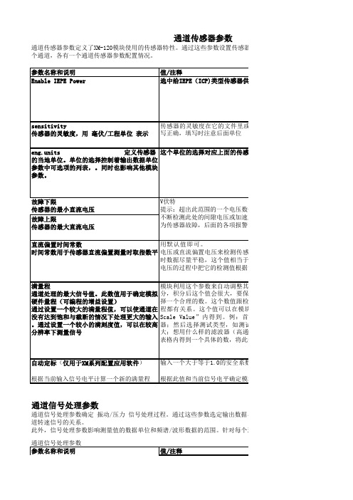
通道信号处理参数参数名称和说明通道信号处理参数确定 振动/压力 信号处理过程。
通过这些参数选定输出数据单位道转速信号的关系。
此外,信号处理参数影响测量值的数据单位和频谱/波形数据的范围。
针对每个通道,各有一个信号处理参数类型。
系统在通道传感器参数通道传感器参数定义了XM-120模块使用的传感器特性。
通过这些参数设置传感器的个通道,各有一个通道传感器参数配置情况。
AD 的量程。
其假设满量程时在最Guidelines for Setting t 通道信号处理参数值/注释,非常重要,一测量参数通频测量参数针对每一个通道各有一个通频测量参数类型。
通过这些参数配置测量方式和每个通频测量的滤波。
速度测量参数要:如果你没有正在使用转速计通道,应该将每转脉冲数设置为0。
使转速测量不起作用,模块提示转速计故障报警参数参数控制报警操作(警戒、危险级)、提供报警状态。
XM-120提供16种报警。
这些报警不一个通道,最多能够分配8个报警给任何一种测量。
使用这些参数配置测量和报警行为,使与报警结合起来。
120模块可定义16种报警,可以通过相同。
相同。
相同。
相同。
选中则有效清除则失效速度范围下限机械转速的下门限。
此值必须小于速度范围上限。
当转速范围开关失效时,此参数不起作用。
速度范围下限机械转速的上门限。
此值必须大于速度范围下限。
当转速范围开关失效时,此参数不起作用。
RPM (转/分钟)RPM提示:当转速范围开关有效时,必须存在转速信号(每转脉冲数设置高),并且必须提供转速信号。
转速范围开关继电器参数继电器参数控制自带继电器和继电器拓展模块继电器的操作。
通过使用这些参数来配置报应的继电器以及继电器的动作。
4-20mA输出参数4-20mA 输出参数定义这两个4-20mA 输出信号的特性。
对于每个输出,参数都是一样的。
参数名称和解释Xm configuration utility选中择有效清除则无效测量设置测量方式和4-20mA输出信号通过的通道监测数据参数参数名称和解释值/注释传感器故障可能状态值:在相关联的通道上是否存在传感器故障。
OVATION算法模块介绍
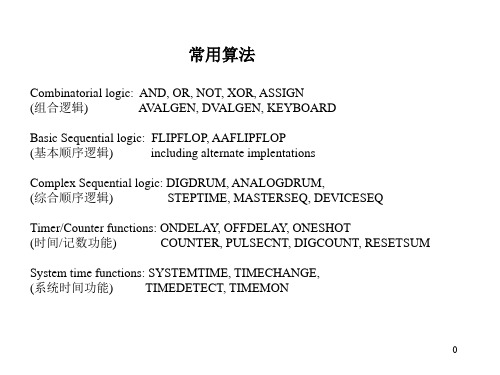
Timer/Counter functions 时间/记数功能
ONDELAY, OFFDELAY, ONESHOT, COUNTER, PULSECNT, DIGCOUNT, RESETSUM ONDELAY -- 前延时
16
OFFDELAY -- 后延时
17
ONESHOT -- 脉冲发生器
COMPARE, DBEQUALS
Filtering: RUNAVERAGE, SMOOTH, LEADLAG, TRANSPORT,
(滤波)
PREDICTOR
Transmitter processing: 2XSELECT, MEDIANSEL, GASFLOW,
(转送处理)
LEVELCOMP, STEAMTABLE, STEAMFLOW,
真值表:
? ? --- SET 优先, 则为“1”
RESET 优先, 则为“0”
3
AAFLIPFLOP -- 带复位的交替动作触发器
我 来 探 个 头 靠!怎 么搞的 ! “ 日”后 再说 直 到舒服 为止 呆 到自然 萌≈ 鬼 域失魂 地 ¢ ご 弑 血 ★冥君 转身 、遇见 鬼 停尸 房毫无 温度 姐 的大姨 妈都比 你红~ 洫 ╬══ 太 浓 把心 活活掐 死 诱惑 〃 Is 隔 世的知 己ㄟ ╘\╱ ‘ㄡ 鸟\ 艹 迩妈 好吗 ' 死八开 切、 浴 巾 里 的 风 景 舌尖 弥漫诱 惑つ 唇 角的酒 香。 迷 魂 Dreams▼ {.难 ! ?产 我 们、
24
HIGHMON -- 高值监视
System time functions: SYSTEMTIME, TIMECHANGE,
(系统时间功能)
TIMEDETECT, TIMEMON
CM-OP离线编程模块说明书
CM-OP离线编程模块说明书深圳市顾美科技有限公司V23.31版目录引言 (3)一、硬件说明 (4)1.1模块外观 (4)1.2指示灯状态及功能 (4)1.3产品优势 (5)1.4产品参数 (6)二、工作模式 (7)2.1模块与电脑通信 (7)2.2模块与PLC通讯 (11)2.3其它说明 (12)引言CM-OP离线编程模块作为有线数据传输模块,使用RS485及RS232通讯方式,使模块与PLC通讯直接进行程序上传下载工作。
特别是针对产线上的自动化设备,使程序下载工作变得轻而易举。
使工程师远离产线噪音,改善工作环境的同时又大大提高了工作效率。
功能齐全的同时操作简单易学,产线工人也可轻松掌握使用方法。
一、硬件说明1.1模块外观1.2指示灯状态及功能指示灯名称指示功能状态WORK 模块与PLC 通讯指示未通讯时常亮;通讯成功时约每秒闪烁1次;上传或下载数据时快闪;TXD 发送数据指示灯U 状态时,此灯闪烁D 状态时,此灯快闪RXD 接收数据指示灯U 状态时,此灯快闪D 状态时,此灯闪烁PWR 电源指示上电此灯常亮CHG充电指示USB 充电时闪烁1.3产品优势1、减少设备的停机时间,当对下一个任务进行编程时,之前的设备程序可以仍在生产线上工作;2、对于生产线上的自动化设备,使用模块对PLC下载程序,可使编程者远离繁重的搬运工作,改善了编程环境;3、离线编程使用范围广泛,可以对FX2N系列、FX3G系列等PLC进行程序编程;4、用户使用方便,适应性强,能方便地实现优化编程;5、便于更改PLC程序,提高工作效率;6、无须参数设置,即插即用;7、内置可充电电池,单次充电可不间断使用5小时以上;1.4产品参数产品类型CM-OP 离线编程模块产品图片正面侧面安装方式35MM 标准导轨安装、手持设备连接方式MICRO USB &RS485/RS232通讯协议三菱编程口协议电源电压内置2000mAH 可充电锂电池充电电压5V 最大输入电流50mA 静态功耗<0.5W 净重50g 外型尺寸90mm*60mm*32mm 工作环境温度-20℃~85℃编程软件兼容三菱PLC 编程软件GX8.52/GX8.86和WORKS 2相关手册下载:二、工作模式2.1模块与电脑通信1、模块与电脑通过USB进行连接,连接方法如下图所示:此时电脑的设备管理器中会出现一个对应的串口(电脑需要安装USB转串口驱动,驱动可至顾美官网:配套软件下载---《USB转485驱动》下载),如COM5:2、给模块上电(USB接通或者打开电源开关)。
Modicon Quantum 自动化平台介绍

根据容量分类: 根据容量分类:
3A 8A 11A
红色:常用类型 红色:
Unity V2.0
7
Modicon Quantum 设计
模板特点 模板特点
任何模块可插在任何位置 与槽位无关 软件编址 模块电子 ID (CPU) ) 保证用户配置与实际模块一致 可带电更换任何模板 即插即用 不会损坏 所有I/O模板的配置及编址通过软件实现,无跳线或 所有 模板的配置及编址通过软件实现,无跳线或DIP开关 模板的配置及编址通过软件实现 开关
Unity V2.0
15
Modicon Quantum CPU 性能一览
31110
CPU主频 主频 本地站 I/O字 字 远程站I/O字 远程站 字 远程站数量 通讯、网络模块数量 通讯、 内置以太网口 内置 USB 口 集成内存 状态寄存器 可使用内存扩展卡 应用程序最大存储量 数据文件最大存储量
1024KB 128 KB
3072KB 128 KB
1024KB 128 KB
7 MB 8 MB
7 MB 8 MB
7 MB 8 MB
7 MB 8 MB
Unity V2.0
16
多任务、 多任务、高性能
满足不同的应用需求
多任务系统
主任务 快速任务 事件任务 定时中断 I/O中断 辅助任务
高性能
布尔指令 数字指令 浮点指令
出错、保险断、I/O点指示 模块种类用颜色区分-减少错误机会 模块上有完整部件号和模块描述
Unity V2.0
10
Modicon Quantum 设计
可选的涂层保护模板 可选的涂层保护模板
通过敷形涂覆延长控制系统的使用时间 防止化学雾气、有机溶剂、粉尘、潮湿、霉变等对机器的侵蚀 典型应用: 金属还原(钢,铝),污水处理,沿海的场所,石料粉碎 标准及认证 涂层: 聚氨脂, Humiseal 1A33 美国军标: MIL-I-46058C 抗真菌: ASTM G-21 抗粉尘,化学雾气,抗污染: EIA-364-TP91, EIA 364-65 and ISA-S71.04 (GX severe mixed flow gases) IEC 盐雾测试: IEC 68-2-11 @ 5.7%
- 1、下载文档前请自行甄别文档内容的完整性,平台不提供额外的编辑、内容补充、找答案等附加服务。
- 2、"仅部分预览"的文档,不可在线预览部分如存在完整性等问题,可反馈申请退款(可完整预览的文档不适用该条件!)。
- 3、如文档侵犯您的权益,请联系客服反馈,我们会尽快为您处理(人工客服工作时间:9:00-18:30)。
基于产品的变型,管理和验证工艺变型。
- Customizable Tabs
用户可以根据需要自己在用户界面中加客户化的表。
- Time Sheet Integration.
通过“时间”模块(电子数据表集成),规划人员可以很容易把MTM时间值分配给各个作业。该时间模块提供以下数据卡片模式:MTM数据卡片,支持UAS,MEK,等等。
Change Management 提供了预配置的、最佳实践解决方案,以在整个企业的基础上发起、管理、评审/批准和执行产品变更。 Change Management 支持正式和次正式的过程,利用多种变更文档(比如,变更单和变更通知),根据行业标准的闭环变更模型的需要、可重复地和系统地管理产品变更。利用这些最佳实践,可以说明设计意图中的变更,追溯整个产品生命周期中所有相关的依赖关系和决策。
8
TN70015
Process Simulate Spot
能使用户创建点焊焊接工艺,从早期的规划阶段到详细工程阶段。分配焊点到相应的工位,满足几何和循环时间的约束,选择最合适的焊枪。
9
TN70010
Assembler
用来设计、分析、验证产品的装配和分解过程,软件提供的具有层次性的装配树,可以方便的创建和仿真装配路径和操作顺序,对碰撞冲突和2D和3D切面和测量分析
2
TN55010
Alternative Planning
用户可以管理不同的规划方案,可以创建、比较和更新不同的比较方案。
3
TN55025
Automated Process Generator
“Automated Process Generator”是一种用于根据给定的产品数据(BOM)建造装配流程的工具。工艺工程师可以规划装配流程并且在一个直观的三维环境中自动生成工艺流程树。
-创建工区;
-关联资源到工区、工艺、工序;
-关联产品到工艺和工序;
-生成报表;
创建和编辑Pert图;
-EBOM与装配工艺装配件一致性检查;
-装配工艺修改;
-装配树;
26
TCM24804
Teamcenter Manufacturing Documentation
该模块提供包括基于Visio的作业指导文档。可生成内容丰富并与Teamcenter集成的文档
13
TN70025
Commissioning
Commissioning能够对一个工作单元进行虚拟的试运转,使用真实的PLC程序来确认包含机器人和装置的工作环境。
14
TN70037
Process Simulate Continuous Manufacturing
连续制造过程规划仿真,本功能模块提供了一个从粗规划阶段到详细规划阶段和离线编程的整个连续制造过程的开发工具;
包括用来创建或导入焊缝的工具,连续焊接路径的创建、机器人可达性研究和测试等。
15
TN70070
Automatic Path Planner
TheVendor:KINEO(第三方)
自动工艺路径规划,在连续的操作动作和机器人焊接操作路径规划时,系统能在的复杂装配和机器人线中避免碰撞而自动生成路径,节省大量的规划设计时间。
Change Management还包括工具:能以图形方式分析物理Items的变更历史记录及其关系,以便将需求变成文档。
24
TCM55000
Teamcenter Manufacturing Access
该模块使得用户可以查看制造数据结构
用户可以:
创建、查看及储存报表
创建、编辑附件
浏览工艺、工厂结构
查看工艺、资源关联关系
22
TC10102
Teamcenter Consumer
利用consumer许可证,可以对产品和过程信息进行查看、批准、拒绝或者批注。任何用户许可证都可以执行用Teamcenter 开放式工具编写的定制扩展。
23
TC10231
Change Management Author
利用Change Management,可以创建变更文档(包括所有支持信息),以定义supercedures,管理扩展企业中的变更过程,并且对变更进行审计。
19
TN55040
User Task Manager Float
Task Supervisor enables the users to determine a set of process validation tasks, attach tasks to eMS objects, and indicate these tasks status. Managers & supervisors are then capable to generate comprehensive reports that indicate what the status of a planning project is, in a glance. The type of takes and their status is fully customized to reflect different customer needs
4
TN55065
Robcad Integration
与Robcad集成。
5
TN55080
Layout Integration
该模块可以与Microstation和AutoCAD集成,用于在一个二维环境中进行资源规划和定义;该模块与Process Designer模型有关联性;要求客户有Microstation和AutoCAD软件和许可。
6
TN55015
Line Balancing
用来在制造过程中识别关键路径,并提供方便的界面用来平衡生产线上的操作,达到提高产量的目的
7
TN70005
Process Simulate
Process Simulate能够规划和设计复杂的装配设备、生产线和工位。产品支持层次结构,从工厂布局、仿真到生产线布局、到单个工位的详细设计和优化。
10
TN70075
Standard Interface Package
与DXF, IDI IN, IGES和STL IN的接口模块。
11
VS22195
Pro/E to JTTranslator
Pro/E toJT转换器
12
TN70020
Robotics
能使用户创建非常复杂的机器人制造区域。机器人仿真工具提供了设计所有机器人无干涉的路径的能力,并能通过在一个区域中的多台机器人同步来优化循环时间。
- SDK Runtime environment
SDK(软件开发工具包)是一套软件(ActiveX)组件,可以与API应用程序合并;这些组件是标准的工具,带有标准的用户接口和标准特征。
- Generic Process Configurator
通过“Generic Process Configurator”,在新产品概念阶段,用户可以设计、规划和捕捉通用的制造流程;设计好的通用制造过程可以在日后自动应用于不同的产品配置,或者重复用于类似的产品;可以比较并评估通用和变异流程的备选方案。
Human Advanced是一个附加的人体工具。Human Advanced提供了更加详细的人体模型带有高级的人体测量功能。利用高级姿态工具能够快速的评估装配和维修研究要求的复杂的人体姿态,支持一般的人因工程分析报告。还有附加的不同国家的人体模型
18
TN55045
PLP Manager
PLP Manager is a Body In White tool for distributing Datums (PLP). The application enables users to design the datum points for each station, and, in addition, to perform a smart search for the purpose of reusing datum from station to station
27
TCM55010
Teamcenter Manufacturing Resource Manager
该模块使得用户能够定义资源零件及其装配件。这些资源可以分类并存入分类库
功能:
创建资源
创建图形
检索
生成报表
用途检查
查看、编辑与资源相关联的文档
16
TN70030
Process Simulate Human
Human能使用户设计、分析和优化详细的人工操作。软件提供了不同大小的虚拟人体模型用于人工操作模拟及人因工程和操作时间分析。Human提供了方便的工具检查人工操作、交互式的改进人工工位和评估不同的设计变量
17
TN70031
Process Simulate Human Advanced
21
TC10101
Teamcenter Author
Author许可证允许命名用户在Teamcenter里面创建数据。
有两种Teamcenter 提供了广泛的数据存储、检入/检出、版本管理、属性同步和搜索等功能,该产品不仅提供了管理产品结构的能力,而且还提供了一套过程和工作流的自动化工具。
利用该author许可证,用户可以创建和修改产品和过程信息。
20
TN55055
Pack and go
Pack and go enables the user to pack a scope of data, export it and attche the relevant 3D file to the zipped output. The user is able to filter out attributed which she doesnt want to disclose. A user who gets this packed info is than able to import and review / edit the data