maintenance-manual
GEA 卧床使用和维护手册说明书

Rev.05 09/2020 USE AND MAINTENANCE MANUAL GEA COUCH SET-CLOSE SERIESGEA COUCH MODELSDescription CodeGEA 116010Table of contentsINTRODUCTION p. 3 SAFETY – WARNINGS – WARRANTY p. 4 PACKAGING AND UNPACKING p. 5 PRODUCT LABEL AND SYMBOLS p. 6 TECHNICAL SPECIFICATIONS – ASSEMBLY p. 7 WARNINGS – MAINTENANCE p. 8 CLEANING p. 9 SPARE PARTS, OPTIONAL ACCESSORIES p. 10 INSPECTION DATA SHEET p. 11The purpose of this manual is to provide users and operators with the necessary information to use the couch properly, autonomously, and safely.This manual contains information on the technical features, operation, maintenance, spare parts and security of the couch.This manual must always be carried with the equipment and stored with care so that the readability is not compromised.In case of transfer of use to a third party, this manual must be transferred as well, along with the other documents, as provided by Council Directive 93/42/EEC.Intended useThe GEA couch is a metal frame, fixed height couch used by rehabilitation and physiotherapy professionals.Manufacturer’s detailsFISIOTECH SRLOperating headquarters: Via Toniolo, 44/E-F31028 VAZZOLA (TV) - ItalyTel. +39 0438 470342Fax +39 0438 478762******************Area of useThe medical devices described in this manual comply with the Directive 93/42/EEC as modified by Annex VII to Directive 2007/47/EC. Area of use: outpatient care carried out under medical supervision in hospital or in another medical centre where the medical electrical equipment are used for the treatment, diagnosis and monitoring of sick patients, people who have sustained injuries and people with disabilities.StoringIn case of storing, the following environmental conditions must be ensured: relative humidity 10% ÷ 90 % - temperature -10°C ÷ +50°C – Clean place.WARNING! Do not use the couch:∙Beyond its declared maximum safe working load.∙On unstable floors or near inclined floors, steps, etc.∙If it has been tampered with or modified.∙In a potentially explosive atmosphere where a fire hazard or corrosion may occur, or exposed to the weather.∙With an inappropriate configuration or if you suspect it may harm the patient.WARNING!∙Do not touch the moving areas of components and/or controls, which are specifically labelled.∙Expanded rubber and plastic components of the device may catch fire if exposed to open flames.∙Therapy lamps may damage the upholstery.∙Corrosive and/or abrasive cleaning agents may damage the upholstery.∙We recommend using a couch paper sheet between the patient and the antibacterial and fungicide leatherette and to replace it at the end of the treatment/examination.The GEA couch warranty covers only the manufacturing defects for 24 months starting from the date of delivery. The warranty does not cover: consumables and items of normal wear – such as upholstery –, breakdowns caused by any impact and/or fall, wrong or improper use, use by non qualified personnel. The warranty is void if the device has been tempered with. Warranty repairs are carried out at our operational headquarters and prior authorization. The products to be repaired under warranty must be shipped to the manufacturer freight prepaid and with the original packaging. A copy of the invoice and of the transport document has to be sent along with a written request in order for the products to be repaired.The packaging consists of a cardboard box, with a lid and a bottom. The box is closed with iron staples and placed on a pallet especially designed for this kind of box. The box is secured to the pallet with plastic straps.After placing the pallet containing the couch on a suitable surface cut the plastic straps securing the pallet to the couch and closing the box.∙Fixed height 78 cm.∙Dimensions 190 X 65 X 50 cm.∙Headrest angle +60° with “rastofix”.∙Breathing hole and bung.∙Maximum working load kg 150, evenly distributed.∙Struttura del lettino in acciaio verniciato.∙ Powder-coated steel frame.∙ 4 cm-thick polyurethane foam fireproof padding. Density: 30 kg/m³.∙Fireproof leatherette upholstery.∙Push the legs of the couch all the way through inside the frame of the couch.∙Tighten the screws with a wrench to block the legs.WARNINGThe headrest can be adjusted with a “rastofix” rack. Raise the headrest until you reach the desired inclination. To lower the headrest, lift the headrest until you reach the max inclination, then lower it.Maintenance must be carried out by a specialist, an electrician or someone who is familiar with the content of this manual.Check the safety conditions of the device after any incident such as falls, violent impacts, spilling of liquids, etc. and any time you deem it necessary.The use of disinfectants is advised in order to disinfect hands and other parts of the body that came into contact with the patient or other surfaces.Cleaning the upholstery:Clean with a damp soft cloth with a neutral detergent solution, rinse with clean water.WARNING!∙Do not use solvents, bleaches, synthetic detergents or polishing sprays.∙Avoid direct sunlight on the upholstery in order to avoid early ageing.∙Excessive rubbing may cause the early ageing of the device. Thoroughly verify that this operation is carried out correctly.∙Light colours should not come into contact with fabrics and clothes which have been treated with unbound dye or not properly dyed in order to avoid colour spots and stains which may not be removed.SanitationSpray the surface with a 0.5% peroxide-based solution and rinse thoroughly. FREQUENCY: Daily up to 6/8 per dayWARNING! Using detergents with additives and/or alcohol tends to increase the wear and tear process and the ageing of the surface.Cleaning of the structure:Gently dust with a dry or at most a lightly damp non-abrasive cloth.WARNING!1. Aggressive products may damage the frame and the upholstery.2. Check whether all the components are completely dry before using the device aftercleaning.11 of 11。
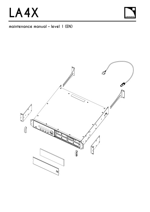
L-Acoustics LA4X 维护手册说明书
LA4X Arraymaintenance manual – level 1 (EN)ContentsDocument reference: LA4X maintenance manual - level 1 (EN) version 2.0Distribution date: March 20, 2017© L-Acoustics. All rights reserved.No part of this publication may be reproduced or transmitted in any form or by any means without the express written consent of the publisher.ContentsContentsSafety instructions 4 Symbols 4 Revision history 5 Introduction 6 1Equipment and tools 7 2Quality Control 8 3Troubleshooting and diagnosis 10 Diagnosis table (10)Exploded view (16)Working time (16)4Disassembly and Reassembly procedures 17 D/R 001 – REAR BRACKETS (17)D/R 002 – SIDE BRACKETS (18)D/R 003 – GRILL and FOAM FILTER (19)D/R 004 – Power plug (20)D/R 004 bis – FRONT HANDLE (21)Glossary 22 Appendix: KR list 23Safety instructionsSafety instructions1.Strictly follow the sequence of successive steps in all procedures.2.This manual contains the maintenance operations authorized for the end users.Performing another operation exposes to hazardous situations.3.Never incorporate equipment or accessories not approved by L-Acoustics®.4.Do not expose the apparatus to extreme conditions.Do not expose the apparatus to dusty environments, moisture or excessive heat when storing orperforming maintenance procedures.5.Do not store the product on an unstable cart, stand, tripod, bracket, or table.6.Never use a faulty apparatus.An apparatus showing any sign of issue must immediately be put aside and withdrawn from use.7.Contact L-Acoustics for advanced maintenance.Any unauthorized maintenance operation will void the warranty.Before sending a product to L-Acoustics for maintenance, save all user presets to files usingLA Network Manager.SymbolsThe following symbols are used in this document:This symbol indicates a potential risk of harm to an individual or damage to the product.It can also notify the user about instructions that must be strictly followed to ensure safe installation or operation of the product.This symbol indicates a potential risk of electrical injury.It can also notify the user about instructions that must be strictly followed to ensure safe installation or operation of the product.This symbol notifies the user about instructions that must be strictly followed to ensure proper installation or operation of the product.This symbol indicates the equipment, tools, and spare parts required to perform a procedure.This symbol notifies the user about complementary information or optional instructions.Revision historyRevision historyDocument identification Distribution date ModificationsLA4X_MM1_EN_1.0 June 10, 2014 Initial versionLA4X MM1 EN version 2.0 March 20, 2017 - Added D/R 004 bis – FRONT HANDLE- Updated Exploded view- Updated Appendix: KR listIntroductionIntroductionThis manual is intended for end users and gathers the level 1 procedures.This manual contains the maintenance operations authorized for the end users.Performing another operation exposes to hazardous situations.Diagnosis tableThis section contains the diagnosis tables and procedures to identify the issues and how to address them.Exploded viewThis illustration gives an overview of the order in which the elements must be disassembled and reassembled. Each assembly refers to the corresponding module, D/R procedure and inspection procedure (if any).Disassembly and Reassembly proceduresThis section contains the maintenance procedures for each assembly identified in the exploded view.Quality ControlThese checks allow to detect an issue. The quality control must be performed regularly.It is mandatory to perform preventive maintenance actions on a regular basis.Insufficient upkeep of the product can void the warranty.Equipment and tools1Equipment and toolsThe following table is the complete list of equipment and tools required to perform all level 1 maintenance procedures on the LA4X amplified controller.* Refer to the documentation of the electric screwdriver manufacturer to obtain the setting corresponding to a given torque value. This setting can vary depending on the age of the tool. Verify it on a regular basis.Quality Control2Quality ControlThis procedure must be performed for periodic maintenance and to detect possible issues on a controller. ToolsNameaudio source with a known musical programLA NWMCAT5e U/FTP cablefull range loudspeakersubwooferear protectionsProcedureInspect the external structure of the controller for any lost or damaged part.To verify if the controller is clean, follow these steps:a.Disassemble the GRILL and the FOAM FILTER, see procedure D/R 003.b.Verify if the FOAM FILTER is clean.c.Look inside the controller through the front grill (do not touch any part) and verify if the inside is clean.d.Reassemble the GRILL and the FOAM FILTER, see procedure D/R 003.Plug the controller to mains and power it on.Verify if the LCD screen and all LED lit during the start-up sequence.To verify if the network functionalities of the controller work, follow these steps:a.Connect the controller to an Ethernet port of the computer hosting LA NWM.Use the CAT5e U/FTP cable.unch LA NWM.c.Verify if the controller can be put in online mode (refer to the LA NWM video tutorial).Verify if the latest version of firmware is installed (see the LA4X user manual or the LA NWM videotutorial).If not, update firmware from LA NWM.Select a known preset and verify if the indications displayed on screen are in accordance with it.To verify sound presence and quality on each output channel follow these steps:a.Plug the audio source to an input connector of the controller (IN A, IN B, IN C or IN D).b.Plug the full range loudspeaker to output connector OUT1.c.Select a corresponding preset.d.Select the routing from the audio source to OUT1.e.Play the musical program.f.Set the OUT1 gain to -40 dB.g.Unmute OUT1.h.Set the OUT1 gain to obtain a medium sound level.i.Verify if the sound is clear and undistorted.j.Mute OUT1.k.Repeat these steps for OUT2, OUT3 and OUT4.Quality Control There is a risk of ear damage due to high sound level.Use ear protections.To verify the power capability of each output channel follow these steps:a.Plug the audio source to an input connector of the controller (IN A, IN B, IN C or IN D).b.Plug the subwoofer to output connector OUT1.c.Select a corresponding preset.d.Select the routing from the audio source to OUT1.e.Play the musical program.f.Set the OUT1 gain to -40 dB.g.Unmute OUT1.h.Set the OUT1 gain to obtain a high sound level.i.Verify if the sound remains clear and undistorted up to the limit level.j.Mute OUT1.k.Repeat these steps for OUT2, OUT3 and OUT4.Troubleshooting and diagnosis3Troubleshooting and diagnosisDiagnosis tableFor any issue, follow the check sequence in the possible causes column.At each step, apply the inspection procedure (if exists) and consider the resulting diagnosis.Before applying a procedure, consider the EXPLODED VIEW to get acquainted with the disassembly/reassembly procedures to perform before and after.Troubleshooting and diagnosisPOWER CORD notconnected to mainsmains failure or wrongvoltagePOWER CORDdamagedother causecontroller connected to anon-compatible networkcondensing humidity intothe LCD screenother causeTroubleshooting and diagnosisTroubleshooting and diagnosisroom temperature too highFOAM FILTER cloggedcontroller not gettingenough cool airchannel x resourcessolicited to their limitsloudspeaker impedance toolowother causesporadic errorother causesfirmware update failureother causeTroubleshooting and diagnosisFAN blades blockedanythe mains failureoutputs mutedwrong input modewrong preset selectiongain value too low on the controlleraudio source not plugged or plugged into the wrong input connectoraudio source cable incorrectly plugged audio source cable damagedwrong settings on the audio sourcenon-audio bit stream audio source failureloudspeaker not plugged or plugged into the wrong output connector loudspeaker cable incorrectly plugged loudspeaker cable damagedloudspeaker damaged other causesTroubleshooting and diagnosisAES/EBU audio sourceconnected to anANALOG inputgain value too high onthe controlleroutput gain value toohigh on the audio sourceswitch to the analogfallback mode withwrong AES/EBU inputgain valuewrong preset selectionaudio source cableincorrectly pluggedaudio source cabledamagedwrong settings on theaudio sourceaudio source failureloudspeaker pluggedinto the wrong outputconnectorloudspeaker cableincorrectly pluggedloudspeaker cabledamagedloudspeaker damagedother causesTroubleshooting and diagnosisExploded viewThe following exploded view represents the external MODULES of the LA4X. Each MODULE is indicated by a circled number. The orange lines represent the disassembly/reassembly (D/R) order. Refer to the table below for more information.Working timeDisassembly and Reassembly procedures4 Disassembly and Reassembly proceduresD/R 001 – REAR BRACKETS Spare parts KR LABRACKETDisassembly procedureThis procedure describes how to replace the REAR BRACKETS of an LA4X amplified controller. Remove the two REAR BRACKETS pulling on them, see Figure 1.Figure 1: Removing the REAR BRACKETSReassembly procedureThis procedure describes how to mount the REAR BRACKETS kit to an LA4X amplified controller. Insert the two REAR BRACKETS pushing on them until they are locked, see Figure 2.Figure 2: Mounting the REAR BRACKETSDisassembly and Reassembly proceduresD/R 002 – SIDE BRACKETSToolsNameelectric screwdriverTorxSpare partsKR LA4XEQAVDisassembly procedureThis procedure describes how to remove the SIDE BRACKETS from an LA4X amplified controller.Undo the four Torx® screws from the locations indicated in Figure 3.Use the electric screwdriver with the Torx® T10 bit.Figure 3: Removing a SIDE BRACKET Remove the SIDE BRACKET from the controller.Repeat these steps for the other SIDE BRACKET.Reassembly procedureThis procedure describes how to mount a SIDE BRACKETS kit to an LA4X amplified controller.Position a SIDE BRACKET on the controller.Drive four Torx® screws to the locations indicated in Figure 4.Use the electric screwdriver with the Torx® T10 bit. Torque to 1 N.m.Figure 4: Mounting a SIDE BRACKET Repeat these steps with a second SIDE BRACKET on the other side of the controller.Disassembly and Reassembly proceduresD/R 003 – GRILL and FOAM FILTER ToolsName3.5 mm flat screwdriverSpare parts KR LA4XGRI KR LA4XMOU Disassembly procedureThere is a risk of electrical injury and a risk of trapping finger/handBefore any maintenance operation, disconnect the controller from mains and wait for 1 minute so the capacitors discharge completely.This procedure describes how to remove the GRILL and FOAM FILTER from an LA4X amplified controller. Insert the head of the screwdriver in the hole indicated in Figure 5.Figure 5: Removing the GRILLPush the internal latch with the screwdriver and pull out the right side of the GRILL. Push the internal latch with the screwdriver again until the latch comes out of the hole. Remove the GRILL and the FOAM FILTER from the controller.If the FOAM FILTER is intended to be cleaned, use mild dishwashing detergent or soap and then dry it.Reassembly procedureThis procedure describes how to mount a GRILL kit and a FOAM FILTER kit to an LA4X amplified controller. Place a FOAM FILTER into the GRILL.Insert the left side of the GRILL into the controller. Insert the internal latch into the controller. Use the screwdriver.Push on the right side of the GRILL until hearing a click sound.Disassembly and Reassembly proceduresD/R 004 – Power plugToolsNamewire stripping pliersStanley knifescrewdriver adapted to the new powerplugSpare partsSafetyThere is a risk of electrical injury when the high-voltage capacitors are charged.Before the maintenance operation, disconnect the POWER CORD from the mains and from the controller.Replacement procedureThis procedure describes how to replace the power plug on a POWER CORD.Unplug the POWER CORD from the mains.Unplug the POWER CORD from the controller.Cut the POWER CORD near the power plug.Use the Stanley knife.Strip the three wires of the POWER CORD on a length compatible with the new plug.Use the Stanley knife and the wire stripping pliers.Fix the three wires on the new plug according to the color code of Table 1.Use the screwdriver.Table 1: Wire color codeDisassembly and Reassembly proceduresD/R 004 bis – FRONT HANDLEToolsNameelectric screwdriverTorxSpare partsG03255Disassembly procedureThis procedure describes how to remove the FRONT HANDLE from an LA4X amplified controller.1.Undo the two Torx® screws from the locations indicated in Figure 6.Use the electric screwdriver with the Torx® T15 bit.2.Remove the FRONT HANDLE from the controller.3.Repeat these steps for the other FRONT HANDLE.Reassembly procedureThis procedure describes how to mount a FRONT HANDLE to an LA4X amplified controller.FRONT HANDLES can only be mounted on compatible FRONT STRUCTURE.To upgrade a controller with a non-compatible FRONT STRUCTURE, contact your L-Acoustics representative.Self-drilling screwsFor safety reasons, always reassemble new FRONT HANDLES.1.Position a FRONT HANDLE on the controller.2.Drive two Torx® screws to the locations indicated in Figure 6.Use the electric screwdriver with the Torx® T15 bit. Torque to 1 N.m3.Repeat these steps for the other FRONT HANDLE.Figure 6: Mounting a FRONT HANDLEGlossaryGlossaryCE EuropeCN ChinaD/R disassembly/reassemblyKR Replacement KitLA NWM La Network Manager remote control softwareMODULE part of an amplified controller, written in uppercase characters N.m newton meter, international torque unit, 1 N.m = 9 in.lb fUS United StatesAppendix: KR list Appendix: KR listL-Acoustics, an L-Group Company13 rue Levacher Cintrat – 91460 Marcoussis – France+33 1 69 63 69 63 –********************L-Acoustics GmbH Steiermärker Str. 3-5 70469 StuttgartGermany+49 7 11 89660 323L-Acoustics Ltd.PO. Box Adler Shine - Aston HouseCornwall Avenue - London N3 1LFUnited Kingdom+44 7224 11 234L-Acoustics Inc.2645 Townsgate Road, Suite 600Westlake Village, CA 91361USA+1 805 604 0577。
大宇(DB58 T TI TIS)柴油发动机操作与维护手册说明书

OPERATION andMAINTENANCE MANUALDIESEL ENGINEDB58 DB58S DB58T DB58TI DB58TIS65.99897-8079e pc at al o g s .c omFOREWORDThis maintenance manual is designed to serve as a reference for DAEWOO Heavy Industries Ltd's (here after DAEWOO’s) customers and distributors who wish to gain basic product knowledge on DAEWOO's DB58, DB58S, DB58T, DB58TI and DB58TIS Diesel engine.This economical and high-performance diesel engine (6 cylinders, 4 strokes, in-line, direct injection type) has been so designed and manufactured to be used for the overland transport or industrial purpose. That meets all the requirements such as low noise, fuel economy, high engine speed, and durability.To maintain the engine in optimum condition and retain maximum performance for a long time, CORRECT OPERATION and PROPER MAINTENANCE are essential.In this manual, the following symbols are used to indicate the type of service operations to be performed.RemovalAdjustmentInstallation CleaningDisassemblyPay close attention-Important ReassemblyTighten to specified torque Align the marksUse special tools of manufacturer's Directional IndicationLubricate with oilInspection Lubricate with grease MeasurementDuring engine maintenance, please observe following instructions to prevent environmental damage;z Take old oil to an old oil disposal point only.z Ensure without fail that oil will not get into the sea or rivers and canals or theground.z Treat undiluted anti-corrosion agents, antifreeze agents, filter element andcartridges as special waste.z The regulations of the relevant local authorities are to be observed for thedisposal of spent coolants and special waste.If you have any question or recommendation in connection with this manual, please do not hesitate to contact our head office, dealers or authorized service shops near by your location for any services.For the last, the content of this maintenance instruction may be changed without notice for some quality improvement. Thank you.DAEWOO Heavy Industries & Machinery LTD.Aug. 2003e pc at al o g s .c omCONTENTS1. GENERAL INFORMATION1.1 Engine specifications 1 1.2. Engine power 2 1.3. Performance curve 3 1.4. Engine assembly 7 1.5. Safety regulations 132. TECHNICAL INFORMATION2.1. Engine model and serial number 17 2.2. Engine type 18 2.3. Engine timing 18 2.4. Valves 18 2.5. Lubrication system 18 2.6. Air cleaner 21 2.7. Fuel system 22 2.8. Cooling system 25 2.9. V-belt tension check and adjust 28 2.10. Valve clearance and adjustment 29 2.11. Cylinder compression pressure 30 2.12. Injection nozzle 31 2.13. Battery 31 2.14. Starting motor 31 2.15. Diagnosis and remedy 323. MAINTENANCE3.1. Engine Disassembly 42 3.2. Engine Inspection 63 3.3. Reassembly 88 3.4. Electrical Equipments 1074. Commissioning and Operation4.1. Preparation 114 4.2. Starting and operation 115 4.3. Inspections after starting 117 4.4. Operation in winter time 117 4.5. Maintenance and care 119 4.6. Cooling system 121 4.7. Valve clearance and adjustment 122 4.8. Injection timing 124 4.9. Tightening the cylinder head bolts 127 4.10. Cylinder compression pressure 128 4.11. Injection nozzle 128e pc at al og s .c om4.12. Fuel injection pump 129 4.13. Feed pump strainer 129 4.14. Separator 129 4.15. Air bleeding 130 4.16. Belts 1305. Maintenance of Major Components5.1. Lubrication system 133 5.2. Cooling system 137 5.3. Fuel system 142 5.4. Turbocharger 172 5.5. Air Intake System 1806. Special Tool List183Appendix 184 WORLDWIDE NETWORKe pc at al og s .c om1. GENERAL INFORMATION 1.1. Engine specificationsBuy nowDaewoo Doosan DB58 DB58S DB58T DB58TI DB58TIS Diesel Engine Operation and Maintenance Manual PDFWith Instant Download。
400V开关柜操作及维护手册-(双语)

MNS型400V开关柜操作与维护手册Operation and Maintenance Manual of MNS 400V Switch Cabinet1.引言1 Introduction1.1操作与维护手册说明1.1 Operation and maintenance manual instructions⏹ 正确操作MNS型400V开关柜,要求搬运、安装、操作及维护都由具有相关资质的专业人员来进行;⏹ In order to ensure proper operation, only qualified professionals can handle,install, operate and maintain MNS 400V switch cabinet;⏹ 为了避免人员遭受电击的危险,要求在安装或者维护之前对系统断电;⏹ In order to avoid electric shock, the system shall be disconnected from powerbefore installation or maintenance;⏹ 本指导手册的目的在于让相关人员熟悉MNS型400V开关柜的安装、维护保养过程及可能遇到的危险。
相关人员必须具备以下条件:⏹ The Manual intends to help relevant personnel to understand installation andmaintenance process of MNS 400V switch cabinet and possible dangers.Relevant personnel must meet following conditions:➢ 具有操作带电设备的资质;➢ Qualified for operating live equipment;➢ 接受过相关安全知识的培训。
维修手册的种类Manual overview

ATA Membership
• The Air Transport Association Bylaws provide that applicants for membership should be common carriers in air transportation of passengers and/or cargo; operate a minimum of 20 million revenue ton-miles (RTMs) annually, and have done so for one year preceding the date of application; and have a valid operating certificate that the Federal Aviation Administration has issued pursuant to Section 44705 of Title 49 of the U.S. Code.
• • • •
• • • •
• •
ATA Spec 109 - No-Fault-Found Process ATA Spec 111 - Airworthiness Concern Coordination Process ATA Spec 113 - Maintenance Human Factors Program Guidelines ATA Spec 114 - Fall Protection Guidelines for Airline Personnel During the Servicing and Maintenance of Aircraft ATA Spec 117 - Wiring Maintenance Practices/Guidelines ATA Spec 2000 - E-Business Specification for Materiels Management ATA Spec 300 - Specification for Packaging of Airline Supplies FOD - Guidelines for the Minimization of Foreign Object Damage at Air Carrier Airports The Airline Handbook WASG - World Airlines and Suppliers Guide
佳能某型号打印机维修手册(英文版)
佳能某型号打印机维修手册(英文版)IntroductionThank you for choosing a Canon printer. This maintenance manual will provide you with information and guidance on how to properly maintain and troubleshoot your Canon printer. Regular maintenance and proper handling of the printer will help ensure that it operates at optimal performance and has a longer lifespan.Safety PrecautionsBefore performing any maintenance or troubleshooting procedures on the printer, it's important to keep the following safety precautions in mind:- Always turn off the printer and unplug it from the power source before performing any maintenance procedures.- Do not attempt to disassemble the printer unless you are a qualified technician.- Use only genuine Canon printer parts and supplies.- Keep the printer in a well-ventilated area and away from direct sunlight and heat sources.Maintenance ProceduresRegular maintenance of the printer is important to ensure its smooth operation. Here are some maintenance procedures that should be performed regularly:- Clean the printer: Use a soft lint-free cloth and mild detergent to clean the printer exterior and paper trays. Clean the print head and ink cartridges using the printer's cleaning feature.- Replace ink cartridges: When the ink levels are low, replace the ink cartridges with genuine Canon cartridges to ensure high-quality prints.- Check paper feed: Remove any paper jams and ensure that the paper feed is smooth and unrestricted.TroubleshootingIf your printer is not functioning properly, here are some troubleshooting steps you can take:- Check for paper jams: Open the printer cover and remove any jammed paper from the paper feed.- Check ink levels: If the prints are coming out faded or incomplete, check the ink levels and replace the cartridges if necessary.- Restart the printer: Turn off the printer, unplug it, and wait for a few minutes before plugging it back in and turning it on again.ConclusionProper maintenance and regular troubleshooting are essential for ensuring the smooth operation of your Canon printer. By following the guidelines provided in this manual, you can keep your printer in good working condition and avoid costly repairs. If you encounter any issues that cannot be resolved through these procedures, please contact a qualified technician for assistance.Certainly! Let's delve further into various aspects of Canon printer maintenance and troubleshooting, and provide more detailed information on how to keep your Canon printer in optimal working condition.1. Printer Cleaning and MaintenanceRegular cleaning of your Canon printer is crucial for maintaining its performance and extending its lifespan. Here's a more in-depth look at the steps involved in cleaning and maintaining your printer:a. Cleaning the Exterior: Use a soft, lint-free cloth slightly dampened with water to wipe down the exterior of the printer. Avoid using harsh chemicals or abrasives, as they may damage the printer's surface.b. Cleaning the Paper Trays: Remove all paper from the trays and wipe them with a dry cloth to remove any dust or debris. Check for any paper remnants that may be stuck in the trays and remove them carefully.c. Cleaning the Print Head: The print head is a critical component of the printer that can get clogged with dried ink. Most Canon printers have a built-in function to clean the print head. Refer to your printer's manual to locate and perform the print head cleaning process.d. Inspecting for Wear and Tear: Periodically check for any signs of wear or damage to the printer, such as frayed cables, loose parts, or worn-out rollers. Address any issues promptly to prevent further damage.2. Ink Cartridge ReplacementWhen the ink levels in your Canon printer are low, it's essential to replace the ink cartridges with genuine Canon cartridges. Using non-genuine or refilled cartridges can compromise print quality and potentially damage the printer. Here's a step-by-step guide on how to replace ink cartridges in your Canon printer:a. Turn off the printer and unplug it from the power source.b. Open the printer cover to access the ink cartridge compartment.c. Carefully remove the empty ink cartridge by gently pressing down on it and then pulling it out from its slot.d. Take the new genuine Canon ink cartridge out of its packaging and remove the protective tape.e. Insert the new ink cartridge into the appropriate slot, ensuring it is securely in place.f. Close the printer cover and plug the printer back in.After replacing the ink cartridges, the printer may perform an ink charging process to prepare the new cartridges for printing. Follow any on-screen instructions or notifications to complete this process.3. Paper Feed and HandlingSmooth paper feed is essential for avoiding paper jams and ensuring high-quality prints. Here are some tips for maintaining proper paper feed in your Canon printer:a. Use High-Quality Paper: Ensure that you are using high-quality, compatible paper that meets the specifications recommended by Canon for your printer model.b. Load Paper Correctly: When loading paper into the tray, make sure it is properly aligned and not overloaded. Adjust the paper guides according to the paper size to prevent misfeeds.c. Clear Paper Jams: If a paper jam occurs, follow the printer's manual to safely remove the jammed paper. Avoid using excessive force, as it may cause damage to the printer's internal components.d. Regular Paper Tray Maintenance: Clean the paper trays regularly to remove any dust, debris, or paper fragments that can interfere with the paper feed mechanism.4. Troubleshooting Common Printer IssuesDespite regular maintenance, you may encounter occasional issues with your Canon printer. Here are some common problems and their troubleshooting steps:a. Print Quality Issues: If the prints appear faded, streaked, or distorted, it may indicate clogged nozzles or low ink levels. Run the printer's cleaning function to clear any clogged nozzles, and replace the ink cartridges if necessary.b. Paper Jams: If the printer is experiencing frequent paper jams, check for any obstructions in the paper path and ensure the paper is loaded correctly. Clear any jammed paper and follow the printer's manual for specific instructions.c. Connectivity Problems: If the printer is not responding to print commands, ensure that it is correctly connected to the computer or network. Check cables, wireless connections, and network settings to resolve connectivity issues.d. Error Messages: If the printer displays error messages, refer to the printer's manual for guidance on troubleshooting specific error codes. Restart the printer and follow any suggested troubleshooting steps.5. Additional Care and ConsiderationsIn addition to the maintenance and troubleshooting procedures mentioned above, here are some additional tips to keep your Canon printer in top condition:a. Firmware Updates: Check for and install firmware updates for your printer, as these updates often include enhancements and fixes that can improve performance and reliability.b. Environmental Considerations: Keep the printer in a clean, well-ventilated area, away from direct sunlight, excessive heat, or humidity. Environmental factors can affect the printer's performance and longevity.c. Professional Servicing: If you encounter persistent or complex issues with your printer that cannot be resolved through standard maintenance and troubleshooting, consider seeking professional servicing from a qualified Canon technician.In conclusion, regular maintenance, proper handling, and timely troubleshooting are essential for maximizing the performance and longevity of your Canon printer. By following the guidelines and best practices outlined in this manual, you can ensure that your Canon printer consistently delivers high-quality prints and reliable operation. Remember that proper maintenance not only saves you time and money, but also contributes to a better printing experience and overall satisfaction with your Canon printer.。
欧姆龙VT-RNS-PT MAINTENANCE MANUAL(C)
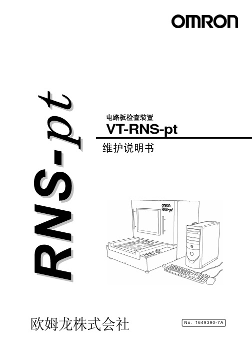
欧姆龙株式会社N o. 1649390-7A电路板检查装置VT-RNS-pt维护说明书前 言对贵公司这次购买本公司的电路板检查装置VT-RNS-ptH,谨表示衷心的感谢。
VT-RNS-pt是检查元件贴装状态和焊接状态,并将不良状态显示在显示器上的装置。
本说明书记载了使用VT-RNS-pt之际所必需的功能、性能、使用方法等信息。
在使用VT-RNS-pt之际,请您遵守以下事项。
·请仔细阅读本说明书,在充分理解的基础上正确使用。
·请妥善保管本说明书,以便随时参阅。
·关于装置的基本操作,请您仔细阅读使用相关说明书的相关内容,在充分理解的基础上正确使用。
●各位读者本说明书对基本操作和维护等进行说明。
其内容是面对参加过本公司举办的有关VT-RNS-pt研修培训的人员。
●对应装置本手册以电路板检查装置VT-RNS-ptH及电路板检查装置VT-RNS-ptS为对象进行记载。
VT-RNS-ptH与VT-RNS-ptS型,分别有相应的附带显示器的主机规格和显示器另置规格。
手册正文中记载为VT-RNS-pt。
电路板检查装置VT-RNS-pt维护说明书前言 承诺事项、安全注意事项、目录第1章 概要第2章 装置规格第3章 装置的移动与设置第4章 日常运转第5章 日常检查第6章 定期检查和维护第7章 消耗品一覧第8章 故障检修第9章 保管、报废使用时的承诺事项1.保修内容① 保修期间本产品的保修期间为购买后1年或提交给指定场所后1年。
② 保修范围在上述保修期间内,因本公司原因而导致本产品发生故障的情况下,可无偿进行故障品的更换及修理。
然而,故障的原因为如下情况时,将不在保修范围内。
a) 在产品目录、使用说明书和提交规格书等所记载内容以外的条件、环境、操作及使用方法下而导致故障时b) 本产品以外的原因而导致故障时c) 没有经由本公司而进行的改造或修理d) 没有按照本产品本来的使用方法来使用e) 本公司出厂时的科技水准所无法预见的情况时f) 因其它天灾和灾害等不属于本公司责任的原因时并且,在这里所说的保修指的仅为对本产品的保修,因本产品的故障而引发的损害不在保修范围之内。
卡特机operation and maintenance manual

Operation and Maintenance Manual3500B Series II and 3500C Marine Propulsion EnginesMedia Number -SEBU7844-13 Publication Date -01/02/2009 Date Updated -02/02/2009i03483840 Maintenance Interval ScheduleSMCS - 1000; 4450; 7500Ensure that all safety information, warnings and instructions are read and understood before any operation or any maintenance procedures are performed.The user is responsible for the performance of all maintenance which includes the following items: performing all adjustments, using proper lubricants, fluids, and filters and replacing old components with new components due to normal wear and aging .Failure to adhere to proper maintenance intervals and procedures may result in diminished performance of the product and/or accelerated wear of components.Before each consecutive interval is performed, all maintenance from the previous intervals must be performed.Use fuel consumption, service hours, or calendar time, WHICH EVER OCCURS FIRST, in order to determine the maintenance intervals. Products that operate in severe operating conditions may require more frequent maintenance.All of the following will affect the oil change interval: operating conditions, fuel type, oil type and size of the oil sump . Scheduled oil sampling analyzes used oil in order to determine if the oil change interval is suitable for your specific engine.In the absence of scheduled oil sampling, replace the engine oil and filters according to the following intervals:If the engine has a standard oil sump, change the oil after every 500 service hours.If the engine has a deep oil sump, change the oil after every 1000 service hours.Refer to this Operation and Maintenance Manual, "Engine Oil and Filter - Change" in order to determine the oil change interval that is suitable for your specific engine.To determine the maintenance intervals for the overhauls, refer to this Operation and Maintenance Manual, "Maintenance Recommendations" .When RequiredBatteries - ReplaceBattery or Battery Cable - DisconnectCentrifugal Oil Filter - InspectEngine Air Cleaner Element (Dual Element) - Clean/ReplaceEngine Air Cleaner Element (Single Element) - Clean/ReplaceFuel System - PrimeHeat Exchanger - InspectMaintenance RecommendationsSea Water Strainer - Clean/InspectZinc Rods - Inspect/ReplaceDailyAir Starting Motor Lubricator Oil Level - CheckAir Tank Moisture and Sediment - DrainCooling System Coolant Level - CheckDriven Equipment - Inspect/Replace/LubricateEngine Air Cleaner Service Indicator - InspectEngine Oil Filter Differential Pressure - CheckEngine Oil Level - CheckFuel System Fuel Filter Differential Pressure - CheckFuel System Primary Filter/Water Separator - DrainFuel Tank Water and Sediment - DrainInstrument Panel - InspectMarine Transmission Oil Level - CheckWalk-Around InspectionInitial 250 Service HoursEngine Speed/Timing Sensor - Clean/InspectEngine Valve Lash - AdjustFuel Injector - Inspect/AdjustEvery 250 Service HoursBattery Electrolyte Level - CheckBelts - Inspect/Adjust/ReplaceCooling System Coolant Sample (Level 1) - ObtainCooling System Supplemental Coolant Additive (SCA) - Test/AddEngine Oil Sample - ObtainEngine Oil and Filter - ChangeHoses and Clamps - Inspect/ReplaceInitial 500 Hours (for New Systems, Refilled Systems, and Converted Systems) Cooling System Coolant Sample (Level 2) - ObtainEvery 500 Service HoursAir Shutoff - TestEngine Oil and Filter - ChangeEvery 1000 Service HoursAir Starting Motor Lubricator Bowl - CleanEngine - CleanEngine Crankcase Breather - CleanEngine Oil and Filter - ChangeEngine Protective Devices - CheckFuel System Primary Filter/Water Separator - Clean/ReplaceFuel System Secondary Filter - ReplaceEvery 2000 Service HoursAir Starting Motor Lubricator Bowl - Clean Crankshaft Vibration Damper - InspectDriven Equipment - CheckEngine Mounts - CheckTurbocharger - InspectEvery YearCooling System Coolant Sample (Level 2) - Obtain Every 3000 Service Hours or 3 YearsCooling System Coolant (DEAC) - ChangeCooling System Coolant Extender (ELC) - AddEvery 4000 Service HoursAuxiliary Water Pump - InspectEngine Valve Lash - AdjustFuel Injector - Inspect/AdjustEvery 6000 Service HoursAir Shutoff Damper - Remove/CheckCooling System Water Temperature Regulator - Replace Every 6000 Service Hours or 6 YearsAir Starting Motor - InspectCooling System Water Temperature Regulator - Replace Electric Starting Motor - InspectEngine Speed/Timing Sensor - Clean/InspectPrelube Pump - InspectStarting Motor - InspectWater Pump - InspectEvery 8000 Service Hours or 3 Years Camshaft Roller Followers - InspectEvery 12 000 Service Hours or 6 Years Cooling System Coolant (ELC) - ChangeOverhaulAftercooler Core - Inspect/CleanOverhaul (Major)Overhaul (Top End)Overhaul ConsiderationsCopyright 1993 - 2009 Caterpillar Inc.Thu Jun 11 09:43:08 UTC+0200 2009 All Rights Reserved.Private Network For SIS Licensees.。
- 1、下载文档前请自行甄别文档内容的完整性,平台不提供额外的编辑、内容补充、找答案等附加服务。
- 2、"仅部分预览"的文档,不可在线预览部分如存在完整性等问题,可反馈申请退款(可完整预览的文档不适用该条件!)。
- 3、如文档侵犯您的权益,请联系客服反馈,我们会尽快为您处理(人工客服工作时间:9:00-18:30)。
C H-77H E L I C O P T E R S H E L I-S P O R T S.r.l.M A I N T E N N A A N N C C E E H H A A N N D D B B O O O O K KT H I R T T E E E E N N T T H H E E D D I I T T I I O O N NCH-7 HELI-SPORT MAINTENANCE CH-7 KOMPRESS 25 HOURS_____FOLLOWING MAINTENANCE HAS TO BE EXCUTED ONLY AFTER THE FIRST 25H FLIGHTDescription Q.ty Total Spare Parts Manufacture HOURS Oil transmission main gearbox, MRG filter and oil tail boxreplacement76,40 40,00 1 Oil free wheel replacement * 30,94 16,00 0,4 Clean air and fuel filter and fuel pump 33,16 40,00 1 Check and alignment of pulley and belt PLX025K 80,00 2ENGINE’S INSPECTION: CHECK UPDATED ROTAX’ MANUAL25H***** All prices in EURO, taxes excluded* If you utilize free wheel WARNER you can substitute the oil every 25 hIf you utilize new free wheel FORMSPRAG, you can substitute the oil every 100 hFOLLOWING MAINTENANCE HAS TO BE EXCUTED AFTER EACH 50 HDescription Q.ty Total Spare Parts Manufacture HOURS50H Clean air and fuel filter and fuel pump33,16 40,00 1 ENGINE’S INSPECTION: CHECK UPDATED ROTAX’ MANUAL***** All prices in EURO, taxes excludedFOLLOWING MAINTENANCE HAS TO BE EXCUTED AFTER 100 H FLIGHTDescription Q.tyTotalSpare PartsManufact HOURSCH61087 – viton ring for clutch 2 57,00PLX 3000 –bearing in clutch 1 52,84240,00 6 Oil transmission main gear box, MRG filter and oil tailbox replacement76,40 40,00 1 RC 01 – bearing replacement 2 11,28 80,00 2RC 08 – key replacement 2 174,00 80,00 2Optic fiber check transmission main box 20,000,5Oil free wheel replacement 30,94 16,000,4Oil and filter engine replacement - SEE ROTAXSplag replace NGKDPR9EA-9 – SEE ROTAX 8Vacum carburettor check and cable – SEE ROTAXGrease main rotor hub 8,29 12,000,3Check mapper setting and west gate 20,000,5Clean air and fuel filter and fuel pump 33,16 40,00 1Clean radiator 20,000,5Clean fuel tank 40,00 1Clutch way check 12,000,3Check and alignment of pulley and belt PLX025K80,00 2 General check by an expert 40,00 1Main rotor balance and tracking 552,61Tail rotor balance 248,68Fly check by an experienced pilot 193,41ENGINE’S INSPECTION: CHECK UPDATED ROTAX’ MANUALTOTAL SPARE PARTS + TOTAL MANUFACTURE 443,91 1.734,70100H***** total 100 H 2.178,61*****All prices in EURO, taxes excluded *****FOLLOWING MAINTENANCE HAS TO BE EXCUTED AFTER 200 H FLIGHTFOLLOWING MAINTENANCE HAS TO BE EXCUTED AFTER 300 H FLIGHTDescriptionQ.ty TotalSpare PartsManufacture HOURSSP 16 – bearing main box 2 110,40 SP 19 – bearing main box 1 64,46SP 32 – bearing main box 1 310,00 1.920,0048 CH61087 – viton ring for clutch 2 57,00 PLX 3000 – bearing in clutch152,84240,006Oil transmission main gear box, MRG filter and oil tail box replacement 76,4040,00 1 RC 01 – bearing replacement 2 11,2880,00 2 RC 08 – key replacement 2174,0080,002Optic fiber check transmission main box20,000,5Oil free wheel replacement 30,9416,000,4 Oil and filter engine replacement – SEEROTAX Splag replace NGKDPR9EA-9 – SEE ROTAX 8 Vacum carburettor check and cable – SEE ROTAX Grease main rotor hub 8,2912,000,3 Check mapper setting and west gate 20,000,5 Clean air and fuel filter and fuel pump 33,1640,00 1 Clean radiator 20,000,5 Clean fuel tank 40,00 1 Clutch way check 12,000,3 Check and alignment of pulley and belt PLX025K 80,00 2 General check by an expert 40,00 1 Main rotor balance and tracking 552,61 Tail rotor balance 248,68 Fly check by an experienced pilot193,41 ENGINE’S INSPECTION: CHECK UPDATED ROTAX’ MANUALTOTAL SPARE PARTS + TOTAL MANUFACTURE 928,77 3.654,70300 H100 H***** total 300 H4.583,47*****All prices in EURO, taxes excluded - *****CH-7 HELI-SPORT MAINTENANCE CH-7 KOMPRESS 400 HOURS____FOLLOWING MAINTENANCE HAS TO BE EXCUTED AFTER 400 H FLIGHTDescription Q.ty TotalSpare PartsManufact. HOURSRC30 – Bearing tail rotor 2 69,9680,00 2 RC33 – Bearing tail rotor 2 9,6880,00 2 SP 53b STARFLEX 2 66,3240,00 1 PLX 025k – Belt 1 378,5680,00 2 Uniball HM3 - Tail rotor control 2 91,08 80,00 2CH7020800 Tail rotor control rod1 348,15 40,00 1 CH61087 – viton ring for clutch2 57,00PLX 3000 – bearing in clutch1 52,84240,006 Oil transmission main gear box, MRG filter and oil tail box replacement76,40 40,001 RC 01 – bearing replacement2 11,28 80,002 RC 08 – key replacement 2 1 74,00 80,002 Optic fiber check transmission main box 20,000,5 Oil free wheels replacement30,94 16,000,4 Oil and filter engine replacement – SEE ROTAXSplag replace NGKDPR9EA-9 – SEE ROTAX 8 Vacuum carburettor check and cable – SEE ROTAXGrease main rotor hub8,2912,000,3 Check mapper setting and west gate 20,000,5 Clean air and fuel filter and fuel pump 33,16 40,00 1 Clean radiator 20,000,5 Clean fuel tank 40,00 1 Clutch way check12,000,3Check and alignment of pulley and belt PLX025K80,00 2 General check by an expert 40,00 1 Main rotor balance and tracking 552,61 Tail rotor balance248,68 Fly check by an experienced pilot193,41ENGINE’S INSPECTION: CHECK UPDATED ROTAX’ MANUAL TOTAL SPARE PARTS + TOTAL MANUFACTURE 1.407,66 1.814,70***** total 400 H 3.222,36 400 H100 H*****All prices in EURO, taxes excluded *****CH-7 HELI-SPORT MAINTENANCE CH-7 KOMPRESS 500 HOURS_____FOLLOWING MAINTENANCE HAS TO BE EXCUTED AFTER 500 H FLIGHTDescription Q.ty TotalSpare PartsManufacture HOURSPLX 029 – Bearing 2 99,80 80,00 2CH7021200 Front roller bearing rest 1 124,35 80,00 2 CH7021500 Rear roller bearing rest 1 124,35 80,00 2 CH7021300 Teflon guide 2 82,92 80,00 2CH7021400 Teflon guide 1 41,46 80,00 2CH61087 – viton ring for clutch 2 57,00PLX 3000 – bearing in clutch 1 52,84 240,00 6 Oil transmission main gear box, MRG filter and oil tail box replacement76,40 40,00 1 RC 01 – bearing replacement 2 11,28 80,00 2 RC 08 – key replacement 2 174,00 80,00 2 Optic fiber check transmission main box20,000,5 Oil free wheel replacement 30,94 16,000,4 Oil and filter engine replacement – SEE ROTAX Splag replace NGKDPR9EA-9 – SEE ROTAX 8 Vacum carburettor check and cable – SEEROTAX Grease main rotor hub 8,29 12,000,3 Check mapper setting and west gate 20,000,5 Clean air and fuel filter and fuel pump 33,16 40,00 1 Clean radiator 20,000,5 Clean fuel tank 40,00 1 Clutch way check 12,000,3 Check and alignment of pulley and belt PLX025K 80,00 2 General check by an expert 40,00 1 Main rotor balance and tracking 552,61 Tailrotor balance 248,68 Fly check by an expert pilot 193,41ENGINE’S INSPECTION: CHECK UPDATED ROTAX’ MANUALTOTAL SPARE PARTS + TOTAL MANUFACTURE 916,79 2.134,70500 H100 H***** total 500 H 3.051,49 ***All prices in EURO, taxes excluded***CH-7 HELI-SPORT MAINTENANCE CH-7 KOMPRESS 600 HOURS______FOLLOWING MAINTENANCE HAS TO BE EXCUTED AFTER 600 H FLIGHTDescription Q.ty TotalSpare PartsManufact. HOURSSP 45 – Pinion Axis1 1.384,29SP 24 – Crown1 1.326,26 280,007 Rubber main gearbox (SP AA + SP AB) 4+4 386,7680,00 2 MEK4 – Main rotor control rod4 849,0040,00 1 SP 44KW – Internal runway of free wheel 1 345,0080,00 2 SP 42KW- External tank of free wheel 1 810,0080,00 2 SP WY- Bearing free wheel box1 26,1040,00 1 SP 46 - CH7061100K Coupling sleeve 1 390,0040,00 1 SP 46A – Coupling sleeve 1 82,0080,00 2 SP43F – Free wheel WARNER 11.212,0080,00 2 RP 44 – Roll bearing2 52,1280,002 RP 60 – Bearing rod pitch transmission 4 49,5280,00 2 RP 65 – Bearing bolt lateral main rotor 2 41,3680,00 2 PLX 2000 – Bearing cyclic plate 2 545,0880,00 2 PLX 15 Bearing in cyclic plate2 13,2480,00 2 SP 1 – Bearing pulley 3 35,5880,00 2 SC 05 – Bearing tail box 4 46,5680,00 2 RC40 – CH710170A Tail rotor rod 2 315,7880,00 2RP58 – Mulbric bush4 45,9680,00 2 SP 16 – bearing main box 2 110,40 SP 19 – bearing main box 1 64,46 300 HSP 32 – bearing main box1 310,00 1.920,00 48 CH61087 – viton ring for clutch 257,00PLX3000- bearing in clutch1 52,84240,006Oil transmission main box, MRG filter and oil tail box replacement76,4040,00 1 RC 01 – bearing replacement 2 11,2880,00 2 RC 08 – key replacement 2 174,0080,00 2Optic fiber check transmission main box 20,000,5 Oil free wheel replacement 30,9416,000,4 Oil and filter engine replacement – SEE ROTAX Splag replace NGKDPR9EA-9 – SEE ROTAX8Vacum carburettor check and cable – SEE ROTAXGrease main rotor hub8,2912,000,3 Check mapper setting and west gate20,000,5 600 H100 HClean air and fuel filter and fuel pump33,1640,001Clean radiator 20,000,5 Clean fuel tank 40,00 1 Clutch way check 12,000,3 Check and alignment of pulley and beltPLX025K 80,00 2 General check by an expert 40,00 1 Main rotor balance and tracking 552,61Tail rotor balance 248,68Fly check by an experienced pilot 193,41 ENGINE’S INSPECTION: CHECK UPDATED ROTAX’ MANUALTOTAL SPARE PARTS+TOTALMANUFACTURE 9.230,78 5.174,70***** total 600 H 14.405,48***All prices in EURO, taxes excluded***CH-7 HELI-SPORT MAINTENANCE CH-7 KOMPRESS 700 HOURS_____FOLLOWING MAINTENANCE HAS TO BE EXCUTED AFTER 700 H FLIGHTDescription Q.tyTotalSpare PartsManufacture HOURSCH61087 – viton ring for clutch 2 57,00PLX 3000 – bearing in clutch152,84240,006Oil transmission main box. MRG Filter and oil tail box replacement76,4040,00 1 RC 01 – bearing replacement 2 11,2880,00 2 RC 08 – key replacement 2 174,0080,00 2 Optic fiber check transmission main box20,00 0,5 Oil free wheel replacement30,9416,000,4 Oil and filter engine replacement – SEE ROTAXSplag replace NGKDPR9EA-9 – SEE ROTAX 8Vacum carburettor check and cable – SEEROTAXGrease main rotor hub 8,2912,000,3 Check mapper setting and west gate 20,000,5Clean air and fuel filter and fuel pump 33,1640,001 Clean radiator 20,000,5 Clean fuel tank 40,00 1 Clutch way check 12,000,3 Check and alignment of pulley and belt PLX025K 80,002 General check by an expert 40,00 1 Main rotor balance and tracking 552,61 Tail rotor balance 248,68 Fly check by an expert pilot 193,41700H100 HENGINE’S INSPECTION: CHECK UPDATED ROTAX’ MANUALTOTAL SPARE PARTS + TOTAL MANUFACTURE 443,91 1.734,70***** total 700 H 2.178,61*****All prices in EURO, taxes excluded *****FOLLOWING MAINTENANCE HAS TO BE EXCUTED AFTER 800 H FLIGHTDescription Q.ty TotalSpare PartsManufact. HOURSRC30 – Bearing tail rotor 2 69,96 80,002 RC33 – Bearing tail rotor 2 9,68 80,002 SP 53b STARFLEX 2 66,32 40,001 PLX 025K – Belt 1 378,56 80,002 Uniball HM3 - Tail rotor control2 91,08 80,00 2 400 HCH7020800 Tail rotor control rod 1 348,15 40,001CH61087 – viton ring for clutch 257,00PLX 3000 – bearing in clutch1 52,84 240,00 6Oil transmission main box, MRG filter and oil tail box replacement76,4040,00 1 RC 01 – bearing replacement 2 11,2880,00 2 RC 08 – key replacement 2 174,0080,00 2 Optic fiber check transmission main box20,00 0,5 Oil free wheel replacement30,9416,000,4 Oil and filter engine replacement – SEE ROTAXSplag replace NGKDPR9EA-9 – SEE ROTAX 8Vacum carburettor check and cable – SEEROTAXGrease main rotor hub 8,2912,000,3 Check mapper setting and west gate 20,000,5 Clean air and fuel filter and fuel pump 33,1640,00 1 Clean radiator 20,000,5 Clean fuel tank 40,00 1 Clutch way check 12,000,3Check and alignment of pulley and belt PLX025K80,00 2 General check by an expert 40,00 1 Main rotor balance and tracking 552,61 Tail rotor balance 248,68 Fly check by an expert pilot 193,41800H100 HENGINE’S INSPECTION: CHECK UPDATED ROTAX’ MANUALTOTAL SPARE PARTS + TOTAL MANUFACTURE 1.407,661.814,70 ***** total 800 H3.222,36*****All prices in EURO, taxes excluded *****FOLLOWING MAINTENANCE HAS TO BE EXCUTED AFTER 900 H FLIGHTDescription Q.ty TotalSpare PartsManufacture HOURSSP 16 – Bearing main box 2 110,40 SP 19 – Bearing main box 1 64,46 SP 32 – Bearing main box 1 310,00 1.920,00 48CH61087 – viton ring for clutch 2 57,00PLX 3000 – bearing in clutch 1 52,84240,00 6 Oil transmission main box, Mrg filter and oil tailbox replacement76,4040,00 1 RC 01 – bearing replacement 2 11,2880,00 2 RC 08 – key replacement 2 174,0080,00 2 Optic fiber check transmission main box 20,000,5 Oil free wheel replacement 30,9416,000,4 Oil and filter engine replacement - SEE ROTAX Splag replace NGKDPR9EA-9 – SEE ROTAX 8 Vacum carburettor check and cable – SEEROTAXGrease main rotor hub 8,2912,000,3 Check mapper setting and west gate 20,000,5 Clean air and fuel filter and fuel pump 33,1640,00 1 Clean radiator 20,000,5 Clean fuel tank 40,00 1 Clutch way check 12,000,3 Check and alignment of pulley and belt PLX025K80,00 2 General check by an expert 40,00 1 Main rotor balance and tracking 552,61 Tail rotor balance 248,68 Fly check by an experienced pilot 193,41 ENGINE’S INSPECTION: CHECK UPDATED ROTAX’ MANUAL TOTAL SPARE PARTS + TOTAL MANUFACTURE 928,77 3.654,70900 H100 H 300 H***** Total 900 H 4.583,47 ***All prices in EURO, taxes excluded***FOLLOWING MAINTENANCE HAS TO BE EXCUTED AFTER 1000 H FLIGHTDescription Q.ty TotalSpare PartsManufacture HOURSPLX 029 – Bearing 2 99,80 80,00 2 CH7021200 – Front roller bearing rest 1 124,35 80,00 2 CH7021500 - Rear roller bearing rest 1 124,35 80,00 2 CH7021300 - Teflon guide 2 82,92 80,00 2 500 HCH7021400 - Teflon guide 1 41,46 80,00 2CH61087 – viton ring for clutch 2 57,00 PLX 3000 – clutch bearing 1 52,84 240,00 6 Oil transmission main box, MRG filter and oil tail box replacement 76,40 40,00 1 RC 01 – bearing replcement 2 11,28 80,00 2 RC 08 – key replacement 2 174,00 80,00 2 Optic fiber check transmission main box 20,000,5 Oil free wheel replacement 30,94 16,000,4 Oil and filter engine replacement – SEE ROTAX Splag replace NGKDPR9EA-9 – SEE ROTAX 8 Vacum carburettor check and cable – SEEROTAXGrease main rotor hub 8,29 12,000,3 Check mapper setting and west gate 20,000,5 Clean air and fuel filter and fuel pump 33,16 40,00 1 Clean radiator 20,000,5 Clean fuel tank 40,00 1 Clutch way check 12,000,3 Check and alignment of pulley and belt PLX025K80,00 2 General check by an expert 40,00 1 Main rotor balance and tracking 552,61 Tail rotor balance 248,68 Fly control by an experienced pilot 193,411000 HENGINE’S INSPECTION: CHECK UPDATED ROTAX’ MANUAL100 HTOTAL SPARE PARTS+TOTAL MANUFACTURE 916,79 2.134,70***** total 1000 H 3.051,49***** All prices in EURO, taxes excluded *****CH-7 HELI-SPORT MAINTENANCE CH-7 KOMPRESS 1100 HOURS_____FOLLOWING MAINTENANCE HAS TO BE EXCUTED AFTER 1100 H FLIGHTDescription Q.ty TotalSpare PartsManufacture HOURSCH61087 – viton ring for clutch 2 57,00 PLX 3000 – clutch bearing 1 52,84 240,00 6Oil transmission main box, MRG filter and oil tail box replacement 76,40 40,00 1 RC 01 – bearing replacement 2 11,28 80,00 2 RC 08 – key replacement 2 174,00 80,00 2 Optic fiber check transmission main box 20,000,5 Oil free wheel replacement 30,94 16,000,4 Oil and filter engine replacement – SEEROTAX Splag replace NGKDPR9EA-9 – SEE ROTAX 8 Vacum carburettor check and cable – SEEROTAXGrease main rotor hub 8,29 12,000,3 Check mapper setting and west gate 20,000,5 Clean air and fuel filter and fuel pump 33,16 40,00 1 Clean radiator 20,000,5 Clean fuel tank 40,00 1 Clutch way check 12,000,3 Check and alignment of pulley and belt PLX025K 80,00 2 General check by an expert 40,00 1 Main rotor balance and tracking 552,61 Tail rotor balance 248,68 Fly check by an experienced pilot 193,41ENGINE’S INSPECTION: CHECK UPDATED ROTAX’ MANUALTOTAL SPARE PARTS + TOTAL MANUFACTURE 443,91 1.734,701100 H100 H***** total 1100 H 2.178,61***All prices in EURO, taxes excluded***CH-7 HELI-SPORT MAINTENANCE CH-7 KOMPRESS 1200 HOURS_______FOLLOWING MAINTENANCE HAS TO BE EXCUTED AFTER 1200 H FLIGHTDescription Q.ty TotalSpare PartsManufacture HOURSHM4 – Tail rotor control10 474,30 200,00 5 MEK4 – Cyclic control 10 2.122,50200,00 5 ART5E (ME5) uniball 1 218,4020,000,5 ARYT4E (HXAM-04T) uniball 1 134,2020,000,5 RP9 – Bearing main blade hub 4 336,88 80,002RP12 – Bearing main blade hub 2 22,64 80,002RP8 – Bearing main blade hub 2 166,4480,00 2 SC 14 – Driver gear 1 810,2640,00 1 SC 8 – Conductor axis of tail rotor 1 810,2640,00 1 CH7011014 – Elastomer 16 369,60240,00 6 RC 11 – Bearing 2 56,9280,00 2 RC 16 – Bearing 1 15,0280,00 2 PLX 002 2 33,7280,00 2 PLX 003 6 65,6480,00 2 RP 48 - Mast 1 1.393,6480,00 2 RP49 – Lateral plate of main rotor 2 1.591,5280,00 2 CH7020300k – Tail rotor propeller shaft 1 331,5780,00 2 CH7016001 Strut tube 2 1.591,50 80,00 2 Frame and all steel component painting3.000,00Check blades main rotor Check blades main rotor Engine TBO by Rotax dealer (SEE ROTAX)MEK 4 – Clutch4 849,00 80,00 2 CH7008006 – Gear connection coupling pipe2 245,3440,00 1 CH7070200 Main blade hub 2 2.420,42 40,00 1 CH7070500 Blade axis nut 2 172,42 40,00 1 CH7070800 Blade hub nut 2 480,76 40,00 1 CH7070700 Blade axis2 2.540,86 40,00 1CH7071900K Main rotor stump 1 693,0040,001 Turbine Inspection by RotaxSP 45 – Pinion axis 1 1.384,29 SP 24 – crown 1 1.326,26 280,007 Rubber main box 4+4 386,7680,002 MEK4 – Main rotor control rod4 849,00 40,00 1 SP 44KW – Internal runway of free wheel 1 345,00 80,00 2 SP 42KW- External tank of free wheel 1 810,00 80,00 2 SP WY- 16009 bearing free wheel box 1 26,10 40,00 1 SP 46 - CH7061100K Coupling sleeve 1 390,00 40,00 1 SP 46A – Coupling sleeve 1 82,00 80,00 2 1200 H600 HSP43F – Free wheel WARNER11.212,0080,002RP 44 – Roll bearing 2 52,1280,002RP 60 – Bearing rod pitch transmission 4 49,5280,002 RP 65 – Bearing bolt lateral main rotor 2 41,3680,00 2 PLX 2000 – Bearing cyclic plate 2 545,0880,00 2 PLX 15 Bearing in cyclic plate 2 13,2480,00 2 SP 1 – Bearing pulley3 35,5880,00 2 SC 05 – Bearing tail box 4 46,56 80,00 2 RC40 – CH710170A Tail rotor rod 2 315,78 80,00 2RP58 – Mulbric bush 4 45,96 80,00 2 RC30 – Bearing tail rotor 2 69,9680,00 2 RC33 – Bearing tail rotor 2 9,6880,00 2 SP 53b STARFLEX 2 66,3240,00 1 PLX 025K – Belt 1 378,5680,00 2Uniball HM3 - Tail rotor control 2 91,08 80,00 2400 HCH7020800 Tail rotor control rod 1 348,15 40,00 1 SP 16 – Bearing main box 2 110,40SP 19 - Bearing main box 1 64,46300 HSP 32 - Bearing main box 1 310,00 1.920,0048CH61087 – viton ring for clutch 2 57,00PLX 3000 – Bearing in clutch 1 52,84240,00 6Oil transmission main box, MRG filter and oil tail box replacement 76,40 40,00 1 RC 01 – bearing replacement 2 11,28 80,00 2 RC 08 – key replacement 2 174,00 80,00 2 Optic fiber check transmission main box 20,000,5 Oil free wheel replacement 30,94 16,000,4 Oil and filter engine replacement – SEEROTAXSplag replace NGKDPR9EA-9 – SEEROTAX8 Vacum carburettor check and cable – SEEROTAXGrease main rotor hub 8,29 12,000,3 Check mapper setting and west gate 20,000,5 Clean air and fuel filter and fuel pump 33,16 40,00 1 Clean radiator 20,000,5 Clean fuel tank 40,00 1 Clutch way check 12,000,3 Check and alignment of pulley and belt PLX025K 80,00 2 General check by an expert 40,00 1 Main rotor balance and tracking 552,61 Tail rotor balance 248,68 Fly check by an experienced pilot 193,41 ENGINE’S INSPECTION: CHECK UPDATED ROTAX’ MANUAL TOTAL SPARE PARTS + TOTAL MANUF 31.141,567.414,70100 H ***** total 1200 H 38.556,04 ***All prices in EURO, taxes excluded***。