VC 230温湿度表说明书
Лакрос 温湿度监测器用户指南 说明书
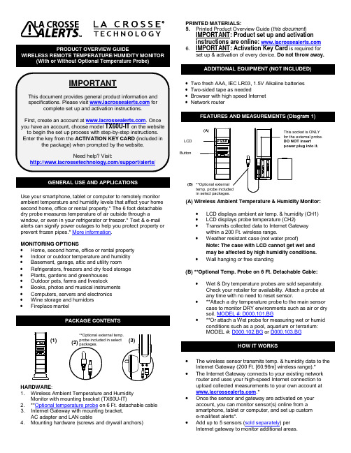
GENERAL USE AND APPLICATIONSUse your smartphone, tablet or computer to remotely monitor ambient temperature and humidity levels that affect your home second home, office or rental property.* The 6 foot detachable dry probe measures temperature of air outside through a window, or even in your refrigerator or freezer.* Text & e-mail alerts can signify power outages to help you protect property or prevent frozen pipes.* More information.MONITORING OPTIONS•Home, second home, office or rental property•Indoor or outdoor temperature and humidity •Basement, garage, attic and utility room •Refrigerators, freezers and dry food storage•Plants, gardens and greenhouses•Outdoor pets, farms and livestock•Books, photos and musical instruments•Computers, servers and electronics•Wine storage and humidors•Fireplace mantelPACKAGE CONTENTSHARDWARE:1. Wireless Ambient Temperature and HumidityMonitor with mounting bracket (TX60U-IT)2. **Optional temperature probe on 6 Ft. detachable cable3. Internet Gateway with mounting bracket,AC adapter and LAN cable4. Mounting hardware (screws and drywall anchors) PRINTED MATERIALS:5. Printed Product Overview Guide (this document)IMPORTANT: Product set up and activationinstructions are online: 6. IMPORTANT: Activation Key Card is required forset up & activation of every device. Do not throw away.•Two fresh AAA, IEC LR03, 1.5V Alkaline batteries•Two-sided tape as needed•Browser with high speed Internet•Network routerFEATURES AND MEASUREMENTS (Diagram 1)(A) Wireless Ambient Temperature & Humidity Monitor:•LCD displays ambient air temp. & humidity (CH1)•LCD displays probe temperature (CH2)•Transmits collected data to Internet Gatewaywithin a 200 Ft. wireless range.•Weather resistant case (not water proof)Note: The case with LCD cannot get wet andmay be affected by high humidity conditions.•Wall hanging or free standing(B) **Optional Temp. Probe on 6 Ft. Detachable Cable:•Wet & Dry temperature probes are sold separately.Check your retailer for availability. Attach a probe atany time with no need to reset sensor.•**Attach a dry temperature probe to the main sensorcase to monitor DRY environments such as air or drysoil. MODEL #: D000.101.BG•**Or attach a Wet probe for measuring wet or humidconditions such as a pool, aquarium or terrarium:MODEL #: D000.102.BG or D000.103.BGHOW IT WORKS•The wireless sensor transmits temp. & humidity data to theInternet Gateway (200 Ft. [60.96m] wireless range).*•The Internet Gateway connects to your existing networkrouter and uses your high-speed Internet connection toupload collected measurements to your own account at.*•Once the sensor and gateway are activated on youraccount, you can monitor sensor(s) online from asmartphone, tablet or computer, and set up custome-mail/text alerts*.•Add up to 5 sensors (sold separately) perInternet gateway to monitor additional areas.(1) (2)(B)**Optional externalin select packages.**1. Begin set up near your existing network router and a computer with high-speed Internet access.2. Unpack package contents and insert the temperature probe into the TX60U-IT case (see diagram 1).1. Locate the Activation Key Card in the package for setupinstructions and the Activation Key . A unique Activation Key is necessary to activate your sensor and InternetGateway. Please keep your Activation Card for reference. 2. Visit with your Activation KeyCard to create your account and activate the product.ACTIVATION INFORMATION:THE INCLUDED ACTIVATION KEY is good for1 year of ENHANCED SERVICE with early warning text & e-mail alerts, plus 4 more years of BASIC SERVICE for standard remote monitoring for a total of 5 years.Lost your Activation Key Card?Contact Customer Support:/support/alerts Phone: (608) 785-7920Once the sensor is activated and building a measurement log, you can download the data as a comma separated values (CSV) file. You must use an application such as Microsoft Excel® or Google Docs® that supports comma separated values (CSV) formatted files to view the table data.• Select a location protected from water and otherprecipitation. The case is water resistant, not water proof. • Place the sensor in a dry, shaded area. Avoid locations with direct sun, to prevent inaccurate readings.• Fog and mist will not harm the sensor but direct precipitation must be avoided.• Note: Exposing the sensor case to extreme humidity may temporarily disrupt data. The sensor case reads humidity, but should not be submerged in water.• Select a location within range of the Internet gateway (see “IMPORTANT SETUP & OPERATION NOTES”).• IMPORTANT: Before permanently mounting…Test sensor in the desired mounting location for at least 1 hour to confirm good reception. Confirm consistent readings on your account at before permanently mounting. Move the sensor closer to the Internet Gateway if the signal is lost or not received. • Mount the sensor after the activation process (see “SETUP AND ACTIVATION”).MOUNT TO WALL WITH SCREWS1. Remove the mounting bracket2. Place bracket over the desired location.3. Mark mounting surface with a pencil through the 2 holes of the bracket.4. Screw bracket onto surface and tighten screws to bracket.5. Insert the sensor back into the bracket.FREE STANDINGAttach the mounting bracket to the bottom or top of the sensor and place it on any flat surface.PLACEMENT OF TEMPERATURE PROBE (Optional)• Confirm that the end of the probe cable is secured in the socket inside the sensor (See Diagram 1).• Insert the dry temperature probe MODEL #: D000.101.BG on 6 Ft. cable into a refrigerator or freezer, or dry soil, etc. for a separate reading of air or soil temperature.• The dry temperature probe wire is not for use in water. **An optional wet probe should be used to measure wet environments (sold separately). Check your retailer for availability: MODEL #: D000.102.BG or D000.103.BG• Loosely coil and secure extra cord with a twist tie or secure with tape (not included).• The sensor has a wireless range of 200 feet (60.96 m). The 200 ft. range equates to open air with no obstructions, and that radio waves DO NOT curve around objects. Actualtransmission range will vary depending on what is in the path of the signal. Each obstruction (roof, walls, floors, ceilings, etc.) will effectively cut signal range in half.• Metal, stucco, and some types of glass can reduce signal range by as much as ¾ or more, compared to the ½ reduction typical of most obstructions. It is possible toreceive a signal through these materials, however maximum range will be reduced due to their tendency to absorb or reflect a much larger portion of the sensor’s signal.• The sensor measures and updates the temperature and humidity on the LCD every 6 seconds.Note : The new measurement is reported to your account at intervals that you select using your online account.1. Remove the battery cover by sliding the cover down.2. Observing the correct polarity install 2-AAA batteries. The batteries will fit tightly (to avoid start-up problems make sure they do not spring free).3. Do not mix old and new batteries.4. Do not mix alkaline, lithium, standard or rechargeable batteries.5. Replace the battery cover by sliding upwards and check that it is securely fitted.• Low battery icon appears on LCD when batteries are low. • You will receive an e-mail or mobile text message alert when the battery power of the sensor is low. Change the batteries immediately.Note: The LED light turns ON briefly after changing batteries. The LED light turns OFF when not needed to save battery power. The previously stored information in the temperature and humidity sensor will not be affected or cancelled while you change the batteries.• Avoid extreme temperatures, vibration and shock. • Clean the sensor with a soft, damp cloth. Do not use solvents or scouring agents.• Do not submerge the sensor case in water. • Do not kink the 6 ft. sensor cable.• Secure the 6 ft. cable to avoid tripping hazards.• Immediately remove all low powered batteries to avoid leakage and damage.• Opening the casings invalidates the warranty. Do not try to repair the unit. Contact La Crosse Technology® for repairs: /support/alerts . Temperature range:-40°F to 140°F with 0.2°F resolution“OFL” displayed if outside this range. Humidity measuring range: 3% to 99% Transmission range:200 feet (60.96 m) in open space*Optional Temp. Probe: Channel 2:-40°F to 140°F with 0.2°F resolution “OFL” displayed if outside this range, and displayed “nC” if probe is not connected.Sensor battery power 2 x AAA Alkaline, IEC LR03, 1.5V Internet gateway power: AC adapter (included) Battery life cycle:Approximately 24 monthsTX60U-IT size: 5.23" H x 0.76" W x 1.44" DSee the entire product line including temp./humidity monitors, water leak detectors and remote weather stations at: /alerts/La Crosse Technology, Ltd provides a 1-year limited warranty on this product against manufacturing defects in materials and workmanship. This limited warranty begins on the original date of purchase, is valid only on products purchased and used in North America and only to the original purchaser of this product. To receive warranty service, the purchaser must contact La Crosse Technology, Ltd for problem determination and service procedures. Warranty service can only beperformed by a La Crosse Technology, Ltd authorized service center. The original dated bill of sale must be presented upon request as proof of purchase to La Crosse Technology, Ltd or La Crosse Technology, Ltd’s authorized service center.La Crosse Technology, Ltd will repair or replace this product, at our option and at no charge as stipulated herein, with new or reconditioned parts or products if found to be defective during the limited warranty period specified above. All replaced parts and products become the property of La Crosse Technology, Ltd and must be returned to La Crosse Technology, Ltd. Replacement parts and products assume the remainingoriginal warranty, or ninety (90) days, whichever is longer. La Crosse Technology, Ltd will pay all expenses for labor and materials for all repairs covered by this warranty. If necessary repairs are not covered by this warranty, or if a product isexamined which is not in need or repair, you will be charged for the repairs or examination. The owner must pay any shipping charges incurred in getting your La Crosse Technology, Ltd product to a La Crosse Technology, Ltd authorized service center. La Crosse Technology, Ltd will pay ground returnshipping charges to the owner of the product to a USA address only.Your La Crosse Technology, Ltd warranty covers all defects in material and workmanship with the following specifiedexceptions: (1) damage caused by accident, unreasonable use or neglect (including the lack of reasonable and necessary maintenance); (2) damage occurring during shipment (claims must be presented to the carrier); (3) damage to, ordeterioration of, any accessory or decorative surface; (4)damage resulting from failure to follow instructions contained in your owner’s manual; (5) damage resulting from theperformance of repairs or alterations by someone other than an authorized La Crosse Technology, Ltd authorized service center; (6) units used for other than home use (7) applications and uses that this product was not intended or (8) the products inability to receive a signal due to any source of interference.. This warranty covers only actual defects within the product itself, and does not cover the cost of installation or removal from a fixed installation, normal set-up or adjustments, claims based on misrepresentation by the seller or performance variations resulting from installation-related circumstances.LA CROSSE TECHNOLOGY, LTD WILL NOT ASSUMELIABILITY FOR INCIDENTAL, CONSEQUENTIAL, PUNITIVE, OR OTHER SIMILAR DAMAGES ASSOCIATED WITH THE OPERATION OR MALFUNCTION OF THIS PRODUCT. THIS PRODUCT IS NOT TO BE USED FOR MEDICAL PURPOSES OR FOR PUBLIC INFORMATION. THIS PRODUCT IS NOT A TOY. KEEP OUT OF CHILDREN’S REACH.This warranty gives you specific legal rights. You may also have other rights specific to your State. Some States do not allow the exclusion of consequential or incidental damages therefore the above exclusion of limitation may not apply to you. For warranty work, technical support, or information, please contact:La Crosse Technology, Ltd2817 Losey Blvd. S. La Crosse, WI 54601/support/alertsLost your Activation Key Card?Contact Customer Support:/support/alerts Phone: (608) 785-7920* Disclaimers: La Crosse Technology, LTD. (“La Crosse”) provides various alert and monitoring services to aid users. (1) Service providers may charge users for alert services. Standard messaging and data rates apply and will be billed to the customer’s wireless account. Customers may be unable to receive text messaging or data service in some areas due to unavailability of service. (2) La Crosse shall not be liable for accuracy, usefulness or availability of data transmitted via the service. Users are solely responsible for damages to persons or property by service use.All rights reserved. This handbook must not be reproduced in any form, even in excerpts, or duplicated or processed using electronic, mechanical or chemical procedures without written permission of the publisher.This handbook may contain mistakes and printing errors. The information in this handbook is regularly checked and corrections made in the next issue.We accept no liability for technical mistakes or printing errors, or their consequences. All trademarks and patents are acknowledged.5,978,738 6,076,044 6,597,990This device complies with part 15 of the FCC rules. Operation is subject to the following two conditions:1) This device may not cause harmful interference.2) This device must accept any interference received,including interference that may cause undesired operation.LT012714。
室温控制器II 230V快速说明说明书

Room thermostat II 230 V quick instructionsProduct descriptionThe room thermostat II 230 V allows you to control your wired heating applications conveniently via your Smart Home system.Description of the symbolsWarning!Note about hazardsNote:Additionalimportant informationNote about the installation video8-750-002-395Safety instructions▶ R ead this user manual completely before installing or commissioning the device and pay particular attention to the hazard information.▶ T he installation of this device and work on the 230 V network must only be carried out by an electrician.▶ T he device is not a toy! Do not allow children to play with it. Never leave the packaging material lying around unattended. Plastic film and small parts may pose a danger to children.▶ T his device may be used by children from 8 years of age and by persons with reduced physical, sensory or mental capacities, or a lack of experience and knowledge provided these persons are supervised or have been instructed in the safe use of the device, and understand the corresponding risks.▶ W hen remotely or automatically controlling a device, it is not always possible to guarantee that commands are actually executed or that the correct device status is displayed in the app and on other Smart Home display devices because of external circumstances. This may lead to material damage and/or personal injury. Therefore, you must ensure to the greatest extent possible that no person is endangered at the time of remote operation or automated control. Please take special care when setting up or adjusting the remote control or when using the automated control and check the desired functionality at regular intervals.▶ D o not paint over the device! Do not apply wallpaper or paste over the device!▶ T he device is not suitable for disconnection.▶ F or safety and approval reasons (CE/UKCA), the device may not be modified and/or no changes may be made to the device without authorisation.▶ A ny use other than that which is described in the user manual is considered improper and leads to the exclusion of guarantee and liability.▶ W e accept no liability for material damage or personal injury which is caused by improper use or failure to observe the safety instructions. In these cases, any guarantee claim becomes void! We accept no liability for consequential damage.▶ D o not use the device if it has damage visible from the outside, for example, to the housing, control elements or connection sockets, or if it has a malfunction. If in doubt, please contact our service team.▶ O nly operate the device indoors and do not expose it to moisture, vibrations, constant sunlight or other sources of heat, extreme cold temperatures and mechanical stress.▶ D o not open up the device. It does not contain any parts to be maintained by the user. If a fault occurs, have the device checked by a specialist.▶ O nly use the device together with original components and recommended products from Bosch partners.▶ O nly operate the device with the control element attached.N otes▶ T he range within buildings can differ significantly from the range in open spaces. In addition to the transmitting power and the receiving properties of the receiver, environmental factors such as humidity, as well as the local structural situation, play an important role.▶ T he device is only intended for use in residential environments.▶ T he device is only intended for private use.Y ou can also use the explanatory videos andadditional information on our website as anadditional aid for mounting, installing, starting up and restoring the factory settings on yourBosch Smart Home room thermostat II 230 V: /rom/room-thermostat-2-230VProduct overviewLED display (2)The status LED (3) shows the status of the roomthermostat using flashing codes.Notes regarding installationT he standards and directives applicable in your country must be observed during planning,set-up, operation and maintenance.T he device is part of the building installation.Operation of the device is only permittedat 230 V/50 Hz AC voltage. Work on the230 V network may only be carried out by anelectrician. The applicable accident prevention regulations must be observed here. To avoidan electric shock on the device, please switchoff the mains power. Failure to observe theinstallation instructions may result in fire orother hazards.M ounting must be carried out following theapplicable requirements. Failure to observe the requirements may result in damage to property and/or injury, or even danger of death.P lease also note any additional information onthe product.A 230 volt alternating current power supply isrequired for this product (the device must havea phase and neutral conductor).T he product is only intended for fixedinstallation in in-wall switch boxes with aminimum depth of 35 mm and a screw distance of 60 mm (in accordance with DIN 49073-1) inindoor areas.T he supplied wire bridge (connection “COM”and “L” connections) may only be installed with 230 V AC consumers. Non-observance can lead to destruction of the device, fire or electrical accident!W hen connecting the device terminals, ensurethat permitted wires and wire cross sectionsare used.T he consumers connected to the relay outputs must have sufficient insulation.O bserve the technical data, in particularthe maximum permissible switching powerof the relay and the type of consumer to beconnected, before connecting a consumer.The device should only be loaded to thespecified power limit. Overloading may resultin destruction of the device, fire or an electrical accident. Among other things, reliableswitching off of the connected consumercannot be guaranteed.T he power circuit to which the device and theload are connected must be secured with acircuit breaker in accordance with EN 60898-1 (trigger characteristics B or C, max. 16 A rated current, min. 6 kA breaking capacity, energylimitation class 3). Installation guidelinesin accordance with the applicable nationalstandards, e. g. VDE 0100 or HD384 or IEC60364, must be observed. The circuit breakermust be easily accessible for the user andlabelled as a disconnecter for the device.W hen using the device in wet rooms such asbathrooms, a minimum distance of 60 cm from wet areas, such as a bathtub, shower or washbasin must be maintained.Installation and mountingB efore you start: Be sure to shut off the powercircuit breaker!If necessary, remove an existing thermostat. Connect the room thermostat II 230 V according to the connection diagram that suits you.Attach the in-wall housing to the wall box using suitable screws. Pay attention to correct orientation (Bosch writing at the top and readable): Place the control unit on the in-wall unit and press it in until it clicks into place.Now switch the power back on.As soon as the room thermostat is connected to the power supply, tuning mode starts and is active for 3 minutes. Tuning mode can be restarted at any timeby pressing the system button (4).T he room thermostat can also be operated independently, with no connection to the Smart Home system. The range of functions is then essentially limited to displaying and controlling the room temperature in conjunction with the connected heat generator according to the preset target temperature in the manual operating mode (without a time program).In the event that an initial start-up is required without a Smart Home system (e.g. new build), basic settings can be made on the device via an installer mode. To this end, press and hold the rotary knob (4) for at least 3 seconds until the display shows “INS”. By turning the knob (4) you can make a selection and confirm the selection by pressing it.A fter connecting the room thermostat to theBosch Smart Home system, you can also makeall device settings in the Smart Home app. Start-upEnsure that you have a Bosch Smart Home controller and the Bosch Smart Home app and have successfully configured both. Now start the Bosch Smart Home app and select “Add new device”. Follow the instructions in the app.Resetting to factory settingsYou can reset the device to its factory settings as follows:Remove the control unit from the in-wall housing. When reinserting it, hold the rotary knob (4) until “RES” appears on the display. Release the rotary knob and press it again. The device then restarts. Please note that it can take a few seconds until the room thermostat is ready for operation again.W hen resetting to factory settings, the settings and information are only lost from the deviceand not from the Bosch Smart Home controller.T o re-configure the device, first delete it in thedevice management section of the Bosch Smart Home app and then add it again in the usualconfiguring process.Maintenance and cleaningThe device does not require maintenance. Leave any repairs to a specialist. Clean the device with a soft, clean, dry and lint-free cloth. When cleaning, do not use any cleaning agents containing solvents. Simplified declaration of conformity Robert Bosch Smart Home GmbH herebydeclare that the radio equipment type Bosch Smart Home BTH-RM230Z corresponds with the directive 2014/53/EU. The complete text of the EU declaration of conformity is available via the following web address: https://Robert Bosch Smart Home GmbH hereby de-clares that the radio system type BTH-RM230complies with Regula tion 2017. The full text of the declaration of conformity is available at the follow-ing internet address: https:// Environmental protection and disposal Electrical or electronic devices which are nolonger usable must be collected separatelyand disposed of via an environmentally friendly recycling facility (European Directive on Waste Electrical and Electronic Equipment). Use your country’s specific return and collection systems when disposing of waste electrical or electronic devices.Technical dataDevice type designation BTH-RM230ZProtection type IP21Ambient temperature0 – 50 °CMax. humidity80 % (non-condensing)Housing dimensions (W × H × D)86 × 87 × 35 mmWeight131 gRadio protocol ZigBee 3.0Radio frequency 2.4 – 2.4835 GHzMax. transmitting power10 dBmRadio range in the open< 100 mSoftware class AReceiver category2Supply voltage230 V AC/50 HzMax. power consumption 1 AOverload protection Thermal cutoffCable type and cross section Rigid and flexible cable 1.0 – 1.5 mm²Installation In device sockets with a depth of at least 35 mm anda device screw spacing of 60 mmSwitch output Potential-free relayMax. switching power Ohmic load 3 A Inductive load 1 A Capacitive load –Mode of operation Type 1.BWithstand voltage3,000 VBall pressure test temperature125 °CDegree of soiling2Design Independently mounted, electronic control device Technical modifications reservedService informationRobert Bosch Smart Home GmbH Schockenriedstraße 17 70565 Stuttgart-Vaihingen Germany***************************@ /service8-750-002-395 V003 09/2022Spare parts / accessoriesFor information on available spare parts or accesso-ries, please visit:https:///rom/ spareparts。
Huato HT-HE230A 温湿度记录仪 使用说明书

Termohigrómetro De PanelHT-HE230AOperation manual for HE2XXA series large screen Thermo-HygrometerProducts IntroductionHE2XXA Series large screen Thermo-Hygrometer developed by HUATO,which has high precision and recording functions.Adopt imported temperature humidity integrated sensor, fast response and good quality to assure the accuracy and stability.1.Features:�Fashionable and simple performance,firm structure,high accuracy.�Adopt LED digital tube display,clear and bright,visible distance is10~50meters.�Temperature humidity calibration function;values can be adjusted through buttons on the instruments.�Recording capacity:>=43000,RS232-USB interface.2.Applications:It has been widely applied in offices,hotel,canteens,school,factory,supermarket, warehousing,hospital,and indoor environment etc.3.Performance parameters:4.Starter:(1)Buttons and componentspower and plug OK buttonExternal sensor upward buttonTemperature display area downward buttonHumidity display area Menu function button5.Key usage:Key functionNormal mode:press enter setup mode,press enter temperature setting, press or button respectively to adjust the value.Key functionNormal mode:Press this key is invalid.Setting mode:Set a negative value.Key functionNormal mode:Press this key is invalid.Setting mode:Set a positive value.Key functionNormal mode:Press this key is invalid.Setting mode:Confirm button and enter the next step.For example:Standard temperature is16℃,humidity is66%RH,and the measuring temperature is15.3℃,humidity is66.8%RH.Then difference of temperature is-0.7℃, difference of humidity is+0.8%RH.Setting StepsSteps::first,press enter setup mode,then press enter temperaturedeviation setting statestate;;press to adjust the temperature is-0.7℃,press enterhumidity settings,and press to adjust the humidity value is+0.8%RH,then pressback to normal modeHUATO ELECTRONIC(SHENZHEN)CO.,LTD.Address:F3of Building A,Taohuayuan Technological Innovation Zone,Xixiang Street, Baoan District,Shenzhen,China.After-sales service hot-line:0086-755-29977880Fax:0086-755-29748856Website:(REV1.0)。
温湿度传感器AM2301B产品手册说明书

温湿度传感器应用范围暖通空调 、除湿器、测试及检测设备、消费品、汽车 、自动控制、数据记录器、气象站、家电、湿度调节、医疗及其他相关温湿度检测控制。
2• 数字输出,I C 接口• 优异的长期稳定性• 响应迅速、抗干扰能力强1:AM2301BAM2301B 产品手册*选配外壳1.0电子对新一代传感器做了宽电压及低功59.026.614.014.0±0.553.0此精度为出厂检验时,传感器在 25℃供电电压为3.3V 条件下的测试精度。
此数值不包括迟滞和非线性,并只适用于 非冷凝条件。
25℃和1m/s 气流条件下,达到一阶响应 63%所需时间。
正常工作范围:0-80%RH, 超出此范围,传感器读数会有偏差(在90%RH 湿度下 200 小时后,漂移<3%RH)。
如果传感器周围有挥发性溶剂、带刺激性气味的胶带、粘合剂以及包装材料,读数可能会偏高。
详细说明请参阅相关文件。
供电电流和功耗的最小值和最大值都是基于 V CC = 3.3V 和 T<60℃的条件。
平均值为每两秒中进行一次测量的数值。
响应时间取决于传感器基片的导热率。
123456传感器性能相对湿度温度±0±2±4±6±8±10图 2 25°C 时相对湿度的最大误差。
△R H (%RH )相对湿度(%RH )电气特性表2 电气特性。
表 1 湿度特性表表 3 温度特性表-40 -20 0 20 40 6080图 3 温度典型误差和最大误差。
温度(℃)△T℃包装信息表4 包装信息。
图6V CC =3.3V 时,典型的供电电流与温度的关系曲线(休眠模式)。
请注意,这些数据与显示值存在大约±25%偏差。
2.1 2.3 2.5 2.7 2.93.1 3.3 3.5电压(V CC )1 扩充性能10080604020图4工作条件温度(℃)5101520253035404550556065707580温度( ℃)图50~80℃范围内对应的湿度最大误差,单位:(%RH)相对湿度(%)范围最大范围常正电流(n A )电流I C C (n A )温度(℃)请注意:以上误差为以高精度露点仪做参考仪器测试的最大误差(不包括迟滞)。
数字温湿度模块AM2301说明书_V1_1

避免在含有以下气体的环境中使用:盐、二氧化硫、卤素气体、氨、酒精、乙二醇醚、醛等;
工作环境
建议使用温度范围-10℃-60℃,湿度范围 0-100%RH。超出建议的范围可能导致测量结果暂时性 漂移;本产品对光线不敏感,但长时间暴露在太阳光或则紫外线辐射中,同样加速老化;
三包服务
正常环境条件使用下,本产品 1 年内承诺三包服务。
典型值
0.1
%RH
99.9 %RH
±3
%RH
±0.1
<8
S
±0.5
<3
%RH/r
表1
温度
参数 分辨率 工作范围 精度 重复性 响应时间 迟滞 漂移
条件 最小 典型 最大 单位
0.1
℃
-20
80 ℃
±0.5
℃
±0.2
℃
1/e(63%) 1
S
±0.1
典型值
< 0.2
℃/r
表2
图1
图2
五、 电气特性
参数
条件
-23.4℃,16bit 数据为:1000 0000 1110 1010
2.4、时序说明
主机启动信号:主机(MCU)先拉低总线 1mS 左右,再释放总线 20~40uS,检测从机的应答信号。 从机应答信号:从机传感器收到启动信号后,先拉低总线 80uS 应答,再释放总线 80uS 表示即将进 入数据传输。 数据传输:释放总线 80uS,SDA 处于高电平后就进入数据传输,每 1bit 的数据由一个低电平时序
本产品的供电电压为3.3~6V,建议供电电压为5V。
1.2、串行数据(SDA)
SDA 引脚为三态结构,用于读、写传感器数据。
EVKB23vc

C3
0
代码 最小值
d0
0
d1
0
d2
-99
d3
0
d4
0
d5
0
最大值 r2
最大值 25.0 25.0 1 1 1
最大值 15.0 r2 199
最大值 199 199 199
最大值 99 1 99 99 1 99
d6
0
1
d7 dA 代码
A1 A4 A6 A7 代码
0 0 最小值
0.0 0.0 0 0 最小值
冷风机风机停机温度 [针对蒸发器传感器:F0= 1,2]
除霜和排水时, 冷风机风机工作状态 0 =不工作; 1 =强制工作
排水后冷风机风机延迟工作时间
数字输入参数
数字输入连接类型
0 =常开; 1 =常闭
门开关输入动作引发结果的最大工作时间 -1 = 与输入动作同步
数字输入工作类型
0 =无动作;
1 = 报警输入, 延时 i7 后闪烁显示“iA”[与输入同步] ;
15 99 最大值
99 99 199 199 最大值
F0
0
2
F1 F2 F3 代码 i1 i3
-99 0 0 最小值 0 -1
99 1 15 最大值 1 120
i5
0
5
i7
-1
120
单位 ℃/℉(1)
单位 ℃/℉(1) ℃/℉(1)
------单位 ℃/℉(1) ℃/℉(1) ℃/℉(1) 单位 min min sec 单位 hours --℃/℉(1) min --min
8. 工作设定点和参数
8.1 工作设定点 代码 最小值 最大值
r1
温湿度测量模块说明书

SC0083湿敏电容型温湿度测量模块使用手册深圳商斯达实业有限公司名称:深圳商斯达实业有限公司电话:0755-******** 83607652网址:/地址:深圳市福田区福华路福庆街鸿图大厦1602室制定2002.4.25 名称温湿度测量模块修定1 2002.5.8 修定2 型号SC0083深圳商斯达实业修定31、 适用范围电子、制药、粮食、仓储、烟草、纺织、气象等行业。
2、 形状型号 封装 形状 1SC0083有外壳见实物3、 电气参数(1)供电电压(Vin): DC5V ±5%(2)消耗电流: 约2mA(MAX 5mA) (3)使用温度范围: 0~80℃(4)使用湿度范围: 0~100%RH(可凝露) (5)湿度检测范围: 0~100%RH (6)保存温度范围: 0~85℃(7)保存湿度范围: 95%RH 以下(非凝露)(8)湿度检测精度: ±4%RH(条件:at25℃,60%RH,Vin=5.0V)输出电压范围:1.68~1.92V(9)标准湿度输出电压:(条件:at25℃,Vin=5.0V) 相对湿度(%RH) 0 102030405060708090 100 输出电压(V)0.3 0.60.91.21.51.82.12.42.73.0输出阻抗:5kΩ以下标准特性图在4页图4所示(10)温度检出特性: ±1℃(LM35集成温度传感器) 标准数据表4页图5所示 (11)温度依存性(参考): ±2%RH(Vin=5.00V DC,20-90%RH 25℃为基准,0-50℃范围) (12)电压依存性(参考): ±5%RH(at25℃,20-90%RHDC5V 基准,4.75-5.25V 范围)4、标准检测条件大气中、温度25℃、供给电压5.0V DC作为基准。
特性测定,测定前先把温湿度模块放入25℃/0%RH的干燥空气中放置5分钟,湿度发生装置发生湿度60%RH,放入温湿度模块5分钟后测出电压值。
LAUDA Variocool VC 1200过程恒温器 说明书

PRODUCT DATA SHEETStanding: 2022-04-27LAUDA Variocool VC 1200Process thermostat 230 V; 50 Hz Part Number: L000923LAUDA DR. R. WOBSER GMBH & CO. KG Laudaplatz 1 • 97922 Lauda-Königshofen • DE T + 49 (0) 9343 503-0 • F + 49 (0) 9343 503-222Kommanditgesellschaft: Sitz Lauda-Königshofen Registergericht Mannheim • HRA 560069Persönlich haftende Gesellschafterin:Geschäftsführer:Dr. Gunther Wobser (Vors.), Dr. Mario Englert,Dr. Ralf Hermann, Dr. Marc StrickerBeirat: Dr. Gerhard WobserR e s e r v e t e c h n i c a l c h a n g e sFeatures•Process thermostat suitable for use with non-flammable heat transfer liquids •Coloured TFT display for simultaneous indication of actual & set values and graphic illustration of the temperature profile•Clear text menu navigation, six selectable languages DE, EN, FR, ES, IT, RU •Easy input via cursor and soft keys•Fully electronic continuous controller with PID action •Electronic level indication and low level alarm •Powerful pressure pump •USB interface as standard•Remote fault indication through floating contact•Upgradeable with an interface module (analogue module, contact module, RS 232/485 module, Profibus, Ethernet-USB module)•Integrated programmer with max. 150 segments, splitable in 5 programmes •Adjustable bypass for pressure limiting•Filler opening on top, drain tap on the backside•SmartCool system for energy-saving digital cooling management including compressor on-off control •Operates with non flammable liquids (water,water/glycol)•Condenser cooling AirWorking temperature min.-20 °CWorking temperature max. 80 °CPRODUCT DATA SHEET Standing: 2022-04-27 LAUDA Variocool VC 1200Process thermostat 230 V; 50 HzPart Number: L000923LAUDA DR. R. WOBSER GMBH & CO. KG Laudaplatz 1 • 97922 Lauda-Königshofen • DET + 49 (0) 9343 503-0 • F + 49 (0) 9343 503-222Kommanditgesellschaft: Sitz Lauda-KönigshofenRegistergericht Mannheim • HRA 560069Persönlich haftende Gesellschafterin:Geschäftsführer:Dr. Gunther Wobser (Vors.), Dr. Mario Englert,Dr. Ralf Hermann, Dr. Marc StrickerBeirat: Dr. Gerhard Wobser R e s e r v e t e c h n i c a l c h a n g e sTechnical Features (according to DIN 12876)Working temperature range-20 ... 80 °CAmbient temperature range 5 ... 40 °CTemperature stability0.05 ± KHeater power max. 2.25 kWPower consumption max. 3.3 kWCurrent max.14 APump Pressure max. 3.2 barPump flow rate pressure max.37 L/minIn / Outlet connection thread (outside)G 3/4Pressure adjustement bypassFilling volume max.15 LOverall dimensions (WxDxH)450 x 550 x 790 mmWeight51 kgRefrigerant stage 1R-449A (GWP 1397); 0.500 kg; 0.7 t CO2-eq Power supply230 V; 50 HzPower plug Power cord with angled plug (CEE7/7)Temperature Heat transfer liquid Cooling Capacity 50 Hz20 °C Ethanol 1.12 kW10 °C Ethanol0.92 kW0 °C Ethanol0.62 kW-10 °C Ethanol0.32 kW-20 °C Ethanol0.06 kWPRODUCT DATA SHEET Standing: 2022-04-27 LAUDA Variocool VC 1200Process thermostat 230 V; 50 HzPart Number: L000923LAUDA DR. R. WOBSER GMBH & CO. KG Laudaplatz 1 • 97922 Lauda-Königshofen • DET + 49 (0) 9343 503-0 • F + 49 (0) 9343 503-222Kommanditgesellschaft: Sitz Lauda-KönigshofenRegistergericht Mannheim • HRA 560069Persönlich haftende Gesellschafterin:Geschäftsführer:Dr. Gunther Wobser (Vors.), Dr. Mario Englert,Dr. Ralf Hermann, Dr. Marc StrickerBeirat: Dr. Gerhard Wobser R e s e r v e t e c h n i c a l c h a n g e sStandard accessories• 2 nipples 3/4" with screw cap G3/4 for pump connectors。
- 1、下载文档前请自行甄别文档内容的完整性,平台不提供额外的编辑、内容补充、找答案等附加服务。
- 2、"仅部分预览"的文档,不可在线预览部分如存在完整性等问题,可反馈申请退款(可完整预览的文档不适用该条件!)。
- 3、如文档侵犯您的权益,请联系客服反馈,我们会尽快为您处理(人工客服工作时间:9:00-18:30)。
室内温湿度计用户手册
产品性能
环境舒适度显示: COMFORT(舒适)、WET(湿度高)、DRY(干燥)
温度测量范围:0℃~50℃(32℉~120℉)
温度测量精度:±1.0℃(1.8℉)
温度分辨率显示:0.1℃(0.1℉)
湿度测量范围:30%RH~90%RH
湿度测量精度:±5%(40%~80%)其它±8%
使用电池:AAA 1.5∨时间/温度/湿度显示
℃/℉温度的切换显示最高/最低温湿度记忆功能
日历显示、整点报时、每日闹钟功能12/24小时制时钟
功能设置
1.基本功能键:[MODE]时钟/闹钟切换,并可设置时钟、闹钟、日历[ADJ]调整设置项目的值/开关闹钟、显示日期,[MEMO]显示记忆中的最高、最低温湿度值,[℃/℉]切换温度℃/℉显示方式[RESET]清除所有设定和记忆返回初始状态。
2.时钟和日期设置:按住[MODE]3秒,分钟开始闪烁,按[ADJ]调节分钟。
再按[MODE]一下,时钟开始闪烁,按[ADJ]调节时钟。
再按[MODE]一下转换12/24小时,按[ADJ]调节。
再按[MODE]一下,月份开始闪烁,按[ADJ]调节。
再按[MODE]一下,日期开始闪烁,按[ADJ]调节。
再按一下[MODE]确认。
3.闹铃设置:按一下[MODE]键,显示闹铃的时间,再按住[MODE] 3秒,分钟开始闪烁,按[ADJ]调节分钟。
再按[MODE]一下,时钟开始闪烁,按[ADJ]调节时钟。
连续按两次[MODE] 确认。
闹铃启动和关闭:按一下[MODE]键,显示闹铃的时间,按一下[ADJ]键,出现”闹铃符号”。
再按一下[ADJ]键,出现”整点报时”符号。
再按一下[ADJ]键,两个符号同时出现,表示两种功能同时启用。
连续按[ADJ]键, 可以启用或关闭该功能,按[MODE]键确认。
4. 日历显示:在当前时钟状态下,按一下[ADJ]自动显示日期,3秒后返回。
5.最大/最小温湿度值显示,按[MEMO]可以显示记忆中温湿度最大值(MAX)和最小值、(MIN),按住2秒以上清除记忆值。
6. 环境舒适显示:当温度在20℃~26℃(68℉~78.8℉)之间,相对湿度在50%~70%RH之间是显示“舒适符号”及COMFORT 字符。
在任意温度下,湿度高于70%RH显示“湿度高符号”及WET字符。
在任意温度下,湿度低于50%RH显示“湿度低符号”及DRY字符。
注意事项
1.电池用完后请放回政府指定地点。
2.使用环境温度范围:0℃~50℃
3.本表不做为工业专用精确数剧测量,适合家庭居室使用。
MB-0230-00。