伏科太阳能充放电控制器
MPPT2024Z 太阳能充放电控制器使用手册说明书
MPPT2024Z 太阳能充放电控制器使用手册安装、使用前请仔细阅读该手册 武汉万鹏科技有限公司 h t t p ://w w w .j u t a s o l a r .c o m 武汉万鹏科技有限公司 ht t p ://w w w.j u t a s o l a r .c o m 科技有限公司t a s o l a r .c o mMPPT2024Z 太阳能充放电控制器使用手册 版本V1.1目录 1. 安全事项............................................................................................................3 2. MPPT2024Z 控制器介绍.....................................................................................3 2.1 产品概述..................................................................................................3 2.2 产品结构..................................................................................................3 2.3 产品功能..................................................................................................4 2.4 最大功率点跟踪(MPPT)技术介绍......................................................6 3.系统规划参考....................................................................................................7 3.1 系统电压等级..........................................................................................7 3.2 太阳能电池配置......................................................................................8 3.3 配线..........................................................................................................8 3.4 过流保护..................................................................................................9 3.5 雷击保护..................................................................................................9 3.6 接地..........................................................................................................9 3.7 系统扩容..................................................................................................9 4.安装说明..........................................................................................................10 4.1 产品外形尺寸........................................................................................10 4.2 系统接线示意图....................................................................................11 4.3 线材工具准备........................................................................................11 4.4 安装过程................................................................................................11 5.使用说明..........................................................................................................12 5.1 按键功能说明........................................................................................12 5.2 LED 指示状态说明.................................................................................12 5.3 系统类型查看........................................................................................13 6.故障处理..........................................................................................................13 6.1 控制器保护后处理方法........................................................................13 6.2 常见故障现象及处理方法....................................................................14 7.技术参数..........................................................................................................15 8. 保修承诺. (16)武汉万鹏科技有限公司 h tt p ://w w w .j u t a s o l a r .c o m 武汉万鹏科技有限公司 ht t p ://w w w.j u t a s o l a r .c o m 科技有限公司 t a s o l a r .c o mMPPT2024Z 太阳能充放电控制器使用手册 版本V1.1尊敬的用户: 非常感谢您选用我们公司的产品!我们将为您的太阳能发电系统提供长久可靠的服务! 该手册提供产品的安装、使用、维护等相关的指导,使用前请仔细阅读该手册。
太阳能充放电控制器MPPT5020-BT使用说明书

1. 2. 可通过拨码开关选择4种电池。
GEL 电池,铅酸(液体)电池,AGM 2电池,LiFePO4磷酸铁锂电池3. 带负载输出功能,具有过放,过载,短路保护功能。
4. 带蓝牙功能,可以通过手机APP 显示查看控制器参数(仅MPPT 5020-BT,MPPT5040-BT )5. 具有RS 485通信功能,便于终端设备可靠的读取到控制器的运行参数(仅6. 全自动无人值守充电。
具有过载,过热,反向电流保护(阴天或者晚上无阳光的时候,防止蓄电池倒灌到太阳能板)7. 过充保护。
当电池充满的时候 ,充电电流会减小,当蓄电池没电的时候,会立即给蓄电池充电8. 自动温度补偿功能。
确保电池在低温或者高温的环境下,采用最佳的充电参数,延长蓄电池的使用寿命强烈建议,不要把蓄电池和控制器安装在发热源的地方,以免引起控制器的误操作提高充电电流,相比传统的PWM 控制器,MPPT 充电效率可以提高10-30%。
(控制器转换效率>95%)MPPT 5020-COM,MPPT5040-COM)使用说明书太阳能充放电控制器MPPT1. 只能给符合额定电压的GEL 电池,铅酸液体电池,AGM 电池,磷酸铁锂(必须带MBS)电池充电2. 太阳能板功率尽量使用控制器最大额定功率以内的太阳能板3. 连接电缆的线径参考工厂的建议值。
如果电缆过小,会导致电缆过热和能量损耗4. 在靠近电池端的附近安装额定规格的保险丝,用来保护蓄电池和太阳能板之间的电缆5. 请安装在通风良好的房间内,防止雨水,潮湿,灰尘,侵蚀性的电池气体以及在环境没有冷凝水6. 本机出售时候,不配任何配件。
如果需要更换部品,请联系供应商7. 控制器和电池请远离儿童.带APP 显示或者RS485通信功能MPPT5020-BT MPPT5020MPPT5040MPPT5040-BT MPPT5020-comMPPT5040-com 适用 铅酸(液体,AGM ,GEL )电池 LiFePO4磷酸铁锂电池-1 2胶体电池(GEL )密封铅酸(Lead-acid )AGM↑↑↑↑Note:连接电缆的时候请仔细看清控制器上的标识,绝对不能把极性接错,否则可能导致控制器损坏。
太阳能充电控制器使用说明书

风光互补+LED 恒流一体机使用说明书■ 主要特点:1、本公司自主研发新型风光互补降压型MPPT + LED 升压型恒流一体机控制器;2、具有蓄电池浮充、涓充、过充、过放、反接保护;风机电子卸荷、转速检测、自动刹车、手动刹车保护;负载恒流输出、降功率调节、电子短路、过载保护;太阳能独特的防反接、防反充保护等全自动控制;以上保护均不损坏任何部件。
3、风力发电机采用独特的降压型MPPT 功能,具有转速检测、过速保护,风机过充自动卸荷、恒压、限流充电功能;风机转速和刹车恢复时间都可随意设定、修改;4、太阳能也采用了降压型MPPT 功能,串联式充电主回路,使充电回路的电压损失较使用二极管的充电电路降低近一半,充电效率较非PWM 高3%-6%,增加了用电时间;过放恢复的提升充电,正常的直充,浮充自动控制方式使系统有更长的使用寿命;同时具有高精度温度补偿。
5、负载使用升压型恒流方式,转换效率可达98%,可在线调整LED 输出电流,电流从30mA —3300mA 可调,并且可分四个时段,分别对亮灯时控、功率进行调节。
6、直观的LED 发光管指示当前系统运行状态,通过指示灯可以清楚的了解系统使用情况,以及故障报警状态。
7、所有控制全部采用工业级芯片,能在寒冷、高温、潮湿环境运行自如。
同时使用了晶振定时控制,定时控制精确。
8、使用了直观的LED 数码管显示设置,一键式操作即可完成所有设置,定时时间与数码管显示数字一一对应,显示更直观。
9、外壳防水采用独特的结构设计,使得外壳与散热片之间密封结合,只需将端子一面朝下安装,皆可起到安全的防水效果,顶端有安装挂件孔,即方便了安装,也起到了防水作用,同时大型散热片更加达到良好的散热效果,可有效延长控制器的使用寿命。
■ 控制器面板图:■ 系统说明:本控制器专为风力发电和太阳能发电直流供电系统、LED 照明设备设计专用,使用了专业电脑芯片的智能化控制。
采用一键式轻触开关,可完成所有操作及设置。
太阳能充电控制器操作手册 10.10 A 8.8 A 6.6 A说明书

Operating manualSolar charge controller10.10 A / 8.8 A / 6.6 APlease read these instructions completely before installation!1. About this manualThese operating instructions are part of the product. Read these operating instructions carefully before use, keep them over the entire lifetime of the product, and pass them on to any future owner or user of this product.This manual describes the installation, function, operation and maintenance of the solar charge controller. These operating instructions are intended for end customers.A technical expert must be consulted in cases of uncertainty.2. SafetyThe solar charge controller may only be used in PV systems for charging and controlling lead-acid batteries in accordance with this operating manual and the charging specifications of the battery manufacturer.The solar charge controller may only be connected to the local loads and the battery by trained personnel and in accordance with the applicable regulations. Follow the installation and operating instructions for all components of the PV system.No energy source other than a solar generator may be connected to the solar charge controller. Follow the general and national safety and accident prevention regulations.Keep children away from PV systems. Do not use the solar charge controller in dusty environments, in the vicinity of solvents or where inflammable gases and vapours can occur. No open fires, flames or sparks in the vicinity of the batteries. Ensure that the room is adequately ventilated. Check the charging process regularly.Follow the charging instructions of the battery manufacturer. Battery Acid splashes on skin or clothing should be immediately rinse with plenty of water. Seek medical advice.Do not operate the solar charge controller when it does not appear to function at all. The solar charge controller or connected cables are visibly damaged or loose. In these cases immediately remove the solar charge controller from the solar modules and battery.3. FunctionsThe solar charge controller monitors the state of charge of the battery bank, controls the charging process, controls the connection/disconnection of loads. This optimises battery use and significantly extends its service life.The following protection functions are part of the basic function of the controller: Overcharge protection ; Deep discharge protection ; Battery undervoltage protection ; Solar module reverse current protection.4. Installation4.1 Mounting location requirementsDo not mount the solar charge controller outdoors or in wet rooms. Do not subject the solar charge controller to direct sunshine or other sources of heat. Protect the solar charge controller from dirt and moisture.Mount upright on the wall (concrete) on a non-flammable substrate. Maintain a minimum clearance of 10 cm below and around the device to ensure unhindered air circulation. Mount the solar charge controller as close as possible to the batteries (with a safety clearance of at least 30 cm).4.2 Fastening the solar charge controllerMark the position of the solar charge controller fastening holes on the wall.Drill 4 Ø 6 mm holes and insert dowels. Fasten the solar charge controller to the wall with the cable openings facing downwards, using 4 oval head screws M4x40 (DIN 7996).4.3 ConnectionUse an wire size suited to the current ratings of the charge controller, e.g. 6mm² for 10A, 5 mm² for 8A, 4 mm² for 6A, 3 mm² for 5A for cable length of 10 m.An additional external 20A fuse (not provided) must be connected to the battery connection cable, close to the battery pole. The external fuse prevents cable short circuits.Solar modules generate electricity under incident light. The full voltage is present, even when the incident light levels are low. Protect the solar modules from incident light during installation, e.g. cover them.Never touch not isolated cable ends. Use only insulated tools. Ensure that all loads to be connected are switched off. If necessary, remove the fuse.Connections must always be made in the sequence described below.1st step: Connect the batteryInfo LED Battery LEDsConnect the battery connection cable with thecorrect polarity to the middle pair of terminalson the solar charge controller (with the batterysymbol).If present, remove any external fuse. Connectbattery connection cable A+ to the positivepole of the battery. Connect batteryconnection cable A– to the negative pole ofthe battery. Insert the external fuse in thebattery connection cable.If the connection polarity is correct, the infoLED illuminates green.2nd step: Connect the solar moduleEnsure that the solar module is protected from incident light (cover it or wait for night).Ensure that the solar module does not exceed the maximum permissible input current.First connect the M+ solar module connection cable to the correct pole of the left pair ofterminals on the solar charge controller (with the solar module symbol), then connect theM– cable. Remove the covering from the solar module.3rd step: Connect loadsFirst connect the L+ load cable to the correct pole of the right pair of terminals on the solarcharge controller (with the lamp symbol), then connect the L– cable. Insert the load fuse orswitch on the load.Notes : Connect loads that must not be deactivated by the solar charge controller deepdischarge protection, e.g. emergency lights or radio connection, directly to the battery.Loads with a higher current consumption than the device output can be directly connectedto the battery. However, the solar charge controller deep discharge protection will no longerintervene. Loads connected in this manner must also be separately fused.4th step: Final workFasten all cables with strain relief in the direct vicinity of the solar charge controller(clearance of approx. 10 cm).5. LED displaysLED Status Meaningilluminates green normal operationInfo LEDflashes slowly red* system fault- too high charging current- overload / short circuit- overheatedtogether with red LED :- too low battery voltagetogether with green LED :- too high battery voltageflashing quickly* battery empty, low voltage disconnectionprewarning, loads still onBatteryredLED flashing slowly* deep discharge protection active (LVD), loadsdisconnectedilluminates battery weak, loads are onBatteryyellowLEDflashes slowly yellow* LVD reconnection setpoint has not yet beenreached, loads still disconnectedilluminates battery goodBatterygreenLEDflashes slowly green* battery full, charge regulation active*flashing slowly: 0,4Hz: 4 times in 10 second, flashing quickly: 3Hz: 3 times in 1 second6. GroundingThe components in stand-alone systems do not have to be grounded – this is not standardpractice or may be prohibited by national regulations (e.g.: DIN 57100 Part 410: Prohibitionof grounding protective low voltage circuits). Ask your dealer for technical assistance.7. Lightning protectionIn systems subjected to an increased risk of overvoltage damage, we recommendinstalling additional lightning protection / overvoltage protection to reduce dropouts.Ask your dealer for technical assistance.8. MaintenanceThe solar charge controller is maintenance-free.All components of the PV system must be checked at least annually, according to thespecifications of the respective manufacturers. Ensure adequate ventilation of the coolingelement. Check the cable strain relief. Check that all cable connections are secure. Tightenscrews if necessary. Check corrosion on terminals.9. Faults and remediesNo display : Check battery polarity and external fuse. Or battery voltage is too low orbattery defective.Battery is not charged : Check if solar modul is connected with correct polarity or if shortcircuit at the solar input. If solar module voltage is lower than battery voltage or if solarmodule is defective the battery cannot be charged.Battery displays jumps quickly : Battery voltage changes quickly. Large pulse currentscause voltage fluctuation. Battery is too small or defective. Ask your dealer for technicalassistance.The following faults do not destroy the controller. After correcting the fault, the device willcontinue to operate correctly:* solar module short circuits * reverse solar module polarity *2* short circuits at load output * excessive load current* reversed battery polarity *1* solar module overcurrent* device overtemperature * overvoltage at the load output10. Legal guaranteeAccording to the German legal requirements, for this product the customer has a 2 yearlegal guarantee.The seller will remove all manufacturing and material faults that occur in the product duringthe legal guarantee period and affect the correct functioning of the product. Natural wearand tear does not constitute a malfunction.Legal guarantee does not apply if the fault can be attributed to third parties, unprofessionalinstallation or commissioning, incorrect or negligent handling, improper transport, excessiveloading, use of improper equipment, faulty construction work, unsuitable constructionlocation or improper operation or use.Legal guarantee claims shall only be accepted if notification of the fault is providedimmediately after it is discovered. Legal guarantee claims are to be directed to the seller.The seller must be informed before legal guarantee claims are processed.For processing a legal guarantee claim an exact fault description and the invoice / deliverynote must be provided. The seller can choose to fulfil the legal guarantee either by repair orreplacement.If the product can neither be repaired nor replaced, or if this does not occur within asuitable period in spite of the specification of an extension period in writing by thecustomer, the reduction in value caused by the fault shall be replaced, or, if this is notsufficient taking the interests of the end customer into consideration, the contract iscancelled. Any further claims against the seller based on this legal guarantee obligation, inparticular claims for damages due to lost profit, loss-of-use or indirect damages areexcluded, unless liability is obligatory by German law.11. Technical DataSteca Solsum F 6.6F 8.8F 10.10FSystem voltage 12 V (24 V)Own consumption < 4 mADC input sideOpen circuit voltage solar module(at minimum operating temperature)< 47 VModule current 6 A 8 A 10 ADC output sideLoad current 6 A 8 A 10 AEnd of charge voltage 13.9 V (27.8 V)Boost charge voltage 14.4 V (28.8 V)Reconnection voltage (SOC / LVR) *³> 50 % / 12.4 V … 12.7 V(24.8 V … 25.4 V)Deep discharge protection (SOC / LVD) *³< 30 % / 11.2 V … 11.6 V(22.4 V … 23.2 V)Operating conditionsAmbient temperature -25 °C … +50 °CFitting and constructionTerminal (fine / single wire) 4 mm2 / 6 mm2 - AWG 12 / 9Degree of protection IP 32Dimensions (X x Y x Z) 145 x 100 x 24 mmWeight approx. 150 g*1Solsum is protected against reverse battery polarity together with polarity protectedloads. Reverse battery polarity combined with short circuited or polarised load couldcause damages in load or regulator*2avoid reverse module polarity in a 24V system*3Lower value for nominal current, higher value for lowest currenManufactured in aDIN EN ISO 9001:2000 facilitySolsum / Z02 / Version 09.45/ 730.930。
太阳能控制器的作用和区别
太阳能控制器的作用和区别太阳能控制器全称为太阳能充放电控制器,是用于太阳能发电系统中,控制多路太阳能电池方阵对蓄电池充电以及蓄电池给太阳能逆变器负载供电的自动控制设备。
它对蓄电池的充、放电条件加以规定和控制,并按照负载的电源需求控制太阳电池组件和蓄电池对负载的电能输出,是整个光伏供电系统的核心控制部分。
太阳能控制器的作用太阳能控制器的基本功能是控制电池电压并打开电路,当电池电压上升到一定程度时,停止蓄电池充电。
在大多数光伏系统中都用到了控制器以保护蓄电池免于过充或过放。
过充可能使电池中的电解液汽化,造成故障,而电池过放会引起电池过早失效,过充过放均有可能损害负载,所以控制器是光伏发电系统的核心部件之一,也是平衡系统BOS(Balance Of System)的主要部分。
简单来说,太阳能控制器的作用可以分为:1、功率调节功能。
2、通信功能:简单指示功能和协议通讯功能,如RS485以太网,无线等形式的后台管理。
3、完善的保护功能:电气保护、反接保护,短路保护,过流保护、过充保护、过放保护等。
太阳能控制器的区别市面上流行的太阳能控制器主要有普通太阳能控制器、PWM太阳能控制器和MPPT太阳能控制器。
普通太阳能控制器的工作原理是直接把太阳能电池板的输出挂到电池端口,当蓄电池充足后就断开,因为蓄电池内阻的原因,很难把蓄电池充满,而且太阳能电池板没有完全利用起来,充电转换效率只有70-76%。
PWM是指脉冲宽度调制,PWM太阳能控制器采用微处理器的数字输出对模拟电路进行控制,是一种对模拟信号电进行数字编码的方法。
以数字方式控制模拟电路,可以大幅度降低系统的成本和功耗,充电转换效率为75-80%。
MPPT(Maximum Power Point Tracking)是指最大功率跟踪,MPPT太阳能控制器能够实时侦测太阳能板的发电电压,并追踪最高电压电流值(VI),使系统以最大功率输出对蓄电池充电,MPPT跟踪效率为99%,整个系统发电效率可高达到97%。
德国伏科PL系列光伏控制器说明书

PL20,PL40,PL60太阳能系统控制器用户指南此份资料,重点讲述如何在太阳能单机系统中(比如通讯)使用PL,及其相关的建议。
为方便设置,PL工作在固定程序模式。
如果需要更详尽的解释,请查阅PL参考手册。
目录页次A、概述: (2)B、安装说明: (3)C、如何使用菜单 (3)D、选择你的设置,在SET菜单下。
(4)E、监控你的系统 (5)F、追溯历史数据 (6)G、蓄电池充电过程 (6)H、蓄电池低电压切断---放电保护 (7)I、路灯控制器控制选项 (7)J、其它功能 (8)K、常见问题及使用建议 (8)A、概述 :PL系列太阳能系统控制器,通常被称做能源管理器。
产品采用微处理器及低能耗的MOSFET,代表了最新的工业发展水平。
产品具有以下特征:•12,24,32,36,48V系统自动识别。
适用于所有太阳能电池板,铅酸蓄电池和胶体电池。
•充电、放电保护。
充电循环参数可以设置。
•全面电子保险,避免过流、过压、浪涌、短路、反极性等对控制器的损坏。
•数字型液晶显示器。
显示所有重要信息。
•内置数据存储器记录30天的历史信息。
通过连接配件PLI提供一个串口(RS232)数据可以下载到计算机,可以远程设置控制器所有参数。
•新型SOC计算,精确显示蓄电池可用的容量。
自动温度补偿(可设置)。
•自动限制充电电流。
内置过热保护。
参数自锁设置。
•控制器可工作在PWM调节,或者慢速开关调节。
•可设置负载切断的优先顺序。
•可接外部温度传感器。
还可接外部电流传感器(SHUNT),计算不通过控制器的电流。
•控制器可外接数据线,测量蓄电池真正的电压。
•PL控制器不仅用于太阳能系统,同时还可用于风能、燃料电池、水能系统。
或者混合系统。
•适合于油机系统,提供多余能量管理功能----给第二组蓄电池充电。
PL20PL40PL60额定电压12,24,32,36,48伏特最大太阳能充电电流20安培40安培60安培最大负载电流20安培7安培30安培额定电流时的电压降0.4伏特0.4伏特0.42伏特周围温度-20到55摄氏度供应电流9毫安13毫安20毫安温度传感器范围-5到50摄氏度控制器设置点4个设定程序,1个用户调整程序尺寸100*109*41毫米130*124*50毫米225*175*62毫米•电流值----指环境温度40度的条件注释:下面,讲述如何设置,使PL工作在固定的预制程序。
太阳能充电控制器 - Solar Boost 3048说明书
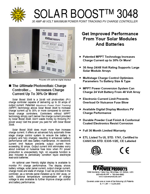
Pictured with optional digital displays!The Ultimate Photovoltaic Charge Controller... Increases Charge Current Up To 30% Or More!Solar Boost 3048 is a 24/48 volt photovoltaic (PV)charge controller capable of delivering up to 30 amps of output current. Patented Maximum Power Point Tracking (MPPT) technology allows Solar Boost 3048 to increase charge current up to 30% or more compared to conven-tional charge controllers. Controllers without MPPT technology simply can’t deliver the charge current provided by Solar Boost 3048. Don’t waste money by throwing PV power away! Get the power you paid for with Solar Boost 3048.Solar Boost 3048 does much more than increase charge current. It offers an advanced fully automatic three stage charge control system to ensure the battery is properly and fully charged, resulting in enhanced battery performance with less battery maintenance. An electronic current limit feature prevents output current from exceeding 30 amps. Output current limit eliminates worry about overload or nuisance fuse blow when PV power production is unexpectedly high. An equalize function is also included to periodically condition liquid electrolyte lead-acid batteries.An optional user friendly digital display is available to monitor PV charge performance. The display shows battery voltage, solar panel current, output charge current,charge mode and state of charge. It can be provided in the controller, as a remote panel installed up to 300’ away, or both. Optional temperature compensation of charge voltage is also available to further improve charge control and battery performance.1058 Monterey Vista Way, Encinitas, CA 92024, USA800-493-RVPP • Covered under one or more of the following US Patents6,111,391 •6,204,645SOLAR BOOST™ 304830 AMP 48 VOLT MAXIMUM POWER POINT TRACKING PV CHARGE CONTROLLERGet Improved Performance From Your Solar ModulesAnd Batteries•Patented MPPT Technology Increases Charge Current up to 30% Or More!•30 Amp 24/48 Volt Rating Supports Large Solar Module Arrays•Multistage Charge Control Optimizes Parameters To Battery Size & Type •MPPT Power Conversion System CanCharge 24 Volt Battery From 48 Volt Array •Electronic Current Limit Prevents Overload Or Nuisance Fuse Blow •Available Digital Display Monitors PV Charge Performance •Durable Powder Coat Finish & Conformal Coated Electronics Resist Corrosion •Full 36 Month Limited Warranty•ETL Listed To UL STD. 1741, Certified toCAN/CSA STD. E335-1/2E, CE Labeled!How Does Solar Boost 3048 Increase Charge Current?Solar Boost 3048 increases charge current by operating the PV module in a manner that allows the module to produce all the power it is capable of. A conventional charge controller simply connects the module to the battery when the battery is discharged. When the 75W module in this example is connected directly to a battery charging at 12 volts its power production is artificially limited to about 53 watts. This wastes a whopping 22 watts or nearly 30% of the available power!Typical 75W PV Module Performance25°C • 1000W/m2Solar Boost 3048’s patented MPPT technology operates in a very different fashion. Solar Boost 3048 calculates the module’s maximum power voltage, in this case 17 volts, and then operates the module at 17 volts to extract maximum power. The maximum power voltage is continually recalculated as operating conditions change. Module power, now 75 watts, feeds a high efficiency power converter which reduces the 17 volt input to battery voltage at the output. The full 75 watts delivered at 12 volts would produce 6.25 amps. An increase of 1.8 amps or 40% is achieved by converting the 22 watts that would have been wasted into useable charge current. This 12 volt example assumes 100% efficiency to illustrate the principal of operation. Actual boost will be somewhat less as some power is lost in wiring, fuses and in the Solar Boost 3048 controller.!How Much Increase Will You See?The actual charge current increase you will receive varies with module temperature and battery voltage. Lower module temperature increases available power, while lower battery voltage increases current for a given PV module power level. In comfortable temperatures current increase typically varies between 10 - 25%, with 30% or more easily achieved with a discharged battery and cooler temperatures. What you can be sure of is that Solar Boost 3048 will deliver the highest charge current possible for a given set of operating conditions. In conditions where extra power is not available, Solar Boost 3048 will operate as a conventional series pass controller with very low forward voltage drop.!Three Stage Charging Taken To The Next Level…Solar Boost 3048 uses the familiar three stage, Bulk, Acceptance, Float charge algorithm. But, controllers that determine full charge based on time or other factors not directly related to battery state of charge cannot realize all the benefits three stage charging has to offer.Solar Boost 3048 uses battery charge current matched to battery size in amp-hours to determine full charge. This method charges the battery quickly and completely without undercharge, overcharge or excessive water loss. When battery load is highly variable during charge, Solar Boost 3048 can further optimize charge control by using an external current shunt measuring net battery current. If desired, Solar Boost 3048 can also operate as a two stage charger.!SpecificationsOutput current rating...........................30ASystem voltage....................................24/48V nominalPV maximum open circuit voltage (140V)Voltmeter range/accuracy...................70.0V/±0.30% F.S. Current meter range/accuracy............50.0A/±0.50% F.S. Standby current...................................30mA typical Charge on current...24/48V...............100/70mA typical Acceptance voltage adjust range........26-32V/52-64V Float voltage adjust range...................0-4V/0-8V < Accp. Equalize voltage..................................2V/4V > Accp. Power conversion efficiency...............97% typical @ 25A Temperature comp. coefficient...........-5.0/-2.0mV/°C/cell Cabinet dimensions............................10”Hx8¾”Wx3½”D Remote display dimensions................4½”Hx4½”Wx1¾”D For additional product information, operators manuals, and technical bulletins, visit . !Part Numbers & Shipping Weight Solar Boost 3048 w/o display............SB3048L......8¾ lbs Solar Boost 3048 w/digital display....SB3048DL......9 lbs SB3048L front panel digital display...SB3048PDL.2¼ lbs Remote display, 25’ cable.................SB50RD25......2 lbs Battery Temp. sensor, 20’ cable.......930-0022-20...1 lbs Available From:As a part of our continuous improvement processspecifications are subject to change without prior notice© RV Power Products, Inc. 2001 • 440-0010 A1058 Monterey Vista Way, Encinitas, CA 92024, USA 800-493-RVPP • 760-944-8882 • 。
太阳能充放电控制器电路图文分析

太阳能充放电控制器电路图文分析太阳能控制器最主要功能是实现铅酸蓄电池的充放电保护。
下图是一12V蓄电池充放电保护电路的结构原理图。
系统主要由蓄电池充放电回路、充电比较电路、放电比较电路、充电控制电路、放电控制电路、稳压电路模块组成。
图3.21蓄电池充放电保护电路1. 蓄电池充放电回路蓄电池充放电回路由太阳能电池组件、保险丝、蓄电池及继电器组成。
如图3.29所示,当继电器J1加正向电压,则J1-1开关与蓄电池导通,实现12V蓄电池的充电。
如果继电器J1无正向电压,则J1-1开关与电阻R1及LED1导通,不给蓄电池充电,LED1指示灯点亮,表示不充电。
2. 充电比较器电路蓄电池充电比较电路由R2、PR1、比较器A1、R7、ZD1、R6组成。
该电路是一个正向迟滞比较电路。
其中比较器LM393采用单电源接线方式,输出U OH=8V(LM317稳压电路输出8V),U OL=0V;R7为反馈电阻;蓄电池电压变化信号通过R2电阻接入A1同相端;电阻R2及可调电阻RP1构成蓄电池电压采集电路;反相端链接到基准电路,电压为6.2V。
当蓄电池充电电压达到13.5V时,比较器A1的7号管脚输出高电平,通过充电控制电路关闭充电回路;当蓄电池不断的被使用,电压降低到13.1V时,比较器A1的7号管脚输出低电平,蓄电池充电电路被导通。
实现蓄电池过充保护功能。
3. 放电比较器电路蓄电池放电比较电路由R3、PR2、比较器A2、R8、ZD1、R6组成。
该电路也是一个正向迟滞比较电路。
R8为比较电路的反馈电阻;蓄电池电压变化信号通过R3电阻接入A2同相端;电阻R2及可调电阻RP1构成蓄电池电压采集电路;反相端链接到基准电路,电压为6.2V。
当蓄电池通过放电后,电压降低到10.8V时,比较器A2的1号管脚输出低电平,通过放电控制电路关闭放电回路(断开J2-1开关);当蓄电池电压上升到12.1V时,比较器A2的1号管脚输出高电平,通过放电控制电路导通放电回路(闭合J2-1开关),表示蓄电池可以放电。
- 1、下载文档前请自行甄别文档内容的完整性,平台不提供额外的编辑、内容补充、找答案等附加服务。
- 2、"仅部分预览"的文档,不可在线预览部分如存在完整性等问题,可反馈申请退款(可完整预览的文档不适用该条件!)。
- 3、如文档侵犯您的权益,请联系客服反馈,我们会尽快为您处理(人工客服工作时间:9:00-18:30)。
伏科太阳能充放电控制器
————————————————————————————————作者: ————————————————————————————————日期:
公司简介
作为一家德国独资企业,伏科集团是非并网电力系统太阳能产品部件全球最大供应商之一,从事设计、开发及制造各类型适合全球太阳能市场产品。
伏科致力于促进非并网电力系统的有效应用,提供高质量,高可靠性以及低成本的能源存储技术及系统部件。
伏科集团的分支机构遍布世界6大洲,其中包括3个生产基地和14个办事机构,建立了遍布全球范围的销售网络。
发展历史
伏科集团的历史可以追溯到20世纪80年代中期。
德国乌尔姆市应用科技大学的工程师们研究开发了太阳能充电控制器新技术,从而大大增强了非并网电力系统的整体效率。
从1991年开始,这种高端技术应用于太阳能充电控制器系列产品中。
2000年底,在德国乌尔姆应用科技大学和德国乌尔姆市及斯图加特市太阳能源及氢能源研究中心工程师们的努力下,成立了伏科集团。
自此,伏科集团集非并网电力系统太阳能产品部件研发、生产、销售于一身,快速发展壮大起来。
技术背景
伏科产品的研发重点在于解决独立供电系统的能量储存问题。
目标是通过优化能量的生产、存储和消耗实现系统高效率、高可靠性和低成本。
伏科集团拥有经验丰富的工程师和高素质的合作团队,并且与德国乌尔姆应用科技大学等研究机构有多年的技术交流与合作。
因此,伏科产品始终代表了先进的技术水平。
产品介绍
伏科为可再生能源非并网电力系统生产各种尖端科技部件。
提供优质产品的同时,也为客户提供必要的技术保障和支持。
伏科产品分为6大类:系统管理器,充放电控制器,直流节能灯,系统附件, 直流应用产品以及发电设备. 选择适合您的伏科产品,请参见应用案例.
技术品质
伏科致力于开发和生产严格符合高品质,高创新和高技术要求的产品。
我们优秀的研发队伍为达到这个目标,不断提高创新新技术,极大地提高了电池寿命,改善了太阳能系统的应用效率。
可靠性及成本
可靠性及成本是太阳能系统的关键考虑因素。
高科技含量先进技术的应用使伏科充电控制器等产品提高了蓄电池的可靠性,改善了系统的整体效率,并降低了能源储存的成本。
非并网系统中的特殊应用
伏科为可再生能源非并网电力系统提供各种尖端科技部件。
太阳能充电控制器、系统管理器、燃料电池及太阳能混合系统、微型水利发电机、直流灯及冰箱等产品可以广泛应用于非并网系统中,如工业电源、通讯、交通指挥、照明及游艇航行等休闲娱乐。
灵活性
高度的灵活性使我们能满足客户的特殊需要,可以为大型农村偏远地区供电工程提供专业的工业系统方案和低成本离网型系统解决方案。
充电控制器
此页面的控制器主要应用于系统容量为几百瓦的系统,如果你的系统达到几千瓦或者更大,请看我们的系统管理器
MPPT100/20
通过使用创新性的最大功率追踪技术,伏科公司的MPPT追踪器能保证太阳能阵列全天时、全天候的最大效率的工作。
CX系列
高效太阳能充电控制器系列
此款产品非常具有竞争力!设计并用于工业化系统并又有突出独特的特点比如:PC接口,内置一年的系统历史数据记录,用于路灯应用的路灯功能。
德国技术结合高质量的组件使这些产品能够工作在大约1000瓦的系统中。
还有负极接地车载应用的控制器!ﻫ
CML系列
太阳能充放电控制器/ 路灯控制器ﻫ世界畅销的太阳能充电控制器.无与伦比商业项目, 娱乐应用最好的性价比, 友好的客户界面.以及, 具有路灯功能用于路灯以及广告牌的应用.
CA系列
太阳能充放电控制器ﻫ采用客户方便造作的设计和技术, 伏科CA控制器对小型户用太阳能系统的蓄电池提供最好的保护。
满足系统低成本高可靠性的最佳选择。
CM系列
太阳能充电控制器ﻫCM控制器是一种小型的太阳能充电控制器,应用于不需要负载切断的场合, 负载和逆变器将直接连接到蓄电池上。
CA06,CA08,CA10, CA14
太阳能充放电控制器
两段式充电方式:强充,浮充
深度放电保护
串联PWM调节
内置温度补偿
通过MOSFET阻止蓄电池反向电流
全面电子保护:浪涌电压、极性反接,过载与短路等保护
三只LED指示灯:提供工作状态、充电状态、放电保护、故障显示
允许共正极接地
下载
产品简介(PDF 89KB)
产品说明书(多语言) (PDF1.8MB)
CE认证证书(PDF35KB)
附件
CMM
伏科公司第二代CA系列太阳能充放电控制器是专门为需要放电保护的小型太阳能系统而设计。
CA控制器的线路设计采用功率开关串联调节的模式,可以避免因为太阳能电池板处于短路状态而引起的单个太阳能电池片超温的问题。
端子部分采用了坚固的16平方毫米端子
以往用于保护蓄电池端的可熔性保险丝,现在已经由一个全面电子保护开关所替代,更加方便。
2个LED及1个双色LED显示充电进程、蓄电池的电压状态、负载切断显示和过载状态。
本产品通常应用于休闲及农村电气化系统。
CA系列控制器,可以满足系统低成本高可靠性的要求。
型号CA06 CA08 CA10 CA14
额定电压12V 12V 12V 12V
-3mV/cell*K温度补偿系数-3mV/cell*K -3mV/cell*K -3mV/cell
*K
额定充电电流5A 8A10A 14A
额定负载电流6A 8A10A 14A
尺寸80x 100x 32 mm
重量180gr
最大线径16mm2(AWG#6)
自消耗电流4mA
工作温度范围-40到+50 °C
防护等级IP22。