硫堇染色液(0.4%)
Intellian K4 K6 手册说明书

CONTENTSINTRODUCTION (1)I NTRODUCTION TO I NTELLIAN K4/K6 (1)F EATURES OF I NTELLIAN K4/K6 (2)B ASIC S YSTEM C ONFIGURATION (3)INSTALLATION (4)S YSTEM C OMPONENTS (4)T OOLS R EQUIRED FOR I NSTALLATION (7)P LANNING THE INSTALLATION (8)INSTALLING THE DACU (15)C ONNECTING THE SYSTEM TO A GPS (20)T ARGET S ATELLITE S ETTING (21)OPERATION INSTRUCTION (22)I NTRODUCTION (22)OPERATION USING THE DACU (23)DACU S OFT K EYS (23)N ORMAL M ODE (23)S ET U P M ODE (28)OPERATION USING PC CONTROLLER PROGRAM (51)I NTRODUCTION (51)I NSTALLATION USB TO S ERIAL D RIVER (52)P ROGRAM I NITIALING AND S ERIAL P ORT S ETUP (54)M AIN M ENU –U SING D EFAULT T RI S AT M ODE (55)S ET S ATELLITE I NFORMATION (56)C ONTROLLER MENU (59)TROUBLESHOOTING (64)PREPARATION FOR TRANSPORTATION (66)WARRANTY (67)APPENDIX: K6 TECHNICAL SPECIFICATION (68)APPENDIX: K4 TECHNICAL SPECIFICATION (69)INTRODUCTIONIntroduction to Intellian K4/K6Intellian K4/K6 is the world’s first marine in-motion satellite TV antenna system that is compatible with the Ka-band broadcasts from DIRECTV’s satellites, called 99˚W and 103˚W (the position related to Earth is expressed in longitude degrees). These satellites are now carrying the majority of DirecTV’s HD programming.This powerful and innovative design of the Intellian K4/K6 incorporates a plug-and-play system to control and support the Ku-band and Ka-band dual antenna system, which allows the users to enjoy both DIRECTV HD channels and standard channels at the same time. The Intellian automatic and fully-integrated dual antenna system offers users not only the simplest installation but also the most comfortable entertainment environment. As if at home, all a user needs to do is just switch the channel buttons on the TV remote control. Then, Intellian’s dual antenna system will automatically recognize where the selected channel is located between Ku and Ka-band and change the satellite if necessary.In addition, the Intellian K4/K6 19-inch rack-mount Dual Antenna Control Unit (DACU) allows for a hassle-free installation with its standard 8 receiver connector ports. This means that up to 8 receivers can be connected to the ACU from different locations on the vessel without additional multi-switches and wiring. Not to mention the Ku-band HD module and Multi-satellite Interface Module (MIM) are both embedded in the DACU which enables users to switch channels freely and simultaneously amongst DIRECTV’s 5 satellites; 2 for Ka-band (99˚W and 103˚W) and 3 for Ku-band (101˚W, 110˚W, and 119˚W) Features of Intellian K4/K6Full HD (High-Definition) Channel AvailabilityDIRECTV Ka-band signal reception for 99˚W and 103˚W satellites which are currently broadcasting more than 130 national HD channels.Dual Antenna SystemEnjoy watching channels from DIRECTV Ku-band satellites (101˚W, 110˚W, and 119˚W) and Ka-band satellites (99˚W and 103˚W) simultaneously just like a home system, using Intellian’s exclusive dual antenna system.Wide Range Search (WRS) AlgorithmSince the Ka-band signal has a very narrow beam width, the searching time can be extended if the antenna system is using the conventional searching method to search only the main lobe. Intellian’s patent-pending technology, WRS, can ultilize the side lobe of the Ka-band signal and jump onto the main lobe directly which will shorten the searching time significantly.Dynamic Beam Tilting (DBT) TechnologyAn advanced tracking technology is required for tracking the very narrow beam-width of the Ka-band signal. The DBT patent-pending technology allows the K4/K6 to have the most relibable and accurate tracking capability while the vessel is cruising at high speed or in rough sea conditions.New Rack-Mount Dual Antenna Control Unit (DACU)DACU controls dual antenna systems at one time, switches channels freely amongst DIRECTV’s 5 satellites using TV remote control and includes built-in HD and MIM modules. Easily connects up to 8 receivers directly from different rooms without any extra multi-switches and wiring to the DACU’s built-in 8 receiver connectors.NMEA 0183 GPS InterfaceA GPS Interface supports an external GPS which can provide the K4/K6even higher performance.K4/K6 (DTV 99W, 103W)Tapping Flat Head Sem’sFrontRearPower Drill Cross-HeadΦ10mm Drill Φ80mmPencil5mmAntenna Unit15°ObstacleAny obstacles located above a 15degree elevation can prevent theantenna from tracking the satelliteØ70cm (27.5”) Intellian K6Ø50cm (19.7”) Intellian K4WARNING Intellian K6 30.37cm (12”)Ø10mm Drillø80mm Hole sawWARNINGRF1 CableAntenna Unit11mm SpannerRF2 Cable Power CableDo not use excessive force when using the spanner, this will damage the WARNING26.58cm (10.5”) 13cm (5.1”)48.43cm (19”)46.5cm (18.3”)3.18cm (1.3”)(a) Table Mount Type(b) 19” Rack Mount Typeantenna. Refer the drawing below to connect cables.It will cause a critical malfunction if you do not follow the system diagram toCable(Black)Cable(White) K4/K6i4/i6B-Band ConverterWARNINGIntellian K4/K6•Connect the RF1 Cable (Yellow/15m) from the RF 1 connector on the antenna to the RF1 connector at Ka-band Antenna In section on the rear of DACU.•Connect the RF2 Cable (Green/15m) from the RF 2 connector on the antenna to the RF2 connector at Ka-band Antenna In section on the rear of DACU.•Connect the Power Cable (Red/15m) from the Power connector on the antenna to the Power/Data connector at Ka-band Antenna In section on the rear of DACU.Intellian i4/i6•Connect the RF1 Cable (Black/15m) from the RF 1 connector on the antenna to the RF1 connector at Ku-band Antenna In section on the rear of DACU. •Connect the RF2 Cable (White/15m) from the RF 2 connector on the antenna to the RF2 connector at Ku-band Antenna In section on the rear of DACU.Receivers•Connect the B-Band Converter (not supplied) to the RF connector on the rear of the receiver.• Connect the DACU-IRD Cable (3m) from the RF1 connector at To Receiver Section on the rear of the DACU to RF connector on the B-Band Converter. •Connect USB-cable (1.8m) from the USB1 connector at To Receiver Section on the rear of the DACU to the USB connector on the receiver.• Connect the AC power cable (1.5m) from AC power connector on the rear of DACU to a power source from 90~ 260 V AC.•Press the POWER ON switch on the rear of the DACU to start the operation of the antenna system automatically. Connecting the system to a GPSFor improved satellite tracking, you can connect your satellite TV system directly to your boat’s NMEA 0183 GPS system. To do this you will need lengths of cable suitable for connecting to your GPS system and the green 2-way DACU GPS connector supplied with your Intellian K4/K6 Satellite TV System.To connect the system to a GPS1. Strip back the insulation of each cable and connect a cable to eachterminal of the 2-way connector.2. Tighten the locking screws.3. Connect the cable from the +ve (positive)terminal of the DACUGPS connector to the NMEA OUT wire of the boat’s GPS system.4. Connect the cable from the –ve (negative) terminal of the DACUGPS connector to the ground wire of the boat’s GPS system.5. Refit the DACU GPS connector to the rear of the DACU.Ground (-)NMEA out (+)DTV119SAT A : DTV101 SAT B : DTV119 SAT A* : DTV101 SAT B* : DTV119SAVE ?YES NEXTSAT NAME : DTV101NEXTx2EDIT SAT INFO ?SAT NAME : DTV101INPUT +SAT NAME : DTV101 4. Set the satellite name.HOR LOW 12523 21096 HOR LOW NID 0x0003VER HIGH 12598 21096 VER HIGH NID 0x0003INPUT +VER LOW NID 0x0003HOR HIGH 12523 21096SAVE ?VERIFY : DVB DECODE VOLTAGE: DISEQC: ONLY 22KHZ PARAM: SCAN OFFYES NEXTx3SET ANT PARAMETER?WRS LEVEL : 0500SATNAME : DTV101SAVE ? 5. Input the WRS LEVEL.x4SET SAT PAIR ?x4x14. Input the longitude data.LONGITUDE ###.## ELONGITUDE ###.## EINPUT +SAVE ?SET SAT PAIR ?SAVE ?x5DO NOT USE DISEQCNEXT 4. Select the DiSEqC MethodSET SAT PAIR ?x6SF-601SSET SAT PAIR ?x7 ACU POWER : 27.1 VSET SAT PAIR ?x8 SET REMOCON ? FUNC : CHANGE SATPRESS A REMOTE KEY FUNC :NEXTx10 x9x11X12X13X142. Press “NEXT” or “YES” button to complete the installation.3. Execute the GUI Program in the same supplied CD-ROM to start the operation. (Refer to p.51)Tracking Satellite: DTV 99 ,DTV103Connects a PC with Ku (i4/i6) USB Interface:Tracking Satellite: DTV 101 ,DTV110, DTV119The operation method is exactly same for both K4/K6 and i4/i6. The below WARNINGSerial port settingConnect/Disconnect ButtonCommunication status displayBaudrate settingCommand Button• Baud Rate Setting – To display communication speed.• Connection Status Display – To display communication port betweenAntenna Status Monitoring• Search – Antenna is searching for the selected satellite. ◆ ♦•Satellite InformationThe name, longitude and confirmation method of the satellite isdisplayed when a satellite is selected in the list box. Push “EditSatellite Information” button to update the information on modifying the value.•DiSEqCCommand Button• Edit Satellite Information – To modify the satellite information. • Register for Sat A – To register a satellite to satellite A. • Register for Sat B – To register a satellite to satellite B. • Register for Sat C – To register a satellite to satellite C. • Not Use – Do not use DiSEqC.• Change Band – To use DiSEqC to change band.• Change Satellite – To use DiSEqC to change the satellite. • Singe Band – Antenna in use of Single LNB. • Universal Band – Antenna in use of universal LNB. • Set Local Frequency – To select local frequency of LNB.Load and Update Default Command Button1) Load Default: Click “load default” button to select *.rif file accordingto your region.2) Update Default: Click “Update default” button to open update default Dialogue. Click “yes” button to update the system.3) Click “confirm / yes” button to complete the update.Command Buttons• Load GPS Files – Reads in various city information from theGPS files.• Add City – Adds the name of city and its GPS information toGPS files•Delete City – Deletes the name of city and its GPS information Command Button• Edit Satellite Information – Toof the antenna•Satellite Information – Satellite information consists ofCommand Button•Edit Satellite Information – To change frequency information of the antenna. • Angle of AntennaTwo kinds of antenna movement is available. One is to move to the target position and the other is to move by certain amount of angle. The current position(angle) of the antenna is displayed as “Current” and to move to the target position, push “Go to target Position” button after keying in desired angle into “Target”. To move to a certain amount of angle only, move antenna to direction of up or down, and CW or CCW by using buttons after keying in the desired angle into the AZ and EL in the “Mover Step” box. Rotate LNB to direct theCommand ButtonsSet Control Parameter–To register parameters values.Set Flags–To set flag setting for WRS Method or Offset Difference.Product Information –Antenna dish size. Serial NO, Voltage for antenna and ACU,。
LED地砖屏视频处理器诺瓦科技K4系列用户使用说明教程大全

产品用户手册视频控制器K4S/K4声明欢迎您选用西安诺瓦电子科技有限公司(以下简称诺瓦科技)的产品,如果本文档为您了解和使用产品带来帮助和便利,我们深感欣慰。
我们在编写文档时力求精确可靠,随时可能对内容进行修改或变更,恕不另行通知。
如果您在使用中遇到任何问题,或者有好的建议,请按照文档提供的联系方式联系我们。
对您在使用中遇到的问题,我们会尽力给予支持,对您提出的建议,我们衷心感谢并会尽快评估采纳。
版权本文档版权归诺瓦科技所有,未经本公司书面许可,任何单位或个人不得以任何形式对文本内容进行复制、摘录等,违者必究。
商标是诺瓦科技的注册商标。
安全声明为避免可能的危险,请按规定使用此设备。
如出现损坏,非专业人士请勿擅自打开维修,请及时与本公司售后联系。
高压危险:本产品的工作电压为100~240V AC。
接地:本产品通过电源的地线与大地相连,请确保接地导体的良好接地。
电磁干扰:设备应远离磁铁、马达及变压器。
防潮:请将设备置于干燥、干净的环境中。
如有液体浸入,请立即拔掉电源插头。
远离易燃易爆危险物品。
禁止液体、金属碎片浸入机器内部,以免引起安全事故。
目录1型号说明1 2外观说明1前面板1后面板2 3信号连接3 4安装尺寸3 5操作动作说明4 6主界面4 7菜单操作5第一步输入设置5第二步快捷点屏6第三步亮度调节7第四步输出设置7拼接带载8高级设置9工厂复位14通讯设置14 8技术规格15 9常见问题16K4S/K4 用户手册⑧:扁口(A 型 USB 母口)是 USB 接口,连接 U 盘;方口(B 型 USB 母口 ) 是 USB 控制接口,连接 PC 通讯。
后面板DP DP 输入HDMI HDMI 输入CVBS1~CVBS3 3 路 PAL/NTSC 制式复合视频输入DVI-1~DVI-2 2 路 DVI 输入VGA1~VGA3 3 路 VGA 输入VGA OUT VGA 监视接口DVI OUT DVI 监视接口输出 1、2、3、4 4 路网口输出方口(B 型 USB 母口 )USB 控制(连接 PC 通讯,或 USB 级联输入)扁口(A 型 USB 母口)USB 级联输出注意:前面板和后面板的 A 型 USB 接口(扁口)禁止直接与控制计算机连接。
电镀通用配方大全(2)
电镀通用配方大全(2)氯化物镀镍液配方1组分 g/L 组分 g/L 氯化镍 200 硼酸 30-50 硫酸镍 1002PH值为2.5-4;温度为40-70?;电流密度为3-10A/dm。
配方2组分 g/L 组分 g/L 氯化镍 300 硼酸 30-402PH值为3.8;温度为55?;电流密度为1-13A/dm。
全硫酸盐镀镍液配方组分 g/L 组分 g/L 氯化镍 300 硼酸 402温度为46?;PH值为3.0-5.0;电流密度为2.5-10A/dm。
其他镀镍液配方1组分 g/L 组分 g/L 氯硼酸镍 300-450 硼酸 30-40 氟硼酸 5-40 2PH值为2.0-3.0;温度为40-80?;电流密度为2.5-20A/dm。
配方2组分 g/L 组分 g/L 氯硼酸镍 220 硼酸 30 氟硼酸 4-382PH值为2.0-3.5;温度为37-77?;电流密度为2.5-10A/dm。
配方3组分 g/L 组分 g/L 氨基磺酸镍 450 湿润剂 0.05 硼酸 302PH值为3.5-5.0;温度为38-60?;电流密度为2-16dm。
镀黑镍第一类镀黑镍配方1组分 g/L 组分 g/L 硫酸镍 70-100 硫氰酸铵 25-35 硫酸锌 40-45 硫酸镍铵40-60 硼酸 25-352阳极材料为镍板;PH值为4.5-5.5;温度为30-60?;电流密度为0.1-0.4A/dm。
配方2组分 g/L 组分 g/L 硫酸镍 60-75 硫氰酸铵 12.5-15 硫酸锌 30 硫酸镍铵35-452阳极材料为镍板;PH值为5.8-6.1;温度为25-35?;电流密度为0.05-0.15A/dm。
配方3组分 g/L 组分 g/L 硫酸镍 75 氯化铵 30 硫酸锌 30 硫氰酸钠 152阳极材料为镍板;PH值为5;温度为20-25?;电流密度为0.15A/dm。
第二类镀黑镍配方组分 g/L 组分 g/L硫酸镍 120-150 硼酸 20-252钼酸铵 30-40 PH值为4.5-5.5;温度为20-25?;电流密度为0.15-0.3A/dm。
柯达工业X射线胶片M100说明书
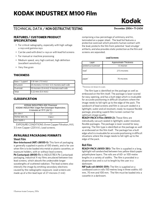
December 2006 • TI-2434TECHNICAL DATA / NON-DESTRUCTIVE TESTINGKODAK INDUSTREX M100 FilmFEATURES / CUSTOMER PRODUCT SPECIFICATIONS•For critical radiography, especially with high voltage x-rays and gamma rays •Can be used with direct x-rays or with lead foil screens •For manual or machine processing•Medium speed, very high contrast, high definition (excellent sensitivity)•Very fine grainTHICKNESSCLASSIFICATIONEXPOSURE CONDITIONS: 8 mm Copper Filtration, HVL 3.5 mm Copper (220 kV), Lead screens.AVAILABLE PACKAGING FORMATSSheet FilmNon-Interleaved (NIF) (M100-1): This form of packaging is generally supplied in packs of 100 sheets, and is for use when film is to be loaded into metal or plastic cassettes, or exposure holders, with or without lead screens.Pb Contactpak (M100-7): In INDUSTREX Pb Contactpak packaging, industrial X-ray films are placed between two lead screens, which absorb the undesirable longerwavelengths of scattered radiation. The lead screens also intensify the image by emitting secondary electrons caused by the radiographic exposure. Lead screens are made up of a thin lead layer of 27-microns (1-mil)Base / Support 0.18 mm (7.0 mils)Emulsion 25 microns (1.0 mil); 12.5 microns each side Overcoat 10 microns (0.4 mil); 5 microns each side T otal0.22 mm (8.4 mils)KODAK INDUSTREX 43IC ProcessorKODAK INDUSTREX Single Part Developer Replenisher,8 minutes at 79°F (26°C)EN-584-1C2ASTM 1815-96Class I ISO 11699-1T1comprising a low percentage of antimony and tin,laminated on a paper sheet. The lead foil features a protective overcoat which prevents human contact with the lead, protects the film from potential "lead smudge" artifacts, and also provides static protection as the film and screens are separated.Lead Screens*Thickness not drawn to scale.The film type is identified on the package as well as embossed on the film itself. The package is laser-scored for easy opening, and has a butt edge which is invaluable for accurate positioning in difficult situations where the image needs to fall right up to the edge of the pack. The sandwich of lead screens and film is vacuum sealed in a lighttight, water and oil resistant, ready-to-expose flexible package, providing superb film/screen contact for optimum image quality.READY-PACK II Film (M100-2): These films areindividually vacuum sealed in lighttight, water-resistant, flexible packages. The package is laser-scored for easy opening. The film type is identified on the package as well as embossed on the film itself. The package has a butt edge which is invaluable for accurate positioning in difficult situations where the image needs to fall right up to the edge of the pack.Roll FilmREADY-PACK (M100-381): The film is supplied in a long, lighttight roll sandwiched between two yellow-black paper polyethylene layers. The rolls are of 60- or 100-metre lengths in a variety of widths. The film is provided in a dispenser box and is cut to length by the user in a darkroom.NIF bulk roll (M100-359): The film is supplied on acardboard core in rolls 150 metres long in three widths: 60 mm, 70 mm and 100 mm. The film must be loaded into a cassette in a darkroom.LayerApproximate Thicknessprotective overcoat1.5 micron lead *27.5 micronspaper *70 micronsSAFELIGHT RECOMMENDATIONSUse a KODAK LED Safelight (660 nm red) or a red safelight filter (i.e. KODAK 1, 1A, or 2 Safelight Filter) in a suitable safelight lamp equipped with a 15-watt bulb. Keep the film at least 4 feet (1.2 metres) from the safelight.Note: Other safelight filters (i.e. KODAK 8 and GBX-2 Safelight Filter) which block radiation at 550nm and shorter wavelengths are also suitable for use.STORAGE AND HANDLINGHandle film carefully to avoid physical strains such as pressure, creasing, or buckling.It is important to realize that meeting the chemical and physical requirements does not by itself ensure thatrecords will not deteriorate. It is essential to provide proper storage conditions. ASTM E 1254 gives details of storage conditions. ISO 18911 and ISO 18902 give, for processed films, recommended storage conditions and specifications for the respective enclosure materials.Unexposed50 to 70°F (10 to 21°C), 30 to 50% RH. Properly shield from x-rays, gamma rays, or other penetrating radiation.ExposedKeep cool, dry, and properly shielded from penetrating radiation. Process as soon as possible after exposure.Processed60 to 80°F (15 to 27°C), 30 to 50% RH.RELATIVE EXPOSUREKODAK INDUSTREX Films for Various Processing ConditionsEXPOSURE CONDITIONS: 8 mm Copper Filtration, HVL 3.5 mm Copper (220 kV), Lead screens* M100 Film in 8 min 79°F (26°C) cycle is assigned a relative exposure of 1.KODAKINDUSTREX FilmsKODAK INDUSTREX Processor KODAK INDUSTREX Chemicals8 min 79°F (26°C)DR50 1.6M100* 1.0MX1250.6T2000.4AA 4000.3HS8000.15RELATIVE EXPOSURE FOR VARIOUS ENERGY LEVELSFor each exposure condition, M100 Film is assigned a relative exposure of 1.00.KODAK INDUSTREX Processor, 8 minute 79°F (26°C) cycle.* In accordance with ISO 7004 standard. Without lead screens † In accordance with ISO 7004 standard - EN 584-1 Lead screens ‡ 8 mm Copper filtration. 100/200 microns lead screens § 100/200 microns lead screensAUTOMATIC PROCESSINGNotice: Observe precautionary information on product labels and on the Material Safety Data Sheets.See Kodak publication TI-2621, Processing KODAKINDUSTREX Films , for additional information on automatic processing.EXPOSURE CONDITIONS: 200/220 kV, ISO/ANSI/EN Conditions, KODAK INDUSTREX ChemicalsFilm Characteristics (Sensitometric)* Contrast calculated between net densities of 1.5 and 3.5.Recommended Replenishment RatesThe consistency of the radiographic quality is related to the accurate adjustment of the replenishment rate.Replenishment should maintain the chemical equilibrium, replacing the components used by the film.* For optimum archivability, a 10% increase in fixer replenishment rate may bedesirable.INDUSTREXFilms ISO 120kV *EN 220kV †Iridium ‡Cobalt §DR50 2.3 1.6 1.6 1.6M100 1.0 1.0 1.0 1.0MX1250.70.60.60.6T2000.40.40.40.3AA4000.30.30.20.2HS800—0.15——KODAK INDUSTREX Processor / Cycle Base + Fog Contrast *M43IC, 8 min 79°F (26°C)0.19 5.4M43IC, 5 min 86°F (30°C)0.19 5.25M35, 10.5 min 86°F (30°C)0.194.8Solution Replenishment Volumeper 35 x 43 cm (14 x 17 inch) sheetper m 2Developer 100 mL 665 mL Fixer180 mL *1200 mLWashing and DryingWashing: Follow the processor manufacturer'srecommendation for wash flow rate, or adjust flow to achieve the equivalent of the wash tank capacity every five minutes, or twelve tank volumes per hour. Insufficient wash flow can adversely affect the life expectancy of processed radiographs. Wash flow rate should be increased if chemical spot tests or other analyticalmethods reveal a high level of retained chemicals in the processed film. For best results, the wash tank should be drained daily and left empty when not in use.Drying: Follow the processor manufacturer'srecommendation for dryer settings. In general, the dryer should be set to a temperature slightly above (3°C/5°F) the lowest temperature required to eliminate any signs of tackiness in films exiting the dryer.MANUAL PROCESSINGNotice: Observe precautionary information on product labels and on the Material Safety Data Sheets.See Kodak publication TI-2643, Guide to Manual Processing of NDT Films , for additional information on manual processing.Film Characteristics (Sensitometric)* Contrast calculated between net densities of 1.5 and 3.5.Development ConditionsBase + Fog Contrast *5 min 68° (20°C)0.19 5.03 min 75° (24°C)0.195.3DevelopmentDevelop with rack and tank, using properly replenished solutions.•Remove film and hanger 5 seconds before end of development. DO NOT ALLOW EXCESS DEVELOPER TO DRAIN BACK INTO THE TANK. Normally this will carry out the proper amount of solution to permit correct replenishment.•Use floating covers on developer tanks to reduce oxidation and evaporation; store developer replenisher in a closed container. •Fill the developer and fixer tank to its original level each morning with developer or fixer replenisher solution (topping off).•Discard solution after adding two tank volumes of replenisher to tank, or at least once a month, and refill with fresh solution.Stop, Fix, Wash and Dry StepsStop baths check development, prevent most spots or streaks, and prolong the life of the fixing bath.Immerse the film in fixer for 3 to 6 minutes , agitating for 5 seconds every 30 seconds . Film should remain in fixer for twice the time it takes to "clear" it (when the milky look disappears). Never fix film for less than 3 minutes.KODAK Hypo Clearing Agent may be used following the fixer to reduce washing time and conserve water. First rinse films in running water for 30 seconds, the use Hypo Clearing Agent for 1 to 2 minutes, followed by a final running water wash for 5 minutes.T emperature RecommendedT ime(Minutes)Agitation KODAK INDUSTREX Single Part Developer Replenisher68°F (20°C)72°F (22°C)75°F (24°C)79°F (26°C)5432Intermittent (5 seconds every 30 seconds)T emperatureRecommendedT ime Agitation KODAK Indicator Stop Bath, or acetic acid (diluted to 3.5%) solution 60 to 85°F 16 to 30°C30 to 60 secondsContinuous, ModerateKODAK Rapid Fixer, KODAK INDUSTREX Manual Fixer, or KODAKINDUSTREX LO Fixer and Replenisher 60 to 85°F 16 to 30°C3 to 6 minutes, or twice the clearing timeVigorous for 15 seconds, then intermittent (5 sec every 30 sec)Running water wash(8 volumechanges per hour)60 to 85°F 16 to 30°C 10 to 30MinutesKODAK INDUSTREX M100 FilmAerial and Industrial MarketsEASTMAN KODAK COMPANY • ROCHESTER, NY 14650-0505Revised 12-06Printed in U.S.A.KODAK INDUSTREX M100 Film KODAK Publication No. TI-2434NOTICE: While the sensitometric data in this publication are typical of production coatings, they do notrepresent standards which must be met by Kodak. Varying storage, exposure, and processing conditions will affect results. The company reserves the right to change and improve product characteristics at any time.To minimize water spots and drying marks, use KODAK PHOTO-FLO Solution after washing.Dry in a dust-free area at room temperature or in a suitable drying cabinet. Temperature not to exceed 120°F (50°C).Recommended Replenishment RatesMaintain chemical activity and solution level in the developer tank by adding 100 mL (3.38 fluid ounces) of replenisher according to instructions for each 14 x 17-inch (35 x 43 cm) film processed. Stir vigorously after each addition. Replenish the fixer tank at the rate of 180 mL (6 fluid ounces) per 35 x 43 cm (14 x 17 in) sheet of film processed.CURVESCharacteristic Curves, Manual ProcessingCharacteristic Curves, Machine ProcessingKodak, Industrex, Ready-Pack, and Photo-flo are trademarks.。
2800系列使用手册

UV-2802S
0.5、1、2、4nm
≤0.15%T 在 220nm,340 nm 处 0-200%T,-0.3-2.80A, 0-9999C(0-9999F) ±0.5%T RS-232C 串口,Centronics 并口配 Hp,Epson 兼容激光,喷墨打印机 550×400×270 580×400×280 16kg 约 21kg
23仪器外观uv2800见图21图22样品室盖键盘液晶显示屏拉杆图21散热风扇电源插座打印口液晶对比度调节旋钮电源开关110v220v转换开关rs232串行通uv28022802s见图23图24图25液晶对比度调节旋钮液晶显示屏样品室盖拉杆键盘图23电源指示灯打印口电源开关rs232串行通讯口图24电源插座散热风扇散热孔110v220v转换开关换灯口盖板观察孔图2524仪器安装将仪器放置于水平平台上仪器应避免阳光直射远离电磁发射装置和大功率电气装置使用环境不能有尘埃腐蚀性气体和振动
UV-2800/2802/2802S 型
紫外可见分光光度计 用户使用手册
尤尼柯(上海)仪器有限公司
目 录 第一章 概述………………………………………………………………………………… 1. 1 原理……………………………………………………………………………………… 1. 2 用途……………………………………………………………………………………… 1. 3 特点……………………………………………………………………………………… 第二章 主要技术指标……………………………………………………………………… 2. 1 技术指标………………………………………………………………………………… 2. 2 随机附件………………………………………………………………………………… 2. 3 仪器外观………………………………………………………………………………… 2. 4 仪器安装………………………………………………………………………………… 第三章 仪器的基本操作…………………………………………………………………… 3. 1 显示屏和按键…………………………………………………………………………… 3. 2 仪器上电………………………………………………………………………………… 3. 3 仪器的基本操作………………………………………………………………………… 3. 3. 1 调空白………………………………………………………………………………… 3. 3. 2 设置波长……………………………………………………………………………… 3. 3. 3 调出, 存储, 打印实验结果………………………………………………………… 3. 4 试验前的准备…………………………………………………………………………… 第四章 光度计模式………………………………………………………………………… 4. 1 测试方法描述…………………………………………………………………………… 4. 1. 1 吸光度模式…………………………………………………………………………… 4. 1. 2 透过率模式…………………………………………………………………………… 4. 1. 3 含量 (浓度) 模式……………………………………………………………………… 4. 2 打印实验报告…………………………………………………………………………… 第五章 定量测量…………………………………………………………………………… 5. 1 测量方法描述…………………………………………………………………………… 5. 1. 1 选择浓度单位………………………………………………………………………… 5. 1. 2 选择校正方法………………………………………………………………………… 5. 1. 3 选择曲线拟合方法…………………………………………………………………… 5. 1. 4 直接输入标准曲线…………………………………………………………………… 5. 1. 5 建立标准曲线………………………………………………………………………… 5. 1. 6 定量测量……………………………………………………………………………… 第六章 光谱扫描…………………………………………………………………………… 6. 1 参数设置………………………………………………………………………………… 6. 2 扫描模式选择…………………………………………………………………………… 6. 3 建立基线………………………………………………………………………………… 6. 4 扫描样品………………………………………………………………………………… 6. 5 图谱处理………………………………………………………………………………… 6. 5. 1 改变标尺……………………………………………………………………………… 6. 5. 2 峰谷查寻……………………………………………………………………………… 6. 5. 3 存储, 调入, 打印扫描曲线………………………………………………………… 第七章 动力学测量………………………………………………………………………… 7. 1 参数设置………………………………………………………………………………… 1 1 1 1 2 2 2 3 5 5 5 6 8 8 9 10 12 12 12 13 13 13 15 15 15 15 16 16 16 17 19 21 21 21 22 22 23 23 23 24 26 26
TORK-LOK 拧紧锁筒和椅子系列说明书

Precision Mated Flats on Both Expander and Arbor BodyPrecision Mated Flats on ColletSafety Stops Contraction ExpansionTork-Lok Arbors and ColletsTORK-LOK ARBORS AND COLLETSThe Tork-Lok arbor design answers the need for a completely versatile workholding device. Precision ground flats on collets and arbors improve long-term accuracy and torque transmission. Standardization of components permits interchangeability and combination possibilities. Locates straight or tapered holes on true center.INSTALLATION AND OPERATING INSTRUCTIONSSafety StopsThe expansion safety stop is fixed in all styles and requires no adjustment. The contraction or loading position safety stop is adjusted to suit the part being chucked.PreloadAll collets are manufactured to include a preload. Collets should not be adjusted below the range minimum for that collet. Preloads are .008 average on sizes from .500-.874 and .015 from .875-4.467.Special Work Stop ConsiderationCombination Work Stop and Retaining Sleeve: Restrictor Type Work Stops are necessary for parts whose gripping length is shorter than the collet. Since the Tork-Lok collet expands at both ends, a retaining sleeve is needed to prevent the free end of the collet from over expanding; a Restrictor Expander is used to reduce the expansion safety stop, preventing collet breakage (in case arbor is operated without a part in position).NOTES:• All Tork-Lok arbor applications require a part stop• If Restrictor Type Stop is used, a special Restrictor Expander is required • Contact us at 1-800-228-BUCK for more informationDRAWBAR MODELDrawbar should be in forward or push position. Adjust forwardexpander with Allen wrench until part is a slip fit on the collet. Collet flats both ends must mate.Collet ChangingDrawbar should be in forward positions. Using Allen wrench, remove forward expander. Collet and rubber sleeve can then be removed. Wash parts in clean solvent. Lightly grease expander flats in contact. Install forward expander. Adjust according to instructions outlined above.AIR-OPERATED MODELAir pressure on the cylinder should be at 70 psi. Adjust forward expander with Allen wrench until part is slip fit on the collet. Collet flats on both ends must mate.Collet ChangingWith air pressure at 70 psi, follow instructions listed in Drawbar Model.To Interchange AssembliesApply 70 psi, remove mounting screws, turn arbor assembly counterclockwise until drawbar disengages from piston assembly.To mount assembly, apply 70 psi. Be sure threads on drawbar are clean and oiled. Turn arbor assembly clockwise until face contacts cylinder. Back off to align tapped holes in cylinder. Insert screws and adjust according to instructions outlined above.Expansion StopForward ExpanderDirt Seal Contraction StopDrawbar ConnectorForward ExpanderExpansion StopContraction StopNote: Max. Drawbar pullstamped hereDirt SealChip ClearanceMachine ID of sleeve to high limit of part +.02 - +.004AIR-OPERATED MODELDRAWBAR MODELTYPICAL APPLICATIONS FOR ARBORSPISTON DIFF. CARRIER TRACK ROTOR BALL JOINT GEAR BLANK PUMP HOUSINGCOMPRESSION PLATEFRONT BRAKE DRUMSpecial arbor combinations are available upon request. Please contact us at 1-800-228-BUCK for more information.Arbor Applications36Tork-Lok Drawbar ModelsLong Series ArborsFEATURES AND BENEFITS:• Answers your need for versatility• Precision-ground flats improve accuracy• Standardization permits interchangeability• Locates straight or tapered holes on true center• Requires a part stopSHIPS COMPLETE WITH:• Flange body• Connector• Expander•Collet sold separately; see pages 40 & 41FEATURES AND BENEFITS:• Bolt circle has versatile three-bolt pattern • Tighter tolerance on size and parallelism for locator mounting• Provisions for air sensing• Precision-ground flats improve accuracy • Standardization permits interchangeability• Locates straight or tapered holes on true center • Requires a part stopTork-Lok Metric Drawbar ModelsLong Series ArborsDimensions denoted in millimeters unless otherwise specified.SHIPS COMPLETE WITH:• Flange body • Connector • Expander• Collet sold separately; see pages 40 & 41- Optional assembly method with male thread38SHIPS COMPLETE WITH:• Flange body • Connector • Expander• Collet sold separately; see pages 40 & 41FEATURES AND BENEFITS:• Answers your need for versatility• Precision-ground flats improve accuracy • Standardization permits interchangeability• Locates straight or tapered holes on true center • Requires a part stopTork-Lok Drawbar ModelsShort Series Arbors1-800-228-BUCK 39Tork-Lok Metric Drawbar ModelsShort Series ArborsFEATURES AND BENEFITS:• Bolt circle has versatile three-bolt pattern • Tighter tolerance on size and parallelism for locator mounting• Provisions for air sensing• Precision-ground flats improve accuracy • Standardization permits interchangeability• Locates straight or tapered holes on true center • Requires a part stopSHIPS COMPLETE WITH:• Flange body • Connector • Expander• Collet sold separately; see pages 40 & 41- Optional assembly method with male threadT o r k -L o k L o n g S e r i e s C o l l e tsF E A T U R E S A N D B E N E F I T S :• P r e c i s i o n g r o u n d fla t s • C o l l e t s i n t e r c h a n g e a b l e o n a l l a r b o r s w i t h i n s p e c i fie d r a n g e • A c c u r a c y o f a r b o r n o t a f f e c t e d b y i n d e x i n g o f c o l l e t s h a f t • H i g h -g r a d e s t e e l s , p r e c i s e l y h e a t t r e a t e d • S i l i c o n e s e a l i n g o f c o l l e t s l o t s f o r s p e c i a l j o b s i s a v a i l a b l e o n r e q u e s t f o r a d d i t i o n a l c h a r g e • C o l l e t s i n o v e r s i z e (o v e r l a p ) r a n g e s a r e a v a i l a b l e – s e e b o l d r a n g esO v e r s i z e c o l l e t s A C 107-110;209-212 a n d 311-318 s h o u l d b e u s e d o n l y i n l i g h t t u r n i n g o r g r i n d i n g o p e r a t i o n s .T o r k -L o k S h o r t S e r i e s C o l l e tsF E A T U R E S A N D B E N E F I T S :• P r e c i s i o n g r o u n d fla t s • C o l l e t s i n t e r c h a n g e a b l e o n a l l a r b o r s w i t h i n s p e c i fie d r a n g e • A c c u r a c y o f a r b o r n o t a f f e c t e d b y i n d e x i n g o f c o l l e t s h a f t • H i g h -g r a d e s t e e l s , p r e c i s e l y h e a t t r e a t e d • S i l i c o n e s e a l i n g o f c o l l e t s l o t s f o r s p e c i a l j o b s i s a v a i l a b l e o n r e q u e s t f o r a d d i t i o n a l c h a r g e • C o l l e t s i n o v e r s i z e (o v e r l a p ) r a n g e s a r e a v a i l a b l e – s e e b o l d r a n g esO v e r s i z e c o l l e t s A C 7110-7115; 7213-7220 a n d 7317-7328 s h o u l d b e u s e d o n l y i n l i g h t t u r n i n g o r g r i n d i n g o p e r a t i o n s .4142Tork-Lok Replacement ComponentsSold in KitsAir-Operated ModelsMeasurements in inches.1-800-228-BUCK 43Manual Tork-Lok FixturesOPERATING INSTRUCTIONS1. Mount fixture on machine.2. Adjust expander with Allen wrench so that part is a slip fit on collet. Be sure collet and arbor flats mate on both ends.3. To clamp part, move handle clockwise.4. To release part, move handle counterclockwise.ORDERING INSTRUCTIONSA complete fixture is ready to mount on your machine. When ordering additional arbor assemblies for fixture use, indicate connector also. When ordering base assemblies, indicate connector(s) desired.TO CHANGE ARBOR ASSEMBLIESFrom one size range to another (see chart above for arbor assembly and connector):1. Remove cap screws and turn arbor assembly off the base clockwise.2. CAUTION Handle must be in unlocked position.3. Turn replacement arbor assembly counterclockwise into base until snug. Continue movement until holes line up. Replace cap screws.ADAPTATION OF DRAWBAR MODELS1. Procure proper fixture base and connectors to accommodate drawbar model you have (see chart above).2. Remove drawbar connector (A) by backing out expander (B) with Allen wrench until connector is free. Remove retaining ring.3. Insert fixture connector (C or D) by turning in expander (B) until flats mate and are firm on both ends. No retainer ring is necessary.4. CAUTION Handle must be in unlocked position.5. Turn assembly counterclockwise into base assembly until snug. Continue movement until holes line up. Replace cap screws.Installation and Operating InstructionsTORK-LOK FIXTUREThe Tork-Lok Fixture is a powerful locking mechanism for use with Tork-Lok Arbors. It features low initial cost and little maintenance for milling and drilling operations.onArbor AssemblyBase Assembly Locked PositionUnlocked PositionOUR BRANDSFORKARDT MAIN OFFICE 2155 Traversefi eld Dr Traverse City, MI 49686Tel: (+1) 800-544-3823Fax: (+1) 231-995-8361E-Mail:*****************FORKARDT CHINABuilding, No.209, Taigu Road Shanghai Waigaoqiao F .T.Z.200131 P .R.CTel: 86-021-********E-mail:****************.comFORKARDT DEUTSCHLAND GMBH Heinrich-Hertz-Str. 7D-40699 ErkrathTel: (+49) 211-25 06-0Fax: (+49) 211-25 06-221E-Mail:*****************FORKARDT FRANCE S.A.R.L.28 Avenue de BobignyF-93135 Noisy le Sec Cédex Tel: (+33) 1-4183 1240Fax: (+33) 1-4840 4759E-Mail:****************************FORKARDT INDIA L.L.P .P No. 39, No. 5-5-35/187Ayyanna Ind Park IE Prashant Nagar Kukatpally, Hyderabad, AP . 500072Tel: 040-40020571Fax: 040-40020576E-mail:**********************。
Klockner Moeller S40软件 Sucos4程序导入 使用说明书

Application Note - Klockner Moeller S40 softwareKlockner MoellerImport of Sucos4 programs into S40 software.ContentsManual (1)Open project (1)Import program (1)Syntax check (1)Generate system parameters (2)Topology Configuration (2)Printing sections of program (2)Program transfer (2)Program monitoring (2)In order to import an older program, from the DOS based Sucos4 software, into S40 software you will need various files for the program to be imported. These files all have the project name with file extensions .Q42, .K42, .Z42 but you should have all of the files specified in the INCLUDE statements.ManualRefer to the User Interface Sucosoft S40 Programming Software manual page 69 onwards for details of what can and cannot be converted.Open projectOpen the S40 software then select the Project Manager, select Project > New and use Select Directory to navigate to the directory where the program files are. In the Project Path box add the new project name onto the end of the directory path you have just navigated to. Select OK and you should see the project tree with the name you just entered. Minimise this window.Import programSelect the POU Editor then select File > Import. Select File > Open then click on the appropriate .Q42 file and press OK. Now click on the matching .Z42 file and press OK. The program should import with the IL Editor on the right and the Syntax Controlled Variable Editor on the left.Syntax checkSelect File > Syntax Check and then save the POU when requested, the system should respond with POU compiled error free. If there are errors these need to be corrected at this stage.*********************.ukApplication Note - Klockner Moeller S40 softwareGenerate system parametersOpen the Code Generation module and select Generate > New Make List, the system should offer files names of the project name with .poe and .dcf extensions. Select OK to generate the new MAKE file.Select Options > Configure PLC and enter the appropriate system parameters, then select the Compiler tab and enter the active and retentive marker range. If you do not know these values then return to the POU Editor, the values are shown as comments at the top of the IL Editor. If the program is not shown in the IL Editor then select File > Open and open it.Select Generate > Generate All to produce a program file for the PLC. The program will hopefully compile OK, possibly with warnings.Topology ConfigurationThere is no import facility for this function, open the Topology Configurator, create the right layout and save it as the .dcf file. Click on the PLC and select Edit > Set Parameters for PLC parameters or select Edit > Remote Expansion to add I/O modules.Printing sections of programOpen the appropriate POU in the POU Editor. Select File > Print and then select GBFORM1.WMF as the template, select Additional Settings and then with only Instruction Section checked open the Settings box for Instruction Section. Enter the lines that you want printed and press OK, close the Additional Settings window with OK and then select Print. Note that irrespective of what lines numbers are asked for the Global Variable list is always printed first. Program transferThis section may be slightly incorrect as no PLC was connected at the time so some menus could not be accessed. Select the Test & Commissioning module, double click on the Device Type and select the appropriate PLC, double click on the Interface and select the correct COM Port number then click Connect, the Status should show Connected. Select Device > Transfer/File Manager and then highlight the required .pcd file, press execute to transfer to the PLC as long as ‘Transfer to PLC’ is showing in the Action box.Program monitoringIn the Test & Commissioning module select Device > Program to open the resource window, expand the Resource tree in the left hand pane and highlight the require POU (there is probably only one POU). Press Display/Change POU to open the monitoring window.Tony SpearingOctober 2011。
Yaskawa Motoman 机械臂控制器用户指南说明书

Step 30. Select the Deviation Control Type Submenu Press d . If flashing _DEV Deviation is displayed press a ,otherwise press b until flashing _DEV is shown. Now press d to store and go to next menu item.Step 31. Select the Latched Type SubmenuPress d . If flashing UNLT Unlatched is displayed press a ,otherwise press b until UNLT is displayed.Press d to store and advance to next menu item.Step 32. Select the Normally Open Type of Contact Closure SubmenuPress d . If flashing N.o.Normally Open is displayed,press a , otherwise press b until N.o.is displayed. Press d to store and advance to next menu item.Step 33. Select the Above Type of Active Submenu Press d . If flashing ABoV Above is displayed, press a ,otherwise press b until ABoV is displayed. Press d to store and advance to next menu item.Step 34. Enable Alarm 1 at Power On (A.P.oN )Press d . If flashing ENBL is displayed, press a , otherwise press b until ENBL is displayed. Press d to store and advance to next menu item.Step 35. Enter Alarm 1 High SubmenuPress a twice to skip ALR.L Alarm 1 Low value. ALR.L is for below & ALR.H for above.Step 36. Set the Alarm 1 High value (ALR.H )Press d . Press b or c until value to set the display to 002.0. Press d to save.Step 37. Enter the Alarm 2 MenuThe display will show ALR2the top menu for Alarm 2.Repeat steps from 28 to 36 to set for Alarm 2 the same conditions as for Alarm 1.Step 38. Skip the Loop Break Time Menu (LOOP )Press a to go to the OUT1Output 1 Menu item.Step 39. Configuration the Output 1 MenuSet Alarm 1 Disabled (Step 29) to be able to Enable Output 1.Configure Out 1 as CTRL / PID , ACTN / RVRS , AUTO /DSBL , ANTL / ENBL , PRoP / 005.0, REST / 0180, RATE /018.0, CYCL / 0010and DPNG / 0003. Please refer to the operator’s manual if needed. Press d to save and go to the next menu item.Step 40. Configuration of Display Color Selection Press a until the COLR Display Color Selection Menu appears on the Display. Configure COLR as N.CLR /GRN (green), 1.CLR / RED (red), 2.CLR /AMBR (amber). Please refer to the operator’s manual if needed.For color change on Setpoints refer to Owners Manual Section 2.Step 41. Run a TestPress a until reset the controller and return to RUN Mode to display 075.0(Ambient Temperature). Now you are ready to observe temperature as it rises 10°F higher thandisplayed. Touch the tip of the Thermocouple to raise the temperature above the Alarm 2 High value 082.0, and AL2will turn on, and Display Color will change from Green to Amber. Continue touching the tip to raise the temperature above the Alarm 1 High value 087.0and Display Color will change from Amber to Red. Annunciator “1” is turning on and off displaying output 1.Step 11. Enter to the Thermocouple Type Input Submenu Press d to display flashing, previously selected Thermocouple type.Step 12. Scroll through available selection of TC types Press b to sequence thru flashing Thermocouple types,(select k -for type "K" CHROMEGA ®/ALOMEGA ®)J K T E N DIN J R S B C - TC types J k t E N dN J R S b C - DisplayStep 13. Store TC typeAfter you have selected the Thermocouple type press d to store your selection, the instrument automatically advances to the next menu item.Step 14. Enter to Reading Configuration MenuThe display shows RDG Reading Configuration, which is the top menu for 4 submenus: Decimal Point, Degree Units,Filter Constant and Input/Reading Submenus.Step 15. Enter to Decimal Point Submenu Press d to show DEC Decimal Point.Step 16. Display the Decimal Point positionPress d again to display the flashing Decimal Point position.Step 17. Select the Decimal Point position Press b to select FFF.F Decimal Point position.Step 18. Store selected Decimal Point positionBy pressing d momentarily the Decimal Point position will be stored and the instrument will go to the next menu item.Step 19. Enter to Temperature Unit Submenu Display shows TEMP Temperature Unit.Step 20. Display available Temperature Units Press d to display the flashing Degree °F or °C .Step 21. Scroll through Temperature Units selection Press b to select °F Degree.Step 22. Store the Temperature UnitPress d to display momentarily that the Degree Unit has been stored and the instrument will go automatically to the next menu item.Step 23. Enter the Filter Constant Submenu Display shows FLTR Filter Constant Submenu.Step 24. Display the Filter Constant Value Submenu Press d to display the flashing, previously selected Filter Constant.Step 25. Scroll through available Filter Constants Press b to sequence thru Filter Constants 0001, 0002,0004, 0008, 0016, 0032, 0064and 0128.Step 26. Store the Filter ConstantPress d momentarily to store 0004Filter Constant and the instrument will automatically go to the next menu item.Step 27. Enter Alarm 1 MenuThe display will show ALR1the top menu for Alarm 1. In the following steps we are going to enable Alarm 1, Deviation,Unlatch, Normally Open, Active Above, Enable at power on and +2°F High Alarm i.e. Process Value > Setpoint 1 Value +2°F will activate Alarm 1.If Analog Output Option is installed and enabled, the controller will skip Alarm 1 Menu item to Analog Output.Step 28. Enter Alarm 1 Enable/Disable Submenu Press d to display flashing DSBL / ENBL .Step 29. Enable Alarm 1 SubmenuIf flashing ENBL is displayed, press a , if DSBL is displayed,press b until ENBL is displayed, then press d to store and go to the next menu item.MQS3849/0206SPECIFICATIONAccuracy:+0.5°C temp;0.03% rdg. process typical Resolution:1°/0.1°; 10 µV process Temperature Stability:0.04°C/°C RTD;0.05°C/°C TC @ 25°C (77°F); 50 ppm/°C processiDRP Remote Programmer/Display Option:4-digit, 9-segment LED 21 mm (0.83"), 48H x 96W x 39D (1.89 x 3.78 x 1.55”),159g (0.35lbs). Red, green, and amber programmable colors for processvariable, setpoint and temperature units Input Types:Thermocouple, RTD, Analog Voltage and Current TC:(ITS 90)J, K, T, E, R, S, B, C, N, L RTD:(ITS 68)100/500/1000 ohm Pt sensor2-, 3-, or 4-wire; 0.00385 or 0.00392curve Voltage:0 to 100 mV, 0 to 1 V, 0 to 10 Vdc Current:0 to 20 mA (4 to 20 mA)Output 1:Relay 250 Vac @ 3 A Resistive Load,SSR, Pulse, Analog Voltage and Current Output 2:Relay 250 Vac @ 3 A Resistive Load,SSR, PulseOptions:Communication RS-232 / RS-485 or 10BaseT or Excitation:24 Vdc @ 25 mAEXC. not available for Low Power OptionLine Voltage/Power:90 - 240 Vac ±10%,50 - 400 Hz*, or 110 - 375Vdc, 4W* No CE compliance above 60 HzLow Voltage Power Option:12-36 Vdc, 3 W****Units can be powered safely with 24 Vac but No Certification for CE/UL are claimed.Dimensions:Standard Unit iDR:92.5H x 125.2D x 24.9mm W(3.64 x 4.93 x 0.98”); 181 g (0.4 lb)Ethernet Unit iDR-EI/C4EI:92.5H x 125.2D x 39.8mm W(3.64 x 4.93 x 1.55”); 204 g (0.45 lb)Approvals:UL, C-UL, CE per EN 61010-1:2001WARNING:These products are not designed for use in, and should not be used for, patient-connected applications.It is the policy of OMEGA to comply with all worldwide safety and EMC/EMI regulations that apply.OEMGA is constantly pursuing certification of its products to the European New Approach Directives.OMEGA will add the CE mark to every appropriate device upon certification.The information contained in this document is believed to be correct, but OMEGA Engineering,Inc.accepts no liability for any errors it contains, and reserves the right to alter specifications without notice.TRADEMARK NOTICE:®,®,, andare Trademarks ofOMEGA ENGINEERING, INC.®USAMADE INThis Quick Start Reference provides information on setting up your instrument for basic operation. The latest complete Communication and Operational Manual as well as free Software are available at/specs/iseries or on the CD-ROM enclosed with your shipment .SAFETY CONSIDERATIONThe instrument is protected in accordance with EN 61010-1:2001, electrical safety requirements for electrical equipment for measurement, control andlaboratory.Remember that the unit has no power-on switch.Building installation should include a switch or circuit-breaker that must be compliant to IEC 947-1 and 947-3.SAFETY:•Do not exceed voltage rating on the label located on the side of the instrument housing.•Always disconnect power before changing signal and power connections.•Do not use this instrument on a work bench without its case for safety reasons.•Do not operate this instrument in flammable or explosive atmospheres.•Do not expose this instrument to rain or moisture.EMC:•Whenever EMC is an issue, always use shielded cables. •Never run signal and power wires in the same conduit.•Use signal wire connections with twisted-pair cables.•Install Ferrite Bead(s) on signal wire close to the instrument if EMC problems persist. MOUNTING1) Tilt unit, position mounting slot onto DIN Rail, as shown.2) Push unit towards DIN Rail and it will snap into place.1) 2)。
- 1、下载文档前请自行甄别文档内容的完整性,平台不提供额外的编辑、内容补充、找答案等附加服务。
- 2、"仅部分预览"的文档,不可在线预览部分如存在完整性等问题,可反馈申请退款(可完整预览的文档不适用该条件!)。
- 3、如文档侵犯您的权益,请联系客服反馈,我们会尽快为您处理(人工客服工作时间:9:00-18:30)。
硫堇染色液(0.4%)
简介:
染色体是细胞内具有遗传性质的遗传物质深度压缩形成的聚合体,易被碱性染料染成深色,所以叫染色体(染色质),染色体和染色质是同一物质在细胞分裂间期和分裂期的不同形态表现而已。
在染色体的常规染色中,一般用吉姆萨、地衣红、福尔根、石碳酸复红等可获得较好的染色效果。
硫堇染色液(0.4%)可用于口腔黏膜、尿液、羊水、绒毛细胞以及人工培养细胞等样本的染色体染色,尤其适用于性染色质的染色。
硫堇染色亦可用于肥大细胞的染色,异染性物质呈紫红色,其他呈蓝色。
组成:
操作步骤(仅供参考):
(一)样本处理
1、口腔黏膜细胞:
1)、用PBS 或生理盐水漱洗口腔数次,尽量去除口腔内细菌和其他杂物。
2)、操作人员一手拉住患者的下唇,一手用压舌板或牙签钝头端刮取两侧颊部或下唇内侧的粘液,丢弃第一次刮取的细胞。
3)、同一部位连续刮取数次,将刮取物涮入装有5ml 生理盐水的离心管中。
4)、离心,弃上清液,留取细胞团。
5)、加入新鲜固定液轻轻混匀制成悬液室温放置。
6)、取一滴悬液至预冷的干净载玻片上,晾干。
2、尿液中脱落细胞:
1)、取患者干净的中段尿液,混匀,吸取至离心管中。
2)、离心,弃上清液,留取细胞团。
4)、离心,弃上清液,留取细胞团。
5)、根据细胞的多少,加入数滴新配制的固定液,充分混匀制成悬液。
6)、取一滴悬液至预冷的干净载玻片上,晾干。
3、羊水细胞:
1)、按妇科常规经腹壁穿刺妊娠16周左右孕妇的羊水至离心管中,抽取羊水时先抽取丢弃,以免母体细胞的污染。
编号 名称 DZ0041 DZ0041 Storage 硫堇染色液(0.4%) 50ml 100ml 室温 避光 使用说明书 1份
2)、离心,弃上清液,留取细胞团。
3)、加入新鲜固定液,轻轻混匀制成悬液,室温放置。
4)、离心,弃上清液,留取细胞团。
5)、根据细胞的多少,加入数滴新配制的固定液,充分混匀制成悬液。
6)、取一滴悬液至预冷的干净载玻片上,晾干。
(二)染色质染色
1、玻片标本置于HCl中,37℃孵育。
2、蒸馏水充分冲洗,自然干燥。
3、将玻片样本浸入硫堇染色液(0.4%)染色。
4、蒸馏水冲洗,自然干燥。
5、在低倍镜下查找均匀分散的细胞群,转油镜认真观察。
染色结果:
异染性物质呈紫红色,其他呈蓝色。
注意事项:
1、在为了获得细胞沉淀的离心的过程中,对于特殊细胞,如果细胞沉淀不充分,可以适当
提高离心力或延长离心时间。
2、为了您的安全和健康,请穿实验服并戴一次性手套操作。
有效期:6个月有效。