毕业论文外文翻译-机械设计
外文翻译--机器零件的设计
毕业设计(论文)外文资料翻译系部:机械工程系专业:机械工程及自动化姓名:学号:外文出处:Design of machine elements(用外文写)附件:1.外文资料翻译译文;2.外文原文。
附件1:外文资料翻译译文机器零件的设计相同的理论或方程可应用在一个一起的非常小的零件上,也可用在一个复杂的设备的大型相似件上,既然如此,毫无疑问,数学计算是绝对的和最终的。
他们都符合不同的设想,这必须由工程量决定。
有时,一台机器的零件全部计算仅仅是设计的一部分。
零件的结构和尺寸通常根据实际考虑。
另一方面,如果机器和昂贵,或者质量很重要,例如飞机,那么每一个零件都要设计计算。
当然,设计计算的目的是试图预测零件的应力和变形,以保证其安全的带动负载,这是必要的,并且其也许影响到机器的最终寿命。
当然,所有的计算依赖于这些结构材料通过试验测定的物理性能。
国际上的设计方法试图通过从一些相对简单的而基本的实验中得到一些结果,这些试验,例如结构复杂的及现代机械设计到的电压、转矩和疲劳强度。
另外,可以充分证明,一些细节,如表面粗糙度、圆角、开槽、制造公差和热处理都对机械零件的强度及使用寿命有影响。
设计和构建布局要完全详细地说明每一个细节,并且对最终产品进行必要的测试。
综上所述,机械设计是一个非常宽的工程技术领域。
例如,从设计理念到设计分析的每一个阶段,制造,市场,销售。
以下是机械设计的一般领域应考虑的主要方面的清单:①最初的设计理念②受力分析③材料的选择④外形⑤制造⑥安全性⑦环境影响⑧可靠性及寿命在没有破坏的情况下,强度是抵抗引起应力和应变的一种量度。
这些力可能是:①渐变力②瞬时力③冲击力④不断变化的力⑤温差如果一个机器的关键件损坏,整个机器必须关闭,直到修理好为止。
设计一台新机器时,关键件具有足够的抵抗破坏的能力是非常重要的。
设计者应尽可能准确地确定所有的性质、大小、方向及作用点。
机器设计不是这样,但精确的科学是这样,因此很难准确地确定所有力。
机械设计制造及其自动化专业汽车发动机毕业论文外文文献翻译及原文

毕业设计(论文)外文文献翻译文献、资料中文题目:汽车发动机文献、资料英文题目:AUTOMOTIVE ENGINE文献、资料来源:文献、资料发表(出版)日期:院(部):专业:机械设计制造及其自动化(车辆工程)班级:姓名:学号:指导教师:翻译日期: 2017.02.14译文题目: Automobile engineAUTOMOTIVE ENGINE1 Engine Classification and Overall MechanicsThe automobile engines can be classified according to: (1) cycles, (2) cooling system, (3) fuel system, (4) ignition method, (5) valve arrangement, (6) cylinder arrangement, (7) engine speed.Engines used in automobiles are the internal combustion heat engines. Theburning of gasoline inside the engine produces high pressure in the engine combustion chamber. This high pressure force piston to move, the movement is carried by connecting rods to the engine crankshaft. The crankshaft is thus made to rotate: therotary motion is carried through the power train to the car wheels so that they rotateand the car moves.The engine requires four basic systems to run (Fig. 2-1). Diesel engines requirethree of these systems. They are fuel system, ignition system (except diesel), lubricating system and cooling system. However, three other related systems are also necessary. These are the exhaust system, the emission-control system, and the starting system. Each performs a basic job in making the engine run.Fig. 2-1 The engine construction2 Engine Operating PrinciplesFig. 2-2 Engine termsThe term “stroke” is used to describe the movement of the piston within the cylinder. The movement of the piston from its uppermost position (TDC, top dead center) to its lowest position (BDC, bottom dead center) is called a stroke. The operating cycle may require either two or four strokes to complete. Most automobile engines operate on the four stroke cycle (Fig. 2-2).In four-stroke engine, four strokes of the piston in the cylinder are required to complete one full operating cycle. Each stroke is named after the action. It performs intake, compression, power, and exhaust in that order (Fig. 2-3).Intake stroke Compression stroke Power stroke Exhaust strokeFig. 2-3 Four-stroke-cycle gasoline engine1. The intake strokeThe intake stroke begins with the piston near the top of its travel. As the piston begins its descent, the exhaust valve closes fully, the intake valve opens and the volume of the combustion chamber begins to increase, creating a vacuum. As the piston descends, an air/fuel mixture is drawn from the carburetor into the cylinder through the intake manifold. The intake stroke ends with the intake valve close just after the piston has begun its upstroke.2. Compression strokeAs the piston is moved up by the crankshaft from BDC, the intake valve closes. The air/fuel mixture is trapped in the cylinder above the piston. Future piston travelcompresses the air/fuel mixture to approximately one-eighth of its original volume (approximately 8:1 compression ratio) when the piston has reached TDC. This completes the compression stroke.3. Power strokeAs the piston reaches TDC on the compression stroke, an electric spark is produced at the spark plug. The ignition system delivers a high-voltage surge of electricity to the spark plug to produce the spark. The spark ignites, or sets fire to, the air/fuel mixture. It now begins to burn very rapidly, and the cylinder pressure increases to as much as 3-5MPa or even more. This terrific push against the piston forces it downward, and a powerful impulse is transmitted through the connecting rod to the crankpin on the crankshaft. The crankshaft is rotated as the piston is pushed down by the pressure above it.4. Exhaust strokeAt the end of the power stroke the camshaft opens the exhaust valve, and the exhaust stroke begins. Remaining pressure in the cylinder, and upward movement of the piston, force the exhaust gases out of the cylinder. At the end of the exhaust stroke, the exhaust valve closes and the intake valve opens, repeating the entire cycle of events over and over again.3 Engine Block and Cylinder Head3.1 Engine BlockThe engine block is the basic frame of the engine. All other engine parts either fit inside it or fasten to it. It holds the cylinders, water jackets and oil galleries (Fig. 2-4). The engine block also holds the crankshaft, which fastens to the bottom of the block. The camshaft also fits in the block, except on overhead-cam engines. In most cars, this block is made of gray iron, or an alloy (mixture) of gray iron and other metals, such as nickel or chromium. Engine blocks are castings.Fig. 2-4 V6 engine blockSome engine blocks, especially those in smaller cars, are made of cast aluminum. This metal is much lighter than iron. However, iron wears better than aluminum. Therefore, the cylinders in most aluminum engines are lined with iron or steel sleeves. These sleeves are called cylinder sleeves. Some engine blocks are made entirely of aluminum.3.2 Cylinder SleevesCylinder sleeves are used in engine blocks to provide a hard wearing material for pistons and piston rings. The block can be made of one kind of iron that is light and easy to cast while the sleeves uses another that is better able to stand up wear and tear. There are two main types of sleeves: dry and wet (Fig. 2-5).Dry sleeve Wet sleeveFig. 2-5 Cylinder sleeve3.3 Cylinder HeadThe cylinder head fastens to the top of the block, just as a roof fits over a house. The underside forms the combustion chamber with the top of the piston. In-line engine of light vehicles have just one cylinder head for all cylinders; larger in-line engines can have two or more. Just as with engine blocks, cylinder heads can be made of cast iron or aluminum alloy. The cylinder head carries the valves, valve springs and the rockers on the rocker shaft, this part of valve gear being worked by the pushrods. Sometimes the camshaft is fitted directly into the cylinder head and operates on the valves without rockers. This is called an overhead camshaft arrangement.3.4 GasketThe cylinder head is attached to the block with high-tensile steel studs. The joint between the block and the head must be gas-tight so that none of the burning mixture can escape. This is achieved by using cylinder head gasket. Gaskets are also used to seal joins between the other parts, such as between the oil pan, manifolds, or water pump and the blocks.3.5 Oil PanThe oil pan is usually formed of pressed steel. The oil pan and the lower part of cylinder block together are called the crankcase; they enclose, or encase, the crankshaft. The oil pump in the lubricating system draws oil from the oil pan and sends it to all working parts in the engine. The oil drains off and run down into the pan. Thus, there is a constant circulation of oil between the pan and the working parts of the engine.4 Piston Assembly, piston rings , The piston pin ,Connecting Rods, Crankshafts And Flywheel4.1 PistonPiston rings and the piston pin are together called the piston assembly (Fig. 2-6).。
机械专业毕业设计外文翻译10
翻译部分英文部分ADV ANCED MACHINING PROCESSESAs the hardware of an advanced technology becomes more complex, new and visionary approaches to the processing of materials into useful products come into common use. This has been the trend in machining processes in recent years.. Advanced methods of machine control as well as completely different methods of shaping materials have permitted the mechanical designer to proceed in directions that would have been totally impossible only a few years ago.Parallel development in other technologies such as electronics and computers have made available to the machine tool designer methods and processes that can permit a machine tool to far exceed the capabilities of the most experienced machinist.In this section we will look at CNC machining using chip-making cutting tools. CNC controllers are used to drive and control a great variety of machines and mechanisms, Some examples would be routers in wood working; lasers, plasma-arc, flame cutting, and waterjets for cutting of steel plate; and controlling of robots in manufacturing and assembly. This section is only an overview and cannot take the place of a programming manual for a specific machine tool. Because of the tremendous growth in numbers and capability of comp uters ,changes in machine controls are rapidly and constantly taking place. The exciting part of this evolution in machine controls is that programming becomeseasier with each new advanced in this technology.Advantages of Numerical ControlA manually operated machine tool may have the same physical characteristics as a CNC machine, such as size and horsepower. The principles of metal removal are the same. The big gain comes from the computer controlling the machining axes movements. CNC-controlled machine tools can be as simple as a 2-axis drilling machining center (Figure O-1). With a dual spindle machining center, the low RPM, high horsepower spindle gives high metal removal rates. The high RPM spindle allows the efficient use of high cutting speed tools such as diamonds and small diameter cutters (Figure O-2). The cutting tools that remove materials are standard tools such as milling cutters, drills, boring tools, or lathe tools depending on the type of machine used. Cutting speeds and feeds need to be correct as in any other machining operation. The greatest advantage in CNC machining comes from the unerring and rapid positioning movements possible. A CNC machine does dot stop at the end of a cut to plan its next move; it does not get fatigued; it is capable of uninterrupted machining error free, hour after hour. A machine tool is productive only while it is making chips.Since the chip-making process is controlled by the proper feeds and speeds, time savings can be achieved by faster rapid feed rates. Rapid feeds have increased from 60 to 200 to 400 and are now often approaching 1000 inches per minute (IPM). These high feed rates can pose a safety hazard to anyone within the working envelope of the machine tool.Complex contoured shapes were extremely difficult to product prior to CNC machining .CNC has made the machining of these shapes economically feasible. Design changes on a part are relatively easy to make by changing the program that directs the machine tool.A CNC machine produces parts with high dimensional accuracy and close tolerances without taking extra time or special precautions, CNC machines generally need less complex work-holding fixtures, which saves time by getting the parts machined sooner. Once a program is ready and production parts, each part will take exactly the same amount of time as the previous one. This repeatability allows for a very precise control of production costs. Another advantage of CNC machining is the elimination of large inventories; parts can be machined as needs .In conventional production often a great number of parts must be made at the same time to be cost effective. With CNC even one piece can be machined economically .In many instances, a CNC machine can perform in one setup the same operations that would require several conventional machines.With modern CNC machine tools a trained machinist can program and product even a single part economically .CNC machine tools are used in small and large machining facilities and range in size from tabletop models to huge machining centers. In a facility with many CNC tools, programming is usually done by CNC programmers away from the CNC tools. The machine control unit (MCU) on the machine is then used mostly for small program changes or corrections. Manufacturing with CNC tools usually requires three categories of persons. The first is the programmer, who is responsible for developing machine-ready code. The next person involved is the setup person, who loads the raw stork into the MCU, checks that the co rrect tools are loaded, and makes the first part. The third person is the machine and unloads the finished parts. In a small company, one person is expected to perform all three of these tasks.CNC controls are generally divided into two basic categories. One uses a ward address format with coded inputs such as G and M codes. The other users a conversational input; conversational input is also called user-friendly or prompted input. Later in this section examples of each of these programming formats in machining applications will be describes.CAM and CNCCAM systems have changed the job of the CNC programmer from one manually producing CNC code to one maximizing the output of CNC machines. Since CNC machine tools are made by a great number of manufacturers, many different CNC control units are in use. Control units from different manufacturers use a variety of program formats and codes. Many CNC code words are identical for different controllers, but a great number vary from one to another.To produce an identical part on CNC machine tools with different controllers such as one by FANCU, OKUMA or DYNAPATH, would require completely different CNC codes. Each manufacturer is constantly improving and updating its CNC controllers. These improvements often include additional code words plus changes in how the existing code works.A CAM systems allows the CNC programmer to concentrate on the creation of an efficient machining process, rather then relearning changed code formats. A CNC programmer looks atthe print of a part and then plans the sequence of machining operations necessary to make it (Figure O-3). This plan includes everything, from the selection of possible CNC machine tools, to which tooling to use, to how the part is held while machining takes place. The CNC programmer has to have a thorough understanding of all the capacities and limitations of the CNC machine tools that a program is to be made for. Machine specifications such as horsepower, maximum spindle speeds, workpiece weight and size limitations, and tool changer capacity are just some of the considerations that affect programming.Another area of major importance to the programmer is the knowledge of machining processes. An example would be the selection of the surface finish requirement specified in the part print. The sequence of machining processes is critical to obtain acceptable results. Cutting tool limitations have to be considered and this requires knowledge of cutting tool materials, tool types, and application recommendations.A good programmer will spend a considerable amount of time in researching the rapidly growing volume of new and improved tools and tool materials. Often the tool that was on the cutting edge of technology just two years ago is now obsolete. Information on new tools can come from catalogs or tool manufacturers' tooling engineers. Help in tool selection or optimum tool working conditions can also be obtained from tool manufacturer software. Examples would be Kennametal's "TOOLPRO", software designed to help select the best tool grade, speed, and feed rates for different work materials in turning application. Another very important feature of "TOOLPRO" is the display of the horsepower requirement for each machining selection. This allow the programmer to select a combination of cutting speed, feed rate, and depth of cut that equals the machine's maximum horsepower for roughing cuts. For a finishing cut, the smallest diameter of the part being machined is selected and then the cutting speed varied until the RPM is equal to the maximum RPM of the machine. This helps in maximizing machining efficiency. Knowing the horsepower requirement for a cut is critical if more than one tool is cutting at the same time.Software for a machining center application would be Ingersoll Tool Company's "Actual Chip Thickness", a program used to calculate the chip thickness in relation to feed-per-tooth for a milling cutter, especially during a shallow finishing cut. Ingersoll's "Rigidity Analysis" software ealculates tool deflection for end mills as a function of tool stiffness and tool force.To this point we looked at some general qualifications that a programmer should possess. Now we examine how a CAM system works. Point Control Company's SmartCam system uses the following approach. First, the programmer makes a mental model of the part to be machined. This includes the kind of machining to be performed-turning or milling. Then the part print is studied to develop a machining sequence, roughing and finishing cuts, drilling, tapping, and boring operations. What work-holding device is to be used, a vise or fixture or clamps? After these considerations, computer input can be started. First comes the creation of a JOBPLAN. This JOBPLAN consists of entries such as inch or metric units, machine type, part ID, type of workpiece material, setup notes, and a description of the required tools.This line of information describes the tool by number, type, and size and includes theappropriate cutting speed and feed rate. After all the selected tools are entered, the file is saved.The second programming step is the making of the part. This represents a graphic modeling of the projected machining operation. After selecting a tool from the prepared JOBPLAN, parameters for the cutting operation are entered. For a drill, once the coordinate location of the hole and the depth are given, a circle appears on that spot. If the location is incorrect, the UNDO command erases this entry and allows you to give new values for this operation. When an end mill is being used, cutting movements (toolpath) are usually defined as lines and arcs. As a line is programmed, the toolpath is graphically displayed and errors can be corrected instantly.At any time during programming, the command SHOWPATH will show the actual toolpath for each of the programmed tools. The tools will be displayed in the sequence in which they will be used during actual machining. If the sequence of a tool movement needs to be changed, a few keystrokes will to that.Sometimes in CAM the programming sequence is different from the actual machining order. An example would be the machining of a pocket in a part. With CAM, the finished pocket outline is programmed first, then this outline is used to define the ro ughing cuts to machine the pocket. The roughing cuts are computer generated from inputs such as depth and width of cut and how much material to leave for the finish cut. Different roughing patterns can be tried out to allow the programmer to select the most efllcient one for the actual machining cuts. Since each tool is represented by a different color, it is easy to observe the toolpath made by each one.A CAM system lets the programmer view the graphics model from varying angles, such as a top, front, side, or isometric view. A toolpath that looks correct from a top view, may show from a front view that the depth of the cutting tool is incorrect. Changes can easily be made and seen immediately.When the toolpath and the sequence of operations are satisfactory, machine ready code has to be made. This is as easy as specifying the CNC machine that is to be used to machine the part. The code generator for that specific CNC machin e during processing accesses four different files. The JOBPLAN file for the tool information and the GRAPHICE file for the toolpath and cutting sequence. It also uses the MACHINE DEFINE file which defines the CNC code words for that specific machine. This file also supplies data for maximum feed rates, RPM, toolchange times, and so on. The fourth file taking part in the code generating process is the TEMPLATE file. This file acts like a ruler that produces the CNC code with all of its parts in the right place and sequence. When the code generation is complete, a projected machining time is displayed. This time is calculated from values such as feed rates and distances traveled, noncutting movements at maximum feed rates between points, tool change times, and so on. The projected machining time can be revised by changing tooling to allow for higher metal removal rates or creating a more efficient toolpath. This display of total time required can also be used to estimate production costs. If more then one CNC machine tool is available to machine this part, making code and comparing the machining time may show that one machine is more efficient than the others.CAD/CAMAnother method of creating toolpath is with the use of a Computer-aided Drafting (CAD) file. Most machine drawings are created using computers with the description and part geometry stored in the computer database. SmartCAM, though its CAM CONNECTION, will read a CAD file and transfer its geometry represents the part profile, holes, and so on. The programmer still needs to prepare a JOBPLAN with all the necessary tools, but instead of programming a profile line by line, now only a tool has to be assigned to an existing profile. Again, using the SHOWPA TH function will display the toolpath for each tool and their sequence. Constant research and developments in CAD/CAM interaction will change how they work with each other. Some CAD and CAM programs, if loaded on the same computer, make it possible to switch between the two with a few keystrokes, designing and programming at the same time.The work area around the machine needs to be kept clean and clear of obstructions to prevent slipping or tripping. Machine surfaces should not be used as worktables. Use proper lifting methods to handle heavy workpieces, fixtures, or heavy cutting tools. Make measurements only when the spindle has come to a complete standstill. Chips should never be handled with bare hands.Before starting the machine make sure that the work-holding device and the workpiece are securely fastened. When changing cutting tools, protect the workpiece being machined from damage, and protect your hands from sharp cutting edges. Use only sharp cutting tools. Check that cutting tools are installed correctly and securely.Do not operate any machine controls unless you understand their function and what the y will do.The Early Development Of Numerically Controlled Machine ToolsThe highly sophisticated CNC machine tools of today, in the vast and diverse range found throughout the field of manufacturing processing, started from very humble beginnings in a number of the major industrialized countries. Some of the earliest research and development work in this field was completed in USA and a mention will be made of the UK's contribution to this numerical control development.A major problem occurred just after the Second World War, in that progress in all areas of military and commercial development had been so rapid that the levels of automation and accuracy required by the modern industrialized world could not be attained from the lab our intensive machines in use at that time. The question was how to overcome the disadvantages of conventional plant and current manning levels. It is generally ackonwledged that the earliest work into numerical control was the study commissioned in 1947 by the US governme nt. The study's conclusion was that the metal cutting industry throughout the entire country could not copy with the demands of the American Air Force, let alone the rest of industry! As a direct result of the survey, the US Air Force contracted the Persons Corporation to see if they could develop a flexible, dynamic, manufacturing system which would maximize productivity. TheMassachusetts Institute of Technology (MIT) was sub-contracted into this research and development by the Parsons Corporation, during the period 1949-1951,and jointly they developed the first control system which could be adapted to a wide range of machine tools. The Cincinnati Machine Tool Company converted one of their standard 28 inch "Hydro-Tel" milling machines or a three-axis automatic milling made use of a servo-mechanism for the drive system on the axes. This machine made use of a servomechanism for the drive system on the axes, which controlled the table positioning, cross-slide and spindle head. The machine cab be classified as the first truly three axis continuous path machine tool and it was able to generate a required shape, or curve, by simultaneous slide way motions, if necessary.At about the same times as these American advances in machine tool control were taking Place, Alfred Herbert Limited in the United Kingdom had their first Mutinous path control system which became available in 1956.Over the next few years in both the USA and Europe, further development work occurred. These early numerical control developments were principally for the aerospace industry, where it was necessary to cut complex geometric shapes such as airframe components and turbine blades. In parallel with this development of sophisticated control systems for aerospace requirements, a point-to-point controller was developed for more general machining applications. These less sophisticated point-to-point machines were considerably cheaper than their more complex continuous path cousins and were used when only positional accuracy was necessary. As an example of point-to-point motion on a machine tool for drilling operations, the typical movement might be fast traverse of the work piece under the drill's position-after drilling the hole, anther rapid move takes place to the next hole's position-after retraction of the drill. Of course, the rapid motion of the slideways could be achieved by each axis in a sequential and independent manner, or simultaneously. If a separate control was utilisec for each axis, the former method of table travel was less esse ntial to avoid any backlash in the system to obtain the required degree of positional accuracy and so it was necessary that the approach direction to the next point was always the same.The earliest examples of these cheaper point-to-point machines usually did not use recalculating ball screws; this meant that the motions would be sluggish, and sliderways would inevitably suffer from backlash, but more will be said about this topic later in the chapter.The early NC machines were, in the main, based upon a modified milling machine with this concept of control being utilized on turning, punching, grinding and a whole host of other machine tools later. Towards the end of the 1950s,hydrostatic slideways were often incorporated for machine tools of highly precision, which to sonic extent overcame the section problem associated with conventional slideway response, whiles averaging-out slideway inaccuracy brought about a much increased preasion in the machine tool and improved their control characteristics allows "concept of the machining center" was the product of this early work, as it allowed the machine to manufacture a range of components using a wide variety of machining processes at a single set-up, without transfer of workpieces to other variety machine tools. A machining center differed conceptually in its design from that of a milling machine, In that thecutting tools could be changed automatically by the transfer machanism, or selector, from the magazine to spindle, or vice versa.In this ductively and the automatic tool changing feature enabled the machining center to productively and efficiently machine a range of components, by replacing old tools for new, or reselecting the next cutter whilst the current machining process is in cycle.In the mid 1960s,a UK company, Molins, introduced their unique "System 24" which was meant represent the ability of a system to machine for 24 hours per day. It could be thought of as a "machining complex" which allowed a series of NC single purpose machine tools to be linked by a computerized conveyor system. This conveyor allowed the work pieces to be palletized and then directed to as machine tool as necessary. This was an early, but admirable, attempt at a form of Flexible manufacturing System concept, but was unfortunately doomed to failure. Its principal weakness was that only a small proportion of component varieties could be machine at any instant and that even fewer work pieces required the same operations to be performed on them. These factors meant that the utilization level was low, coupled to the fact that the machine tools were expensive and allowed frequent production bottlenecks of work-in-progress to arise, which further slowed down the whole operation.The early to mid-1970s was a time of revolutionary in the area of machine tool controller development, when the term computerized numerical control (CNC) became a reality. This new breed of controllers gave a company the ability to change work piece geometries, together with programs, easily with the minimum of development and lead time, allowing it to be economically viable to machine small batches, or even one-off successfully. The dream of allowing a computerized numerical controller the flexibility and ease of program editing in a production environment became a reality when two ralated factors occurred.These were:the development of integrated circuits, which reduces electronics circuit size, giving better maintenance and allowing more standardization of desing; that general purpose computers were reduced in size coupled to the fact that their cost of production had fallen considerably.The multipie benefits of cheaper electorics with greater reliability have result in the CNC fitted to the machine tools today, with the power and sophistication progtessing considerably in the last few years, allowing an almost artificial intelligence(AI) to the latest systems. Over the years, the machine tools builders have produced a large diversity in the range of applications of CNC and just some of those development will be reviewed in V olume Ⅲ。
机械设计制造及其自动化毕业设计外文翻译

英文原文名Automatic production line PLC control中文译文:自动化生产线自动上料站的PLC控制自动生产线是由工件传送系统和控制系统,将一组自动机床和辅助设备按照工艺顺序联结起来,自动完成产品全部或部分制造过程的生产系统,简称自动线。
二十世纪20年代,随着汽车、滚动轴承、小电机和缝纫机和其他工业发展,机械制造业开始出现在自动生产线,第一个是组合机床自动线。
在20世纪20年代,第一次出现在汽车工业流水生产线和半自动生产线,然后发展成自动生产线。
第二次世界大战后,在机械制造工业发达国家,自动生产线的数量急剧增加。
采用自动生产线生产的产品应该足够大,产品设计和技术应该是先进的、稳定的和可靠的,基本上保持了很长一段时间维持不变。
自动线用于大,大规模生产可以提高劳动生产率,稳定和提高产品质量,改善劳动条件,降低生产区域,降低生产成本,缩短生产周期,保证生产平衡、显著的经济效益。
自动生产线的一个干预指定的程序或命令自动操作或控制的过程,我们的目标是稳定、准确、快速。
自动化技术广泛用于工业、农业、军事、科学研究、交通运输、商业、医疗、服务和家庭,等自动化生产线不仅可以使人们从繁重的体力劳动、部分脑力劳动以及恶劣、危险的工作环境,能扩大人的器官功能,极大地提高劳动生产率,提高人们认识世界的能力,可以改变世界。
下面我说下它的应用范围:机械制造业中有铸造、锻造、冲压、热处理、焊接、切削加工和机械装配等自动线,也有包括不同性质的工序,如毛坯制造、加工、装配、检验和包装等的综合自动线。
加工自动线发展最快,应用最广泛的机械制造。
主要包括:用于处理盒、外壳、各种各样的部件,如组合机床自动线;用于加工轴、盘部分,由通用、专业化、或自动机器自动专线;转子加工自动线;转子自动线加工过程简单、小零件等。
1.确保节拍时间:无论什么样的产品,都必须完成的时间生产。
2.单元过程:只有一个产品,单位部分处理、组装、加工和材料。
机械设计外文翻译--- 轴承的摩擦与润滑
毕业设计(论文)外文翻译毕业设计(论文)题目:外文题目:Friction , Lubrication of Bearing 译文题目:轴承的摩擦与润滑系别:机械工程系专业:机械工程制造及其自动化班级:学号:姓名:指导教师:2012年03 月03 日外文文献原文:Friction , Lubrication of BearingIn many of the problem thus far , the student has been asked to disregard or neglect friction . Actually , friction is present to some degree whenever two parts are in contact and move on each other. The term friction refers to the resistance of two or more parts to movement.Friction is harmful or valuable depending upon where it occurs. friction is necessary for fastening devices such as screws and rivets which depend upon friction to hold the fastener and the parts together. Belt drivers, brakes, and tires are additional applications where friction is necessary.The friction of moving parts in a machine is harmful because it reduces the mechanical advantage of the device. The heat produced by friction is lost energy because no work takes place. Also , greater power is required to overcome the increased friction. Heat is destructive in that it causes expansion. Expansion may cause a bearing or sliding surface to fit tighter. If a great enough pressure builds up because made from low temperature materials may melt.There are three types of friction which must be overcome in moving parts: (1)starting, (2)sliding,and(3)rolling. Starting friction is the friction between two solids that tend to resist movement. When two parts are at a state of rest, the surface irregularities of both parts tend to interlock and form a wedging action. To produce motion in these parts, the wedge-shaped peaks and valleys of the stationary surfaces must be made to slide out and over each other. The rougher the two surfaces, the greater is starting friction resulting from their movement .Since there is usually no fixed pattern between the peaks and valleys of two mating parts, the irregularities do not interlock once the parts are in motion but slide over each other. The friction of the two surfaces is known as sliding friction. As shown in figure ,starting friction is always greater than sliding friction .Rolling friction occurs when roller devces are subjected to tremendous stress which cause the parts to change shape or deform. Under these conditions, the material in front of a roller tends to pile up and forces the object to roll slightly uphill. This changing of shape , known as deformation, causes a movement of molecules. As a result ,heat is produced from the added energy required to keep the parts turning and overcome friction.The friction caused by the wedging action of surface irregularities can be overcome partly by the precision machining of the surfaces. However, even these smooth surfaces may require the use of a substance between them to reduce the friction still more. This substance is usually a lubricant which provides a fine, thin oil film. The film keeps the surfaces apart and prevents the cohesive forces of the surfaces from coming in close contact and producing heat .Another way to reduce friction is to use different materials for the bearing surfaces and rotating parts.This explains why bronze bearings, soft alloys, and copper and tin iolite bearings are used with both soft and hardened steel shaft. The iolite bearing is porous. Thus, when the bearing is dipped in oil, capillary action carries the oil through the spaces of the bearing. This type of bearing carries its own lubricant to the points where the pressures are the greatest.Moving parts are lubricated to reduce friction, wear, and heat. The most commonly used lubricants are oils, greases, and graphite compounds. Each lubricant serves a different purpose. The conditions under which two moving surfaces are to work determine the type of lubricant to be used and the system selected for distributing the lubricant.On slow moving parts with a minimum of pressure, an oil groove is usually sufficient to distribute the required quantity of lubricant to the surfaces moving on each other .A second common method of lubrication is the splash system in which parts moving in a reservoir of lubricant pick up sufficient oil which is then distributed to all moving parts during each cycle. This system is used in the crankcase of lawn-mower engines to lubricate the crankshaft, connecting rod ,and parts of the piston.A lubrication system commonly used in industrial plants is the pressure system. In this system, a pump on a machine carries the lubricant to all of the bearing surfaces at a constant rate and quantity.There are numerous other systems of lubrication and a considerable number of lubricants available for any given set of operating conditions. Modern industry pays greater attention to the use of the proper lubricants than at previous time because of the increased speeds, pressures, and operating demands placed on equipment and devices.Although one of the main purposes of lubrication is reduce friction, any substance-liquid , solid , or gaseous-capable of controlling friction and wear between sliding surfaces can be classed as a lubricant.V arieties of lubricationUnlubricated sliding. Metals that have been carefully treated to remove all foreign materials seize and weld to one another when slid together. In the absence of such a high degree of cleanliness, adsorbed gases, water vapor ,oxides, and contaminants reduce frictio9n and the tendency to seize but usually result in severe wear; this is called “unlubricated ”or dry sliding.Fluid-film lubrication. Interposing a fluid film that completely separates the sliding surfaces results in fluid-film lubrication. The fluid may be introduced intentionally as the oil in the main bearing of an automobile, or unintentionally, as in the case of water between a smooth tuber tire and a wet pavement. Although the fluid is usually a liquid such as oil, water, and a wide range of other materials, it may also be a gas. The gas most commonly employed is air.Boundary lubrication. A condition that lies between unlubricated sliding and fluid-film lubrication isreferred to as boundary lubrication, also defined as that condition of lubrication in which the friction between surfaces is determined by the properties of the surfaces and properties of the lubricant other than viscosity. Boundary lubrication encompasses a significant portion of lubrication phenomena and commonly occurs during the starting and stopping off machines.Solid lubrication. Solid such as graphite and molybdenum disulfide are widely used when normal lubricants do not possess sufficient resistance to load or temperature extremes. But lubricants need not take only such familiar forms as fats, powders, and gases; even some metals commonly serve as sliding surfaces in some sophisticated machines.Function of lubricantsAlthough a lubricant primarily controls friction and ordinarily does perform numerous other functions, which vary with the application and usually are interrelated .Friction control. The amount and character of the lubricant made available to sliding surfaces have a profound effect upon the friction that is encountered. For example, disregarding such related factors as heat and wear but considering friction alone between the same surfaces with on lubricant. Under fluid-film conditions, friction is encountered. In a great range of viscosities and thus can satisfy a broad spectrum of functional requirements. Under boundary lubrication conditions , the effect of viscosity on friction becomes less significant than the chemical nature of the lubricant.Wear control. wear occurs on lubricated surfaces by abrasion, corrosion ,and solid-to-solid contact wear by providing a film that increases the distance between the sliding surfaces ,thereby lessening the damage by abrasive contaminants and surface asperities.T emperature control. Lubricants assist in controlling corrosion of the surfaces themselves is twofold. When machinery is idle, the lubricant acts as a preservative. When machinery is in use, the lubricant controls corrosion by coating lubricated parts with a protective film that may contain additives to neutralize corrosive materials. The ability of a lubricant to control corrosion is directly relatly to the thickness of the lubricant film remaining on the metal surfaces and the chermical composition of the lubricant.Other functionsLubrication are frequently used for purposes other than the reduction of friction. Some of these applications are described below.Power transmission. Lubricants are widely employed as hydraulic fluids in fluid transmission devices.Insulation. In specialized applications such as transformers and switchgear , lubricants with highdielectric constants acts as electrical insulators. For maximum insulating properties, a lubricant must be kept free of contaminants and water.Shock dampening. Lubricants act as shock-dampening fluids in energy transferring devices such as shock absorbers and around machine parts such as gears that are subjected to high intermittent loads.Sealing. Lubricating grease frequently performs the special function of forming a seal to retain lubricants or to exclude contaminants.The object of lubrication is to reduce friction ,wear , and heating of machine pars which move relative to each other. A lubricant is any substance which, when inserted between the moving surfaces, accomplishes these purposes. Most lubricants are liquids(such as mineral oil, silicone fluids, and water),but they may be solid for use in dry bearings, greases for use in rolling element bearing, or gases(such as air) for use in gas bearings. The physical and chemical interaction between the lubricant and lubricating surfaces must be understood in order to provide the machine elements with satisfactory life.The understanding of boundary lubrication is normally attributed to hardy and doubleday , who found the extrememly thin films adhering to surfaces were often sufficient to assist relative sliding. They concluded that under such circumstances the chemical composition of fluid is important, and they introduced the term “boundary lubrication”. Boundary lubrication is at the opposite end of the spectrum from hydrodynamic lubrication.Five distinct of forms of lubrication that may be defined :(a) hydrodynamic;(b)hydrostatic;(c)elastohydrodynamic (d)boundary; (e)solid film.Hydrodynamic lubrication means that the load-carrying surfaces of the bearing are separated by a relatively thick film of lubricant, so as to prevent metal contact, and that the stability thus obtained can be explained by the laws of the lubricant under pressure ,though it may be; but it does require the existence of an adequate supply at all times. The film pressure is created by the moving surfaces itself pulling the lubricant under pressure, though it maybe. The film pressure is created by the moving surface to creat the pressure necessary to separate the surfaces against the load on the bearing . hydrodynamic lubrication is also called full film ,or fluid lubrication .Hydrostatic lubrication is obtained by introducing the lubricant ,which is sometime air or water ,into the load-bearing area at a pressure high enough to separate the surface with a relatively thick film of lubricant. So ,unlike hydrodynanmic lubrication, motion of one surface relative to another is not required .Elasohydrodynamic lubrication is the phenomenon that occurs when a lubricant is introduced between surfaces which are in rolling contact, such as mating gears or rolling bearings. The mathematical explanation requires the hertzian theory of contact stress and fluid mechanics.When bearing must be operated at exetreme temperatures, a solid film lubricant such as graphite or molybdenum disulfide must be use used because the ordinary mineral oils are not satisfactory. Must research is currently being carried out in an effort, too, to find composite bearing materials with low wear rates as well as small frictional coefficients.In a journal bearing, a shaft rotates or oscillates within the bearing , and the relative motion is sliding . in an antifriction bearing, the main relative motion is rolling . a follower may either roll or slide on the cam. Gear teeth mate with each other by a combination of rolling and sliding . pistions slide within their cylinders. All these applications require lubrication to reduce friction ,wear, and heating.The field of application for journal bearing s is immense. The crankshaft and connecting rod bearings of an automotive engine must poerate for thousands of miles at high temperatures and under varying load conditions . the journal bearings used in the steam turbines of power generating station is said to have reliabilities approaching 100 percent. At the other extreme there are thousands of applications in which the loads are light and the service relatively unimportant. a simple ,easily installed bearing is required ,suing little or no lubrication. In such cases an antifriction bearing might be a poor answer because because of the cost, the close ,the radial space required ,or the increased inertial effects. Recent metallurgy developments in bearing materials , combined with increased knowledge of the lubrication process, now make it possible to design journal bearings with satisfactory lives and very good reliabilities.参考文献:1. Chambers T. L., Parkinson A. R., 1998, “Knowledge Representation and Conversion ofHybridExpert Systems.” Transactions of the ASME, v 120,pp 468-4742. Koelsch, James R., 1999, “Software boosts mold design efficiency“ Molding Systems,v57, n 3,p16-23.3. Lee, Rong-Shean, Chen, Y uh-Min, Lee, Chang-Zou,1997 “Development of a concurrentmolddesign system: A knowledge-based approach”, Computer Integrated Manufacturing Systems, v 10,n 4, p 287-3074. Steadman Sally, Pell Kynric M, 1995, “ Expert systems in engineering design: An applicationforinjection molding of plastic parts“ Journal of Intelligent Manufacturing, v6, p 347-353.5. Fernandez A., Castany J., Serraller F., Javierre C., 1997, “CAD/CAE assistant for the designofmolds and prototypes for in jection of thermoplastics “Information Technological, v 8, p 117-124.6. Douglas M Bryce, 1997, “Plastic injection molding -Material selection and product design”, v 2,pp1-48.7. Douglas M Bryce, 1997, “Plastic injection molding-Mold design fundamentals”, v2, pp 1-120 中文译文:轴承的摩擦与润滑现在看来,有很多这种情况,许多学生在被问到关于摩擦的问题时,往往都没引起足够的重视,甚至是忽视它。
机械专业毕业设计外文翻译1

本科毕业设计(本科毕业论文)外文文献及译文文献、资料题目:High-rise Tower Crane designed文献、资料来源:期刊(著作、网络等)文献、资料发表(出版)日期:2000.3.25院(部):机电工程学院专业:机电工程及自动化High-rise Tower Crane designed under Turbulent Winds At present, construction of tower cranes is an important transport operations lifting equipment, tower crane accident the people's livelihood, major hazards, and is currently a large number of tower crane drivers although there are job permits, due to the lack of means to monitor and review the actual work of a serious violation . Strengthen the inspection and assessment is very important. Tower crane tipping the cause of the accident can be divided into two aspects: on the one hand, as a result of the management of tower cranes in place, illegal operation, illegal overloading inclined cable-stayed suspended widespread phenomenon; Second, because of the tower crane safety can not be found in time For example,Took place in the tower crane foundation tilt, micro-cracks appear critical weld, bolts loosening the case of failure to make timely inspection, maintenance, resulting in the continued use of tower cranes in the process of further deterioration of the potential defect, eventually leading to the tower crane tipping. The current limit of tower crane and the black box and can not be found to connect slewing tower and high-strength bolts loosening tightened after the phenomenon is not timely, not tower verticality of the axis line of the lateral-line real-time measurement, do not have to fight the anti-rotation vehicles, lifting bodies plummeted Meng Fang, hook hoists inclined cable is a timely reminder and record of the function, the wind can not be contained in the state of suspended operation to prevent tipping on the necessary tips on site there is a general phenomenon of the overloaded overturning of the whole security risks can not be accurately given a reminder and so on, all of which the lease on the tower crane, use, management problems,Through the use of tower crane anti-tipping monitor to be resolved. Tower crane anti-tipping Monitor is a new high-tech security monitoring equipment, and its principle for the use of machine vision technology and image processing technology to achieve the measurement of the tilt tower, tower crane on the work of state or non-working state of a variety of reasons angle of the tower caused by the critical state to achieve the alarm, prompt drivers to stop illegal operation, a computer chip at the same time on the work of the state of tower crane be recorded. Tower crane at least 1 day overload condition occurs, a maximum number of days to reach 23 overloading, the driver to operate the process of playing the anti-car, stop hanging urgency, such as cable-stayed suspended oblique phenomenon often, after verification and education, to avoid the possible occurrence of fatal accidents. Wind conditions in the anti-tipping is particularly important, tower cranes sometimes connected with the pin hole and pin do not meet design requirements, to connect high-strength bolts are not loose in time after the tightening of the phenomenon, through timely maintenance in time after the tightening of the phenomenon, through timely maintenance and remedial measures to ensure that the safe and reliable construction progress. Reduced lateral line tower vertical axis measuring the number of degrees,Observation tower angle driver to go to work and organize the data once a month to ensure that the lateral body axis vertical line to meet the requirements, do not have to every time and professionals must be completed by Theodolite tower vertical axismeasuring the lateral line, simplified the management link. Data logging function to ensure that responsibility for the accident that the scientific nature to improve the management of data records for the tower crane tower crane life prediction and diagnosis of steel structures intact state data provides a basis for scientific management and proactive prevention of possible accidents, the most important thing is, if the joint use of the black box can be easily and realistically meet the current provisions of the country's related industries. Tower crane safety management at the scene of great importance occurred in the construction process should be to repair damaged steel, usually have to do a good job in the steel tower crane maintenance work and found that damage to steel structures, we must rule out potential causes of accidents, to ensure safety in production carried out smoothly. Tower crane in the building construction has become essential to the construction of mechanical equipment, tower crane at the construction site in the management of safety in production is extremely important. A long time, people in the maintenance of tower crane, only to drive attention to the conservation and electrical equipment at the expense of inspection and repair of steel structures, to bring all kinds of construction accidents.Conclusion: The tower crane anti-tipping trial monitor to eliminate potential causes of accidents to provide accurate and timely information, the tower crane to ensure the smooth development of the leasing business, the decision is correct, and should further strengthen and standardize the use of the environment (including new staff training and development of data processing system, etc.).The first construction cranes were probably invented by the Ancient Greeks and were powered by men or beasts of burden, such as donkeys. These cranes were used for the construction of tall buildings. Larger cranes were later developed, employing the use of human treadwheels, permitting the lifting of heavier weights. In the High Middle Ages, harbour cranes were introduced to load and unload ships and assist with their construction – some were built into stone towers for extra strength and stability. The earliest cranes were constructed from wood, but cast iron and steel took over with the coming of the Industrial Revolution.For many centuries, power was supplied by the physical exertion of men or animals, although hoists in watermills and windmills could be driven by the harnessed natural power. The first 'mechanical' power was provided by steam engines, the earliest steam crane being introduced in the 18th or 19th century, with many remaining in use well into the late 20th century. Modern cranes usually use internal combustion engines or electric motors and hydraulic systems to provide a much greater lifting capability than was previously possible, although manual cranes are still utilised where the provision of power would be uneconomic.Cranes exist in an enormous variety of forms – each tailored to a specific use. Sizes range from the smallest jib cranes, used inside workshops, to the tallest tower cranes,used for constructing high buildings, and the largest floating cranes, used to build oil rigs and salvage sunken ships.This article also covers lifting machines that do not strictly fit the above definition of a crane, but are generally known as cranes, such as stacker cranes and loader cranes.The crane for lifting heavy loads was invented by the Ancient Greeks in the late 6th century BC. The archaeological record shows that no later than c.515 BC distinctive cuttings for both lifting tongs and lewis irons begin to appear on stone blocks of Greek temples. Since these holes point at the use of a lifting device, and since they are to be found either above the center of gravity of the block, or in pairs equidistant from a point over the center of gravity, they are regarded by archaeologists as the positive evidence required for the existence of the crane.The introduction of the winch and pulley hoist soon lead to a widespread replacement of ramps as the main means of vertical motion. For the next two hundred years, Greek building sites witnessed a sharp drop in the weights handled, as the new lifting technique made the use of several smaller stones more practical than of fewer larger ones. In contrast to the archaic period with its tendency to ever-increasing block sizes, Greek temples of the classical age like the Parthenon invariably featured stone blocks weighing less than 15-20 tons. Also, the practice of erecting large monolithic columns was practically abandoned in favour of using several column drums.Although the exact circumstances of the shift from the ramp to the crane technology remain unclear, it has been argued that the volatile social and political conditions of Greece were more suitable to the employment of small, professional construction teams than of large bodies of unskilled labour, making the crane more preferable to the Greek polis than the more labour-intensive ramp which had been the norm in the autocratic societies of Egypt or Assyria.The first unequivocal literary evidence for the existence of the compound pulley system appears in the Mechanical Problems (Mech. 18, 853a32-853b13) attributed to Aristotle (384-322 BC), but perhaps composed at a slightly later date. Around the same time, block sizes at Greek temples began to match their archaic predecessors again, indicating that the more sophisticated compound pulley must have found its way to Greek construction sites by then.During the High Middle Ages, the treadwheel crane was reintroduced on a large scale after the technology had fallen into disuse in western Europe with the demise of the Western Roman Empire. The earliest reference to a treadwheel (magna rota) reappears in archival literature in France about 1225, followed by an illuminated depiction in a manuscript of probably also French origin dating to 1240. In navigation, the earliest uses of harbor cranes are documented for Utrecht in 1244, Antwerp in 1263, Brugge in 1288 and Hamburg in 1291, while in England the treadwheel is not recorded before 1331.Generally, vertical transport could be done more safely and inexpensively by cranes than by customary methods. Typical areas of application were harbors, mines, and, in particular, building sites where the treadwheel crane played a pivotal role in the construction of the lofty Gothic cathedrals. Nevertheless, both archival and pictorial sources of the time suggest that newly introduced machines like treadwheels or wheelbarrows did not completely replace more labor-intensive methods like ladders, hods and handbarrows. Rather, old and new machinery continued to coexist on medieval construction sites and harbors.Apart from treadwheels, medieval depictions also show cranes to be powered manually by windlasses with radiating spokes, cranks and by the 15th century also by windlasses shaped like a ship's wheel. To smooth out irregularities of impulse and get over 'dead-spots' in the lifting process flywheels are known to be in use as early as 1123.The exact process by which the treadwheel crane was reintroduced is not recorded, although its return to construction sites has undoubtedly to be viewed in close connection with the simultaneous rise of Gothic architecture. The reappearance of the treadwheel crane may have resulted from a technological development of the windlass from which the treadwheel structurally and mechanically evolved. Alternatively, the medieval treadwheel may represent a deliberate reinvention of its Roman counterpart drawn from Vitruvius' De architectura which was available in many monastic libraries. Its reintroduction may have been inspired, as well, by the observation of the labor-saving qualities of the waterwheel with which early treadwheels shared many structural similarities.In contrast to modern cranes, medieval cranes and hoists - much like their counterparts in Greece and Rome - were primarily capable of a vertical lift, and not used to move loads for a considerable distance horizontally as well. Accordingly, lifting work was organized at the workplace in a different way than today. In building construction, for example, it is assumed that the crane lifted the stone blocks either from the bottom directly into place, or from a place opposite the centre of the wall from where it could deliver the blocks for two teams working at each end of the wall. Additionally, the crane master who usually gave orders at the treadwheel workers from outside the crane was able to manipulate the movement laterally by a small rope attached to the load. Slewing cranes which allowed a rotation of the load and were thus particularly suited for dockside work appeared as early as 1340. While ashlar blocks were directly lifted by sling, lewis or devil's clamp (German Teufelskralle), other objects were placed before in containers like pallets, baskets, wooden boxes or barrels.It is noteworthy that medieval cranes rarely featured ratchets or brakes to forestall the load from running backward.[25] This curious absence is explained by the high friction force exercised by medieval treadwheels which normally prevented the wheel from accelerating beyond control.目前,塔式起重机是建筑工程进行起重运输作业的重要设备,塔机事故关系国计民生、危害重大,而目前众多的塔机司机虽然有上岗证,由于缺少监督和复核手段,实际工作中违规严重。
文献翻译原文-机器零件的设计

编号:毕业设计(论文)外文翻译(原文)院(系):机电工程学院专业:机械设计制造及其自动化学生姓名:学号:指导教师单位:姓名:职称:2014年 5 月23 日Design of machine elementsThe principles of design are, of course, universal. The same theory or equations may be applied to a very small part, as in an instrument, or, to a larger but similar part used in a piece of heavy equipment. In no ease, however, should mathematical calculations be looked upon as absolute and final. They are all subject to the accuracy of the various assumptions, which must necessarily be made in engineering work. Sometimes only a portion of the total number of parts in a machine are designed on the basis of analytic calculations. The form and size of the remaining parts are designed on the basis of analytic calculations. On the other hand, if the machine is very expensive, or if weight is a factor, as in airplanes, design computations may then be made for almost all the parts.The purpose of the design calculations is, of course, to attempt to predict the stress or deformation in the part in order that it may sagely carry the loads, which will be imposed on it, and that it may last for the expected life of the machine. All calculations are, of course, dependent on the physical properties of the construction materials as determined by laboratory tests. A rational method of design attempts to take the results of relatively simple and fundamental tests such as tension, compression, torsion, and fatigue and apply them to all the complicated and involved situations encountered in present-day machinery.In addition, it has been amply proved that such details as surface condition, fillets, notches, manufacturing tolerances, and heat treatment have a market effect on the strength and useful life of a machine part. The design and drafting departments must specify completely all such particulars, must specify completely all such particulars, and thus exercise the necessary close control over the finished product.As mentioned above, machine design is a vast field of engineering technology. As such, it begins with the conception of an idea and follows through the various phases of design analysis, manufacturing, marketing and consumerism. The following is a list of the major areas of consideration in the general field of machine design:①Initial design conception;②Strength analysis;③Materials selection;④Appearance;⑤Manufacturing;⑥Safety;⑦Environment effects;⑨Reliability and life;Strength is a measure of the ability to resist, without fails, forces which cause stresses and strains. The forces may be;①Gradually applied;②Suddenly applied;③Applied under impact;④Applied with continuous direction reversals;⑤Applied at low or elevated temperatures.If a critical part of a machine fails, the whole machine must be shut down until a repair is made. Thus, when designing a new machine, it is extremely important that critical parts be made strongenough to prevent failure. The designer should determine as precisely as possible the nature, magnitude, direction and point of application of all forces. Machine design is mot, however, an exact science and it is, therefore, rarely possible to determine exactly all the applied forces. In addition, different samples of a specified material will exhibit somewhat different abilities to resist loads, temperatures and other environment conditions. In spite of this, design calculations based on appropriate assumptions are invaluable in the proper design of machine.Moreover, it is absolutely essential that a design engineer knows how and why parts fail so that reliable machines which require minimum maintenance can be designed. Sometimes, a failure can be serious, such as when a tire blows out on an automobile traveling at high speeds. On the other hand, a failure may be no more than a nuisance. An example is the loosening of the radiator hose in the automobile cooling system. The consequence of this latter failure is usually the loss of some radiator coolant, a condition which is readily detected and corrected.The type of load a part absorbs is just as significant as the magnitude. Generally speaking, dynamic loads with direction reversals cause greater difficulties than static loads and, therefore, fatigue strength must be considered. Another concern is whether the material is ductile or brittle. For example, brittle materials are considered to be unacceptable where fatigue is involved.In general, the design engineer must consider all possible modes of failure, which include the following:①Stress;②Deformation;③Wear;④Corrosion;⑤Vibration;⑥Environmental damage;⑦Loosening of fastening devices.The part sizes and shapes selected must also take into account many dimensional factors which produce external load effects such as geometric discontinuities, residual stresses due to forming of desired contours, and the application of interference fit joint.Mechanical properties of materialsThe material properties can be classified into three major headings: (1) physical, (2) chemical, (3) mechanicalPhysical propertiesDensity or specific gravity, moisture content, etc., can be classified under this category. Chemical propertiesMany chemical properties come under this category. These include acidity or alkalinity, react6ivity and corrosion. The most important of these is corrosion which can be explained in layman’s terms as the resistance of the material to decay while in continuous use in a particular atmosphere.Mechanical propertiesMechanical properties include in the strength properties like tensile, compression, shear, torsion, impact, fatigue and creep. The tensile strength of a material is obtained by dividing the maximum load, which the specimen bears by the area of cross-section of the specimen.This is a curve plotted between the stress along the This is a curve plotted between the stress along the Y-axis(ordinate) and the strain along the X-axis (abscissa) in a tensile test. Amaterial tends to change or changes its dimensions when it is loaded, depending upon the magnitude of the load. When the load is removed it can be seen that the deformation disappears. For many materials this occurs op to a certain value of the stress called the elastic limit Ap. This is depicted by the straight line relationship and a small deviation thereafter, in the stress-strain curve (fig.3.1). Within the elastic range, the limiting value of the stress up to which the stress and strain are proportional, is called the limit of proportionality Ap. In this region, the metal obeys hookes’s law, which states that the stress is proportional to strain in the elastic range of loading, (the material completely regains its original dimensions after the load is removed). In the actual plotting of the curve, the proportionality limit is obtained at a slightly lower value of the load than theelastic limit. This may be attributed to the time-lagin the regaining of the original dimensions of the material. This effect is very frequently noticed in some non-ferrous metals.Which iron and nickel exhibit clear ranges of elasticity, copper, zinc, tin, are found to be imperfectly elastic even at relatively low values low values of stresses. Actually the elastic limit is distinguishable from the proportionality limit more clearly depending upon the sensitivity of the measuring instrument.When the load is increased beyond the elastic limit, plastic deformation starts. Simultaneously the specimen gets work-hardened. A point is reached when the deformation starts to occur more rapidly than the increasing load. This point is called they yield point Q. the metal which was resisting the load till then, starts to deform somewhat rapidly, i. e., yield. The yield stress is called yield limit Ay.The elongation of the specimen continues from Q to S and then to T. The stress-strain relation in this plastic flow period is indicated by the portion QRST of the curve. At the specimen breaks, and this load is called the breaking load. The value of the maximum load S divided by the original cross-sectional area of the specimen is referred to as the ultimate tensile strength of the metal or simply the tensile strength Au.Logically speaking, once the elastic limit is exceeded, the metal should start to yield, and finally break, without any increase in the value of stress. But the curve records an increased stress evenafter the elastic limit is exceeded. Two reasons can be given for this behavior:①The strain hardening of the material;②The diminishing cross-sectional area of the specimen, suffered on account of the plastic deformation.The more plastic deformation the metal undergoes, the harder it becomes, due to work-hardening. The more the metal gets elongated the more its diameter (and hence, cross-sectional area) is decreased. This continues until the point S is reached.After S, the rate at which the reduction in area takes place, exceeds the rate at which the stress increases. Strain becomes so high that the reduction in area begins to produce a localized effect at some point. This is called necking.Reduction in cross-sectional area takes place very rapidly; so rapidly that the load value actually drops. This is indicated by ST. failure occurs at this point T.Then percentage elongation A and reduction in reduction in area W indicate the ductility or plasticity of the material:A=(L-L0)/L0*100%W=(A0-A)/A0*100%Where L0 and L are the original and the final length of the specimen; A0 and A are the original and the final cross-section area.Quality assurance and controlProduct quality is of paramount importance in manufacturing. If quality is allowed deteriorate, then a manufacturer will soon find sales dropping off followed by a possible business failure. Customers expect quality in the products they buy, and if a manufacturer expects to establish and maintain a name in the business, quality control and assurance functions must be established and maintained before, throughout, and after the production process. Generally speaking, quality assurance encompasses all activities aimed at maintaining quality, including quality control. Quality assurance can be divided into three major areas. These include the following:①Source and receiving inspection before manufacturing;②In-process quality control during manufacturing;③Quality assurance after manufacturing.Quality control after manufacture includes warranties and product service extended to the users of the product.Source and receiving inspection before manufacturingQuality assurance often begins ling before any actual manufacturing takes place. This may be done through source inspections conducted at the plants that supply materials, discrete parts, or subassemblies to manufacturer. The manufacturer’s source inspector travels to the supplier factory and inspects raw material or premanufactured parts and assemblies. Source inspections present an opportunity for the manufacturer to sort out and reject raw materials or parts before they are shipped to the manufacturer’s production facility.The responsibility of the source inspector is to check materials and parts against design specifications and to reject the item if specifications are not met. Source inspections may include many of the same inspections that will be used during production. Included in these are:①Visual inspection;②Metallurgical testing;③Dimensional inspection;④Destructive and nondestructive inspection;⑤Performance inspection.Visual inspectionsVisual inspections examine a product or material for such specifications as color, texture, surface finish, or overall appearance of an assembly to determine if there are any obvious deletions of major parts or hardware.Metallurgical testingMetallurgical testing is often an important part of source inspection, especially if the primary raw material for manufacturing is stock metal such as bar stock or structural materials. Metals testing can involve all the major types of inspections including visual, chemical, spectrographic, and mechanical, which include hardness, tensile, shear, compression, and spectr5ographic analysis for alloy content. Metallurgical testing can be either destructive or nondestructive.Dimensional inspectionFew areas of quality control are as important in manufactured products as dimensional requirements. Dimensions are as important in source inspection as they are in the manufacturing process. This is especially critical if the source supplies parts for an assembly. Dimensions are inspected at the source factory using standard measuring tools plus special fit, form, and function gages that may required. Meeting dimensional specifications is critical to interchangeability of manufactured parts and to the successful assembly of many parts into complex assemblies such as autos, ships, aircraft, and other multipart products.Destructive and nondestructive inspectionIn some cases it may be necessary for the source inspections to call for destructive or nondestructive tests on raw materials or p0arts and assemblies. This is particularly true when large amounts of stock raw materials are involved. For example it may be necessary to inspect castings for flaws by radiographic, magnetic particle, or dye penetrant techniques before they are shipped to the manufacturer for final machining. Specifications calling for burn-in time for electronics or endurance run tests for mechanical components are further examples of nondestructive tests.It is sometimes necessary to test material and parts to destruction, but because of the costs and time involved destructive testing is avoided whenever possible. Examples include pressure tests to determine if safety factors are adequate in the design. Destructive tests are probably more frequent in the testing of prototype designs than in routine inspection of raw material or parts. Once design specifications are known to be met in regard to the strength of materials, it is often not necessary to test further parts to destruction unless they are genuinely suspect.Performance inspectionPerformance inspections involve checking the function of assemblies, especially those of complex mechanical systems, prior to installation in other products. Examples include electronic equipment subcomponents, aircraft and auto engines, pumps, valves, and other mechanical systems requiring performance evaluation prior to their shipment and final installation.。
机械加工专业毕业设计外文翻译
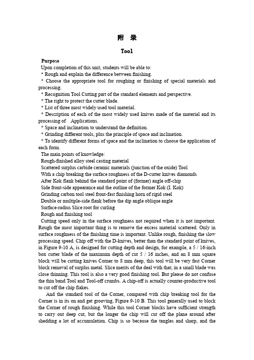
附录ToolPurposeUpon completion of this unit, students will be able to:* Rough and explain the difference between finishing.* Choose the appropriate tool for roughing or finishing of special materials and processing.* Recognition Tool Cutting part of the standard elements and perspective.* The right to protect the cutter blade.* List of three most widely used tool material.* Description of each of the most widely used knives made of the material and its processing of Applications.* Space and inclination to understand the definition.* Grinding different tools, plus the principle of space and inclination.* To identify different forms of space and the inclination to choose the application of each form.The main points of knowledge:Rough-finished alloy steel casting materialScattered surplus carbide ceramic materials (junction of the oxide) ToolWith a chip breaking the surface roughness of the D-cutter knives diamondsAfter Kok flank behind the standard point of (former) angle off-chipSide front-side appearance and the outline of the former Kok (I. Kok)Grinding carbon tool steel front-fast finishing horn of rigid steelDouble or multiple-side flank before the dip angle oblique angleSurface-radius Slice root for curlingRough and finishing toolCutting speed only in the surface roughness not required when it is not important. Rough the most important thing is to remove the excess material scattered. Only in surface roughness of the finishing time is important. Unlike rough, finishing the slow processing speed. Chip off with the D-knives, better than the standard point of knives, in Figure 9-10 A, is designed for cutting depth and design, for example, a 5 / 16-inch box cutter blade of the maximum depth of cut 5 / 16 inches, and an 8 mm square block will be cutting knives Corner to 8 mm deep, this tool will be very fast Corner block removal of surplus metal. Slice merits of the deal with that, in a small blade was close thinning. This tool is also a very good finishing tool. But please do not confuse the thin band Tool and Tool-off crumbs. A chip-off is actually counter-productive tool to cut off the chip flakes.And the standard tool of the Corner, compared with chip breaking tool for the Corner is in its on and get grooving, Figure 9-10 B. This tool generally used to block the Corner of rough finishing. While this tool Corner blocks have sufficient strength to carry out deep cut, but the longer the chip will cut off the plane around after shedding a lot of accumulation. Chip is so because the tangles and sharp, and theoperator is a dangerous, so this is a chip from the need to address the problem. Double, or triple the speed of the feed will help to resolve, but this will require greater horsepower and still easily chip very long. Because of the slow processing, however, this action will be a good tool but also because of the small root radius of the processing will be a smooth surface. Especially when processing grey cast iron especially.Cutting Tools appearanceAppearance, sometimes called the contour of the floor plan is where you see the vision or the top down or look at the surface. Figure 9-11 illustrate some of the most common form, those who could be on the cutting tools and grinding out successfully be used. National Standards in its thread-cutting tool on a tiny plane can be as GB thread, the Anglo-American unity and international standards screw threads. A special tool to outline the thread of the plane is to be ground into the correct size.Tools Corner fixedCorner to a number of knives around the 15 degree angle while the other knives and cutting of the straight. When the mill in Figure 9-12 A and 9-12 B, for example by the space and the inclination, these must factor into consideration in the review. Figure 9-12 B Tool Corner block the angle is zero, compared with 9-12 A map is a heavier cutting tools, and the 9-12 A map will take more heat. The same amount of space in front of the two cases are the same.Tool Corner block component and the angleFigure 9-13 Tool Corner block an integral part of the name, and plans 9-14 point of the name, is the machinery industry standards.Grinding Wheel Tool Corner BlockWhen the cutter is fixed in the middle of Dao, Tool Corner block can not be the grinding. Can not do so for the reasons: because of the large number of Dao and extra weight, making Corner together with the grinding is a clumsy and inefficient way. Too much pressure could be added to round on the sand. This can cause the wheel Benglie wheel or because of overheating and the rift on the Corner Tool damage. There are grinding to the possibility of Dao.GrindingA craftsman in his toolbox, should always be a small pocket lining grinding tool. Alumina lining a grinding tool as carbon tool steel and high speed steel tool tool. The silicon carbide lining grinding tool grinding carbide cutting tools. Cutting Tools should always maintain smooth and sharp edge, so that the life expectancy of long knives and processing the surface smooth.Cutting tool materialsCarbon tool steel cutter Corner block usually contains 1.3 percent to 0.9 percent of carbon. These make use of the cutting tool in their tempering temperature higher than about 400 degrees Fahrenheit (205 degrees Celsius) to 500 degrees Fahrenheit (260 degrees Celsius) remained hardness, depending on the content of carbon. These temperature higher than that of carbon tool steel cutter will be changed soft, and it will be the cutting edge. Damaged. Grinding blades or cutting speed faster when using carbon tool steel cutter will be made of the blue, this will be in the imagination. Toolwill be re-hardening and tempering again. So in a modern processing almost no carbon as a tool steel blade.Low-alloy steel cutting tool in the carbon steel tools added tungsten, cobalt, vanadium alloying elements such as the consequences. These elements and the hardness of high-carbon carbide. Increased tool wear resistance. Alloy tool steel that is to say there will be no hard and fast with hot red when the knife's edge can still continue to use it. Low-alloy steel cutting tool is relatively small for a modern processing.High-speed steel with tungsten of 14 percent to 22 percent, or Containing 1.5% to 6% of the W-Mo (molybdenum which accounted for 6 percent to 91 percent). From high-speed steel tool made of a rigid heat, some high-speed steel also contains cobalt, which is formed of rigid factor. Cobalt containing high-speed steel tool can maintain hardness, more than 1,000 degrees Fahrenheit (or 540 degrees Celsius) blade will become soft and easily damaged. After cooling, the tool will harden. When grinding, you must be careful because of overheating and cold at first, so that profile Benglie Zhucheng a variety of metal alloy materials have a special name called Carbide, such as containing tungsten carbide cobalt chrome. In little or iron carbide. However, its high-speed steel cutting speed than the maximum cutting speed is higher 25 percent to 80 percent. Carbide Tool General for cutting force and the intermittent cutting processing, such as processing Chilled Iron.The past, Carbide Tool is mainly used for processing iron, but now carburizing tool for processing all the metal.Carbide Tool into the body than to the high-speed steel tool or casting - lighter alloy cutting tools, because tend to be used as a tool carbide cutting tools. Pure tungsten, carbon carburizing agent or as a dipping formation of the tungsten carbide, suitable for the cast iron, aluminum, non-iron alloy, plastic material and fiber of the machining. Add tantalum, titanium, molybdenum led to the carbon steel The hardness of higher tool, this tool suitable for processing all types of steel. In manufacturing, or tungsten steel alloy containing two or more of a bonding agent and the mixture is hard carbon steel tool, is now generally containing cobalt, cobalt was inquiry into powder and thoroughly mixed, under pressure Formation of Carbide.These cutting tools in the temperature is higher than 1,660 degrees F (870 degrees C) can also be efficiently used. Carbide Tool hardware than high-speed steel tool, used as a tool for better wear resistance. Carbide Tool in a high-speed Gangdao nearly three times the maximum cutting speed of the cutting rate cutting.Made from diamonds to the cutting tool on the surface finish and dimensional accuracy of the high demand and carbide cutting tools can be competitive, but these tools processing the material was more difficult, and difficult to control. Metal, hard rubber and plastic substances can be effective tool together with diamonds and annoyance to the final processing.Ceramic tool (or mixed oxide) is mixed oxide. With 0-30 grade alumina mixture to do, for example, contains about 89 percent to 90 percent of alumina and 10 percent to 11 percent of titanium dioxide. Other ceramic tool is used with the tiny amount of the second oxides Mixed together the cause of pure alumina.Ceramic tools in more than 2,000 degrees F (1095 degrees C) temperature of the work is to maintain strength and hardness. Cutting rates than high-carbon steel knives to 50 percent or even hundreds of percentage. In addition to diamonds and titanium carbide, ceramic tool in the industry is now all the materials of the most hard cutting tool, especially at high temperatures.Tao structure easily broken in a specific situation, broken only carbon intensity of the half to two-thirds. Therefore, in cut, according to the proportion of cutting and milling would normally not be recommended. Ceramics cutting machine breakdown of failure is not usually wear failure, as compared with other materials, their lack of ductility and lower tensile strength.In short, the most widely used by the cutting tool material is cut high-speed steel, low alloy materials and carbide.Gap and dipSpace and inclination of the principle is the most easily to the truck bed lathe tool bladed knives to illustrate. Shape, size of the gap, and dip the type and size will change because of machining. Similarly a grinding tool Corner block is just like brushing your teeth.Gap tool to stop the edge of friction with the workpiece. If there is no gap in Figure 9-15A in the small blades, knives and the side will wear will not be cutting. If there are gaps in Figure 9-15 B, will be a cutting tool. This basic fact apply to any type of tool.Clearance was cutting the size depends on material and the cutting of the material deformation. For example, aluminum is soft and easy to slightly deformed or uplift, when the cutter Corner into space within the perspective and the perspective of the space under, the equivalent in steel mill and will very quickly broken. Table 9-1 (No. 340) that different materials grinding space and perspective.The correct amount of space will be properly protected edge. Too much space will cause the blade vibration (fibrillation), and may edge of total collapse. Tool Corner for the slab block must have a backlash, behind (in front) gap, knife and cut-corner. The main cutting edge is almost as all the cutting work at the cutting edge of the cutting tool on the edge, on the left or right-lateral knives, or cutting tool in the end, cut off on a cutter.Backlash angle for example, the role of a lathe tool Corner to the left block when it mobile. If there is no backlash Kok, Fig 9-16 A, with the only tool will be part of friction rather than cutting. If a suitable backlash Kok, Fig 9-16 B, will be cutting edge and will be well supported. If I have too many gaps, Fig 9-16 C, the edge will not support leading tool vibration (fibrillation) and may be completely broken.Tool gap to the front or rear of the role when it fixed to zero, as shown in Figure 9-17. If not in front of the Gap. Figure 9-17 A, the tool will not only friction and cutting. If a suitable space in front, Fig 9-17 B, but also a good tool will be cutting edge will be well supported. If a big gap in front of Ms, Fig 9-17 C, the tool will lack support, will have a vibrate, and cutting edge may be pressure ulcer.Figure 9-18 illustrate the gap in front of a lathe tool, when it with a 15 degree angle when fixed. The same amount of space on the front fixed to zero, and around thecutter, but the tool is the relatively thin. So the heat away from the blade less. Typically, front-side or front-not too big in Figure 9-19. It is usually from zero degrees to 20 degrees change, an average of about 15 degrees. There are clear advantages, according to the following: good cutting angle so that the cutting edge of the work was well, but relatively thin chips. Cutting Tools is the weakest part. By the former angle, the blade In the form of points around the workpiece. Cutting Edge shock will cause the entire tool vibration. When cutting the work nearly completed, the final section of metal was to ring, packing iron sheet or tangles in the form of the metal ball away gradually replaced by direct removal. Pressure tends to stay away from the workpiece cutting tool rather than narrow the gap between its parts. 9-19 A in the plan was an example of the use of a 30-degree lateral Cutting Angle tool processing thin slice example. A mathematical proof of the plan 9-19 B in the right-angle triangle trip is to expand the use of a map 9-19 A right triangle in the same way, that is, in the direction of upward mobility to feed a 0.010 inch. Right triangle adjacent to the edge (b) and feed 0.010 feet equivalent.The following formula using triangulation to explain:Kok cosine A = right-angle-B / C XiebianOr cosine of 30 degrees = b / c0.886 = b/0.010b = 0.866 * 0.010b = 0.00866 (bladed too thin)When the mobile tool, the purpose of front-to be processed to eliminate from the surface of the cut-cutting tools. This angle is usually from 8 degrees to 15 degrees, but in exceptional circumstances it as much as 20 degrees to 30 degrees. If there is no gap in Figure 9-20 A, cutting tools will be tied up, sharp beep, and the rivets may be the first to die away. The appropriate space, in Figure 9-20 B, cutting tool will be cutting well.A manufacturing plant or cut off the fast-cutter blade with three space, in a root-surface or surface and the other in bilateral level, in Figure 9-21. If a tool Corner block from the date of the face, It can have up to five space, in Figure 9-22. Grooving tool sometimes known as area reduction tool used to cut a groove in the shallow end of the thread.Inclination is the top tool inclination or, in the Tool Corner block on the surface. Changes depending on the angle of the cutting material. Improvement of the cutting angle, the blade shape, and guidelines from the chip from the edge of the direction. Chip dip under the direction named. For example, if a chip from the edge cutter outflow, it is called anterior horn. If the chip to the back of the outflow, that is, to the Dao, which is known as the horn. Some mechanical error and the staff horn as a front-or knife corner.Single tool like Tool Corner block may be the only edge of the blade side oblique angle, or in the back, only to end on the edge of the horn, or they may have roots in the face or front surface of the main Cutting edge of the blade and cutting edge of the horn and a roll angle of the portfolio. In the latter case, cut off most of the surface with a cutter and a chip to the point of view in the tool horn and roll angle in bothdirections has been moved out.Two different roll angle in Figure 9-23 A and 9-23 B was an example. Angle depends on the size and type of material was processed.9-24 A map in Figure 9-24 B and gives examples of zero to a fixed cutter after the two different angle. In Figure 9-25 B and 9-25 A Tool to the regular 15-degree angle. Figure 9-26 tool to display a 15 degree angle fixed, but in this case a tool to roll angle after angle and the combination of form close to the workpiece. Double or multiple chips to lead the inclination angle of a mobile or two away from the edge of the back and side to stay away from the cutter.Comparison of various horn, shown in Figure 9-27, Corner of the horn of a negative point of view, and zero is the point of view. These dip in the Corner cutter on the manifestation of a decision in the hands of the processing needs of the pieces. After Kok was the size of the type of materials processing, and knives in Dao fixed on the way.The type of lateral oblique angleFigure 9-28 examples of tools Corner blocks and four different types of lateral oblique angle of the cross-sectional. Figure 9-28 A, is zero lateral oblique angle, like some of the brass materials, some bronze and some brittle plastic material is particularly necessary. Standard side oblique angle, in Figure 9-28 B, is the most common one of the bevel side. In the ductile material on the deep cut, easy to chip in the tool around the accumulation of many, and this will cause danger to the operator. The chip will become a deal with the problem. Such a tool to cut off the grey cast iron is the most appropriate.Chip laps volumes, Figure 9-28 C, is one of the best types of inclination, especially in the ductile material on the special deep cutting. Chip small crimp in close formation against the Dao of bladed knives against the will of the rupture. The chip rolled up to maintain a narrow trough of the chip will guarantee that the width of closely Lane V ol. The chip is very easy to handle. V olume circle with a chip is not a cut-chip.Chip cut off, in Figure 9-28 D, leading to chip in the corner was cut off, and then to small chips fell after the chip. The need to cut off a chip provides up to 25 percent of the force. This inclination of the stickiness of the steel is good.Gap KokWhen cutting any material time, the gap should always be the smallest size, but the gap should never angle than the required minimum angle small space. The gap is too small knives Kok will lead to friction with the workpiece. Choice of space at the corner to observe the following points:1. When processing hardness, stickiness of the material, the use of high-speed steel tool cutting angle should be in the space of 6 to 8 degrees, and the use of carbon tool steel cutter at the corner of the gap in size should be 5 degrees to 7 degrees.2. When the processing of carbon steel, low carbon steel, cast iron when the gap angle should be the size of high-speed steel tool 8 degrees to 12 degrees, and carbon tool steel cutter 5 degrees to 10 degrees.3. Scalability when processing materials such as copper, brass, bronze, aluminum,iron, etc. Zhanxing materials, space Kok should be the size of high-speed steel tool 12 degrees to 16 degrees, carbon steel knives 8 degrees to 14 , Mainly because of the plastic deformation of these metals. This means that, when the cutter and around them, the soft metal to some minor deformation or protruding, and this tool will be friction. At this time, we must have a tool on the additional space.刀具目的在完成这一个单元之后,学生将会能够:* 解释粗加工和精加工之间的差别。
- 1、下载文档前请自行甄别文档内容的完整性,平台不提供额外的编辑、内容补充、找答案等附加服务。
- 2、"仅部分预览"的文档,不可在线预览部分如存在完整性等问题,可反馈申请退款(可完整预览的文档不适用该条件!)。
- 3、如文档侵犯您的权益,请联系客服反馈,我们会尽快为您处理(人工客服工作时间:9:00-18:30)。
外文资料翻译译文机械设计摘要:机器是由机械装置和其它组件组成的。
它是一种用来转换或传递能量的装置,例如:发动机、涡轮机、车辆、起重机、印刷机、洗衣机、照相机和摄影机等。
许多原则和设计方法不但适用于机器的设计,也适用于非机器的设计。
术语中的“机械装置设计” 的含义要比“机械设计”的含义更为广泛一些,机械装置设计包括机械设计。
在分析运动及设计结构时,要把产品外型以及以后的保养也要考虑在机械设计中。
在机械工程领域中,以及其它工程领域中,所有这些都需要机械设备,比如:开关、凸轮、阀门、船舶以及搅拌机等。
关键词:设计流程设计规则机械设计设计流程设计开始之前就要想到机器的实际性,现存的机器需要在耐用性、效率、重量、速度,或者成本上得到改善。
新的机器必需具有以前机器所能执行的功能。
在设计的初始阶段,应该允许设计人员充分发挥创造性,不要受到任何约束。
即使产生了许多不切实际的想法,也会在设计的早期,即在绘制图纸之前被改正掉。
只有这样,才不致于阻断创新的思路。
通常,还要提出几套设计方案,然后加以比较。
很有可能在这个计划最后决定中,使用了某些不在计划之内的一些设想。
一般的当外型特点和组件部分的尺寸特点分析得透彻时,就可以全面的设计和分析。
接着还要客观的分析机器性能的优越性,以及它的安全、重量、耐用性,并且竞争力的成本也要考虑在分析结果之内。
每一个至关重要的部分要优化它的比例和尺寸,同时也要保持与其它组成部分相协调。
也要选择原材料和处理原材料的方法。
通过力学原理来分析和实现这些重要的特性,如那些静态反应的能量和摩擦力的最佳利用,像动力惯性、加速动力和能量;包括弹性材料的强度、应力和刚度等材料的物理特性,以及流体润滑和驱动器的流体力学。
设计的过程是重复和合作的过程,无论是正式或非正式的进行,对设计者来说每个阶段都很重要。
最后,以图样为设计的标准,并建立将来的模型。
如果它的测试是符合事先要求的,则再将对初步设计进行某些修改,使它能够在制造成本上有所降低。
产品的设计需要不断探索和发展。
许多方案必须被研究、试验、完善,然后决定使用还是放弃。
虽然每个工程学问题的内容是独特的,但是设计师可以按照类似的步骤来解决问题。
产品的责任诉讼迫使设计人员和公司在选择材料时,采用最好的程序。
在材料过程中,五个最常见的问题为:(a)不了解或者不会使用关于材料应用方面的最新最好的信息资料;(b)未能预见和考虑材料的合理用途(如有可能,设计人员还应进一步预测和考虑由于产品使用方法不当造成的后果。
在近年来的许多产品责任诉讼案件中,由于错误地使用产品而受到伤害的原告控告生产厂家,并且赢得判决);(c)所使用的材料的数据不全或是有些数据不确定,尤其是当其性能数据长期不更新;(d)质量控制方法不适当和未经验证;(e)由一些完全不称职的人员选择材料。
通过对上述五个问题的分析,可以得出这些问题是没有充分理由而存在的结论。
对这些问题的研究分析可以为避免这些问题的出现而指明方向。
尽管采用最好的材料选择方法也不能避免发生产品责任诉讼,设计人员和工业界按照适当的程序进行材料选择,可以大大减少诉讼的数量。
从以上的讨论可以看出,选择材料的人们应该对材料的性质,特点和加工方法有一个全面而基本的了解。
在随后生产和售后服务的几年中,要接受新观念的变化,或者由试验和经验为基础,进一步分析并改进。
一些设计规则在本节中,建议要运用创造性的态度来替代和改进。
也许会创造出更实用、更经济、更耐用的产品。
为了激发创造性思维,下列是设计和分析的建议规则。
前六个规则对设计者来说特别适用。
1.要有创造性的利用所需要的物理性质和控制过程。
2.认识负载产生的影响及其意义。
3.预测没有想到的负载。
4.创造出对载荷更为有利的条件。
5.提供良好的应力分布和最小的刚度条件。
6.运用最简单的方程来优化体积和面积。
7.选择组合材料。
8.仔细选择所备的原料和不可缺少的组件。
9.调整有效的设计方案,以适应生产过程和降低成本。
10.规定好准确的位置条件为了使组件安装时不干涉。
机械设计包括一下内容:1.对设计过程、设计所需要公式以及安全系数进行介绍。
2.回顾材料特性、静态和动态载荷分析,包括梁、振动和冲击载荷。
3.回顾应力的基本规律和失效分析。
4.介绍静态失效理论和静态载荷下机械断裂分析。
5.介绍疲劳失效理论并强调在压力条件下接近高循环的疲劳设计,这通常用在旋转机械的设计中。
6.深入探讨机械磨损机理、表面接触应力和表面疲劳现象。
7.使用疲劳分析技术校核轴的设计。
8.讨论润滑油膜与滚动轴承的理论和应用。
9.深入介绍直齿圆柱齿轮的动力学、设计和应力分析,并简单介绍斜齿轮、锥齿轮和涡轮有关方面的问题。
10.讨论弹簧设计、螺杆等紧固件的设计,包括传动螺杆和预紧固件。
11.介绍盘式和鼓式离合器以及制动器的设计和技术说明。
机械设计一台完整机器的设计是一个复杂的过程。
机械设计是一项创造性的工作。
设计工程师不仅在工作上要有创造性,还必须在机械制图、运动学、工程材料、材料力学和机械制造工艺学等方面具有深厚的基础知识。
任何产品在设计时第一步就是选择产品每个部分的构成材料。
许多的材料被今天的设计师所使用。
对产品的功能,它的外观、材料的成本、制造的成本作出必要的选择是十分重要的。
对材料的特性必须事先作出仔细的评估。
仔细精确的计算是必要的,以确保设计的有效性。
在任何失败的情况下,最好知道在最初设计中有有缺陷的部件。
计算(图纸尺寸)检查是非常重要的。
一个小数点的位置放错,就可以导致一个本可以完成的项目失败。
设计工作的各个方面都应该检查和复查。
计算机是一种工具,它能够帮助机械设计师减轻繁琐的计算,并对现有数据提供进一步的分析。
互动系统基于计算机的能力,已经使计算机辅助设计(CAD)和计算机辅助制造(CAM)成为了可能。
心理学家经常谈论如何使人们适应他们所操作的机器。
设计人员的基本职责是努力使机器来适应人们。
这并不是一项容易的工作,因为实际上并不存在着一个对所有人来说都是最优的操作范围和操作过程。
另一个重要问题,设计工程师必须能够同其他有关人员进行交流和磋商。
在开始阶段,设计人员必须就初步设计同管理人员进行交流和磋商,并得到批准。
这一般是通过口头讨论,草图和文字材料进行的。
如前所诉,机械设计的目的是生产能够满足人类需求的产品。
发明、发现和科技知识本身并不一定能给人类带来好处,只有当它们被应用在产品上才能产生效益。
因而,应该认识到在一个特定的产品进行设计之前,必须先确定人们是否需要这种产品。
应当把机械设计看成是机械设计人员运用创造性的才能进行产品设计、系统分析和制定产品的制造工艺学的一个良机。
掌握工程基础知识要比熟记一些数据和公式更为重要。
仅仅使用数据和公式是不足以在一个好的设计中做出所需的全部决定的。
另一方面,应该认真精确的进行所有运算。
例如,即使将一个小数点的位置放错,也会使正确的设计变成错误的。
一个好的设计人员应该勇于提出新的想法,而且愿意承担一定的风险,当新的方法不适用时,就使用原来的方法。
因此,设计人员必须要有耐心,因为所花费的时间和努力并不能保证带来成功。
一个全新的设计,要求屏弃许多陈旧的,为人们所熟知的方法。
由于许多人墨守成规,这样做并不是一件容易的事。
一位机械设计师应该不断地探索改进现有的产品的方法,在此过程中应该认真选择原有的、经过验证的设计原理,将其与未经过验证的新观念结合起来。
新设计本身会有许多缺陷和未能预料的问题发生,只有当这些缺陷和问题被解决之后,才能体现出新产品的优越性。
因此,一个性能优越的产品诞生的同时,也伴随着较高的风险。
应该强调的是,如果设计本身不要求采用全新的方法,就没有必要仅仅为了变革的目的而采用新方法。
附件2:外文原文(复印件)Mechanical DesignAbstract:A machine is a combination of mechanisms and other components which transforms, transmits. Examples are engines, turbines, vehicles, hoists, printing presses, washing machines, and movie cameras. Many of the principles and methods of design that apply to machines also apply to manufactured articles that are not true machines. The term "mechanical design" is used in a broader sense than "machine design" to include their design. the motion and structural aspects and the provisions for retention and enclosure are considerations in mechanical design. Applications occur in the field of mechanical engineering, and in other engineering fields as well, all of which require mechanical devices, such as switches, cams, valves, vessels, and mixers.Keywords: Mechanical Design mechanisms Design ProcessThe Design ProcessDesigning starts with a need real.Existing apparatus may need improvements in durability, efficiency, weight, speed, or cost. New apparatus may be needed to perform a function previouslydone by men, such as computation, assembly, or servicing. With the objective wholly or partlyIn the design preliminary stage, should allow to design the personnel fully to display the creativity, not each kind of restraint. Even if has had many impractical ideas, also can in the design early time, namely in front of the plan blueprint is corrected. Only then, only then does not send to stops up the innovation the mentality. Usually, must propose several sets of design proposals, then perform the comparison. Has the possibility very much in the plan which finally designated, has used certain not in plan some ideas which accepts.When the general shape and a few dimensions of the several components become apparent, analysis can begin in earnest. The analysis will have as its objective satisfactory or superior performance, plus safety and durability with minimum weight, and a competitive cost. Optimum proportions and dimensions will be sought for each critically loaded section, together with a balance between the strengths of the several components. Materials and their treatment will be chosen. These important objectives can be attained only by analysis based upon the principles of mechanics, such as those of static for reaction forces and for the optimum utilization of friction; of dynamics for inertia, acceleration, and energy; of elasticity and strength of materials for stress and deflection; of physical behavior of materials; and of fluid mechanics for lubrication and hydrodynamic drives. The analyses may be made by the same engineer who conceivedthe arrangement of mechanisms, or, in a large company, they may be made by a separate analysis division or research group. Design is a reiterative and cooperative process, whether done formally or informally, and the analyst can contribute to phases other than his own. Product design requires much research and development. Many Concepts of an idea must be studied, tried, and then either used or discarded. Although the content of each engineering problem is unique, the designers follow the similar process to solve the problems.Product liability suits designers and forced in material selection, using the best program. In the process of material, the most common problems for five (a) don't understand or not use about the latest application materials to the best information, (b) failed to foresee and consider the reasonable use material may (such as possible, designers should further forecast and consider due to improper use products. In recent years, many products liability in litigation, the use of products and hurt the plaintiff accused manufacturer, and won the decision), (c) of the materials used all or some of the data, data, especially when the uncertainty long-term performance data is so, (d) quality control method is not suitable and unproven, (e) by some completely incompetent persons choose materials.Through to the above five questions analysis, may obtain these questions is does not have the sufficient reason existence the conclusion. May for avoid these questions to these questions research analyses the appearance indicating the direction. Although uses the best choice of material method not to be able to avoid having the product responsibility lawsuit, designs the personnel and the industry carries on the choice of material according to the suitable procedure, may greatly reduce the lawsuit the quantity. May see from the above discussion, the choice material people should to the material nature, the characteristic and the processing method have comprehensive and the basic understanding.Finally, a design based upon function, and a prototype may be built. If its tests are satisfactory, the initial design will undergo certain modifications that enable it to be manufactured in quantity at a lower cost. During subsequent years of manufacture and service, the design is likely to undergo changes as new ideas are conceived or as further analyses based upon tests and experience indicate alterations. Sales appeal.Some Rules for DesignIn this section it is suggested that, applied with a creative attitude, analyses can lead to important improvements and to the conception and perfection of alternate, perhaps more functional, economical,and durable products.To stimulate creative thought, the following rules are suggested for the designer and analyst. The first six rules are particularly applicable for the analyst.1. A creative use of need of physical properties and control process.2. Recognize functional loads and their significance.3. Anticipate unintentional loads.4. Devise more favorable loading conditions.5. Provide for favorable stress distribution and stiffness with minimum weight.6. Use basic equations to proportion and optimize dimensions.7. Choose materials for a combination of properties.8. Select carefully, stock and integral components.9. Modify a functional design to fit the manufacturing process and reduce cost.10. Provide for accurate location and noninterference of parts in assembly.Machinery design covers the following contents.1. Provides an introduction to the design process , problem formulation ,safety factors.2. Reviews the material properties and static and dynamic loading analysis , Including beam , vibration and impact loading.3. Reviews the fundamentals of stress and defection analysis.4. Introduces fatigue-failure theory with the emphasis on stress-life approaches to high-cycle fatigue design, which is commonly used in the design of rotation machinery.5. Discusses thoroughly the phenomena of wear mechanisms, surface contact stresses ,and surface fatigue.6. Investigates shaft design using the fatigue-analysis techniques.7. Discusses fluid-film and rolling-element bearing theory and application8. Gives a thorough introduction to the kinematics, design and stress analysis of spur gears , and a simple introduction to helical ,bevel ,and worm gearing.9. Discusses spring design including compression ,extension and torsion springs.10. Deals with screws and fasteners including power screw and preload fasteners.11. Introduces the design and specification of disk and drum clutches and brakes. Machine DesignThe complete design of a machine is a complex process. The machine design is a creative work. Project engineer not only must have the creativity in the work, but also must in aspect and so on mechanical drawing, kinematics, engineerig material, materials mechanics and machine manufacture technology has the deep elementary knowledge.One of the first steps in the design of any product is to select the material from which each part is to be made. Numerous materials are available to today's designers. The function of the product, its appearance, the cost of the material, and the cost of fabrication are important in making a selection. A careful evaluation of the properties of a. material must be made prior to any calculations.Careful calculations are necessary to ensure the validity of a design. In case of any part failures, it is desirable to know what was done in originally designing the defective components. The checking of calculations (and drawing dimensions) is of utmost importance. The misplacement of one decimal point can ruin an otherwise acceptable project. All aspects of design work should be checked and rechecked.The computer is a tool helpful to mechanical designers to lighten tedious calculations, and provide extended analysis of available data. Interactive systems, based on computer capabilities, have made possible the concepts of computer aided design (CAD) and computer-aided manufacturing (CAM).How does the psychologist frequently discuss causes the machine which the people adapts them to operate. Designs personnel''s basic responsibility is diligently causes the machine to adapt the people. This certainly is not an easy work, because certainly does not have to all people to say in fact all is the mostsuperior operating area and the operating process.Another important question, project engineer must be able to carry on the exchange and the consultation with other concerned personnel. In the initial stage, designs the personnel to have to carry on the exchange and the consultation on the preliminary design with the administrative personnel, and is approved. This generally is through the oral discussion, the schematic diagram and the writing material carries on.If front sues, the machine design goal is the production can meet the human need the product. The invention, the discovery and technical knowledge itself certainly not necessarily can bring the advantage to the humanity, only has when they are applied can produce on the product the benefit. Thus, should realize to carries on before the design in a specific product, must first determine whether the people do need this kind of product Must regard as the machine design is the machine design personnel carries on using creative ability the product design, the system analysis and a formulation product manufacture technology good opportunity. Grasps the project elementary knowledge to have to memorize some data and the formula is more important than. The merely service data and the formula is insufficient to the completely decision which makes in a good design needs. On the other hand, should be earnest precisely carries on all operations. For example, even if places wrong a decimal point position, also can cause the correct design to turn wrongly.A good design personnel should dare to propose the new idea, moreover is willing to undertake the certain risk, when the new method is not suitable, use original method. Therefore, designs the personnel to have to have to have the patience, because spends the time and the endeavor certainly cannot guarantee brings successfully. A brand-new design, the request screen abandons obsoletely many, knows very well the method for the people. Because many person of conservativeness, does this certainly is not an easy matter. A mechanical designer should unceasingly explore the improvement existing product the method, should earnestly choose originally, the process confirmation principle of design in this process, with has not unified it after the confirmation new idea.2.遇到无法理解的长句时,可以交给Google处理,处理后的结果猛一看,不堪入目,可是经过大脑的再处理后句子的意思基本就明了了;3.如果通过Google仍然无法理解,感觉就是不同,那肯定是对其中某个“常用单词”理解有误,因为某些单词看似很简单,但是在文献中有特殊的意思,这时就可以通过CNKI的“翻译助手”来查询相关单词的意思,由于CNKI的单词意思都是来源与大量的文献,所以它的吻合率很高。