指纹门禁接线图
门禁控制器接线原理图
门禁系统操作手册门禁控制器接线--原理图1一.设备特性:1.485控制器特性第一部分门禁控制器硬件手册门禁系统操作手册485 门禁控制器使用标准的工业串口通信,通信距离可达1200 米,每个总线可以接255 台设备,使用485 集线器可以扩展多条总线。
支持多达6 个输出和10 个输入。
型号有单门、双门、4门等。
⏹ 标准485(波特率9600)通讯;⏹ 大容量存储卡,54000 卡记录,60000 刷卡记录,10000 报警记录(控制器的记录保存在Flash 里面;双存储器,卡数据、刷卡记录分别存储,数据不易丢失;在脱机状况下,如果记录(刷卡记录和报警记录)超出容量,将覆盖最早的记录);⏹ 开门时区设置多达16 组,且可以分别设定对应的多种开门方式,如卡、卡+密码、密码、双卡、首卡开门等;⏹ 支持远程操作开关门、远程开关火警、报警。
支持软件锁门常闭功能;⏹ 支持多个报警事件的报警输出,如无效卡、无效时间、门报警、门开超时等;⏹ 默认支持2—4个weigend 读卡器,自动适应26、34、37协议;⏹ 支持多达6 个输出,分别控制门和报警输出联动;⏹ 多门控制器支持互锁、防潜返功能;⏹ 所有设备可以混合安装在一个系统里面;⏹ 配合软件支持考勤、实时在线巡更功能。
支持多用户多机实时管理监控;⏹ 内置web 网页,同时可以网络实时监控;2.T CP/IP控制器特性以太网门禁控制器是专门为对通信要求比较高而设计的门禁设备。
具有远程升级、远程初始化、数据复位、防区功能的功能;可以扩展的485 接口空间;支持多达6个输出和10 个输入。
是一个可以通过以太网进行远程管理的门禁系统。
型号有单门、双门、4门等。
⏹ 标准10M TCP/IP 通讯;⏹ 大容量存储卡,支持远程升级版卡容量4000,刷卡记录4000,报警记录6000;⏹ 标准版卡容量54000,刷卡记录60000,报警记录20000(控制器的记录保存在Flash 里面。
门禁控制器接口及接线图
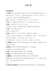
门禁控制器接口及接线图
在接线前,确保把电源关断,在通电状态下接线可能会对设备造成严峻的损坏。
下为ACM2110接口示意图。
图1 ACM2110掌握器接口示意图ACM2110掌握器电源线连接时对电源的要求,额定电压AC/DC 24V±30%,额定电流最大800mA。
ACM2110掌握器与电源的连接引脚集中于TB1模块,下为掌握器与电源的连接示意图。
系统的主电源可以仅使用电池或沟通市电供电,也可以使用沟通电源转换为低电压直流供电。
可以使用二次电池及充电器、ups电源、发电机作为备用电源。
系统仅使用电池供电时,电池容量应保证系统正常开启10000次以上。
系统使用备用电池时,电池容量应保证系统连续工作不少于48h,并在其间正常开启50次以上。
图2 掌握器电源连接示意图ACM2110采纳半双工RS-485通讯总线,网络上第一个和最终一个掌握器之间的距离不能超过1200米,ACM2110掌握器与电源的连接引脚集中于TB2模块,下为掌握器与RS485的连接示意图。
图3 掌握器与RS485 连接示意图
本案中共用到4块2110掌握器,其中只能有一块为主掌握器用于连接上位机安装门禁管理软件实现对系统的综合管理,其余为终端
掌握器,详细设置可通过对各掌握器J1、J2模块的跳线实现,如下图所示。
图4 掌握器跳线示意图。
门禁控制器接线原理图

门禁控制器接线原理图2008-08-08 初始版本完成2010-11-18 升级版本门禁系统操作手册版本: 2.0版本: 2. 11一.设备特性:1.485控制器特性第一部分门禁控制器硬件手册门禁系统操作手册485 门禁控制器使用标准的工业串口通信,通信距离可达 1200 米,每个总线可以接 255 台设备,使用485 集线器可以扩展多条总线。
支持多达 6 个输出和 10 个输入。
型号有单门、双门、4门等。
✍✍✍✍✍标准 485(波特率 9600)通讯;✍✍✍✍✍大容量存储卡,54000 卡记录,60000 刷卡记录,10000 报警记录(控制器的记录保存在 Flash 里面;双存储器,卡数据、刷卡记录分别存储,数据不易丢失;在脱机状况下,如果记录(刷卡记录和报警记录)超出容量,将覆盖最早的记录);✍✍✍✍✍开门时区设置多达 16 组,且可以分别设定对应的多种开门方式,如卡、卡+密码、密码、双卡、首卡开门等;✍✍✍✍✍支持远程操作开关门、远程开关火警、报警。
支持软件锁门常闭功能;✍✍✍✍✍支持多个报警事件的报警输出,如无效卡、无效时间、门报警、门开超时等;✍✍✍✍✍默认支持 2—4个 weigend 读卡器,自动适应 26、34、37协议;✍✍✍✍✍支持多达 6 个输出,分别控制门和报警输出联动;✍✍✍✍✍多门控制器支持互锁、防潜返功能;✍✍✍✍✍所有设备可以混合安装在一个系统里面;✍✍✍✍✍配合软件支持考勤、实时在线巡更功能。
支持多用户多机实时管理监控;✍✍✍✍✍内置 web 网页,同时可以网络实时监控;2.T CP/IP控制器特性以太网门禁控制器是专门为对通信要求比较高而设计的门禁设备。
具有远程升级、远程初始化、数据复位、防区功能的功能;可以扩展的 485 接口空间;支持多达6个输出和 10 个输入。
是一个可以通过以太网进行远程管理的门禁系统。
型号有单门、双门、4门等。
✍✍✍✍✍标准 10M TCP/IP 通讯;✍✍✍✍✍大容量存储卡,支持远程升级版卡容量 4000,刷卡记录 4000,报警记录 6000;✍✍✍✍✍标准版卡容量 54000,刷卡记录 60000,报警记录 20000(控制器的记录保存在 Flash 里面。
门禁系统接线图
门禁系统接线图
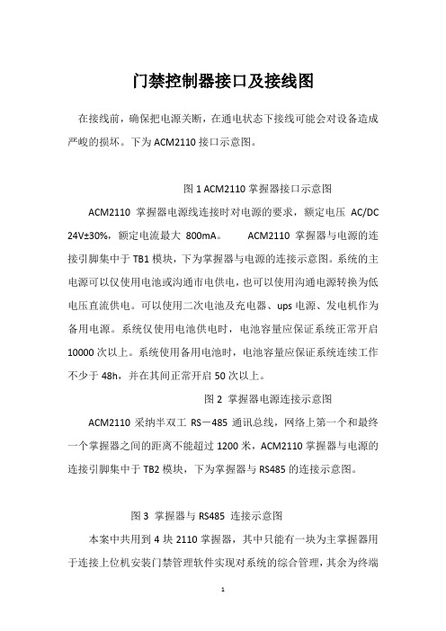
TB2接线端子: TB2端子是读卡器的接线端子
TB3接线端子:
TB3接线端子是门禁控制器485通信接线端子,485是总线连接方式,接线
方法需要严格按照485总线的标准,严禁使用“星型连接”和“分岔连接的方法”;
485总线理论上最长可以连接1200米,但是要根据现场环境如:线材质量,
设备485芯片带载能力、环境噪声、电磁干扰等实际情况综合考虑布线;
如果通信距离大于200米,那么需要在485总线的两个终端个加120欧的电阻;
控制器到485总线的距离应该远小于485总线上相邻设备之间的距离; TB7接线端子 :
TB9接线端子 : TB9接线端子是控制门锁继电器的输出端, HSWP-880需要每个门都有门禁专用电源;具体的接线方法如下;
TB9接线端子图。
门禁磁力锁安装接线示意图
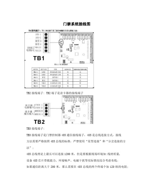
门禁磁力锁安装接线示意图为了确保人身安全,门禁接线过程需要在关闭所有电源的情况下进行。
1、先给门禁电源接220V的电。
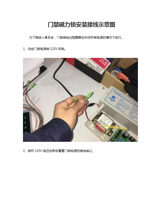
2、接好220V电压后再来看看门禁电源的接线端口。
3、以下有10个接线端子,NO跟COM接电控锁的,NC跟COM接磁力锁,12V跟GND给门禁一体机供电,GND跟PUSH接开门信号,接下来先接磁力锁,磁力锁就红黑两根线,如下图。
4、红色线接NC,黑色线COM,首先把12V电源线接。
5、红色是12V正极,黑色12V负极。
6、接下来接开门按钮。
7、接下来再看门禁电源的按钮线,GND跟PUSH,下图。
8、这就接好了开门按钮这头接的是GND跟PUSH,门禁接线完成。
中控门禁机接线示意图
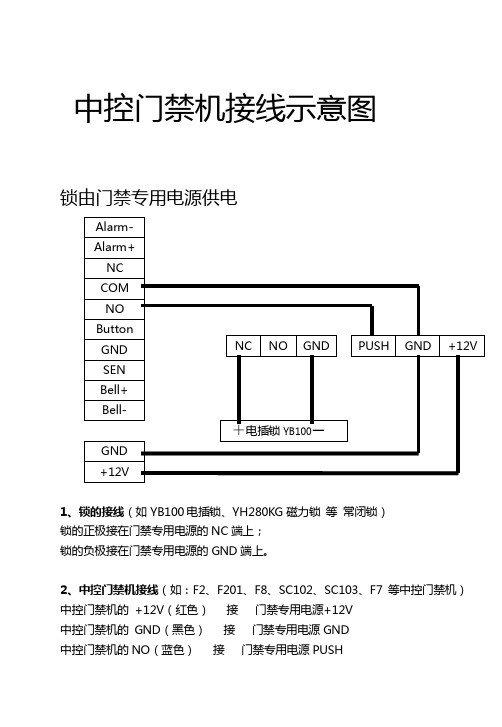
中控门禁机接线示意图
锁由门禁专用电源供电
1、锁的接线(如YB100电插锁、YH280KG磁力锁等常闭锁)
锁的正极接在门禁专用电源的NC端上;
锁的负极接在门禁专用电源的GND端上。
2、中控门禁机接线(如:F2、F201、F8、SC102、SC10
3、F7 等中控门禁机)中控门禁机的+12V(红色)接门禁专用电源+12V
中控门禁机的GND(黑色)接门禁专用电源GND
中控门禁机的NO(蓝色)接门禁专用电源PUSH
中控门禁机的COM(红色)接门禁专用电源GND
注:中控门禁机的GND和COM可以并接在一起,然后同时接到门禁专用电源上的GND上。
锁由中控门禁机直接供电
1、锁
锁的正极接在中控门禁机的NC(黄色)端上;
锁的负极接在中控门禁机的GND(黑色)端上。
2、中控门禁机
中控门禁机的COM(红色)需并上中控门禁机的+12V(红色)上。
中控门禁机外接DC12V报警器
1.中控门禁机的AL+(橙色)和中控门禁机的+12V(红色)并在一起2.AL-(绿色)接DC12V报警器正极
3.GND(黑色)接DC12V报警器负极
中控门禁机外接有线门磁
1、接线:
中控门禁机的SEN(白色)和中控门禁机的GND(黑色)分别接在门磁的两端,没有正负之分。
2、设置:
进入中控门禁机的设置界面,“设置”—→“门禁功能设置”—→“门磁开关”—→设置为“常闭”,则在门磁处于断开状态时,报警器报警,也就是相当于门打开了报警。
在主菜单下按“解除报警”可解除报警。
中控门禁机外接交流AC~220V报警器。
四门门禁接线图
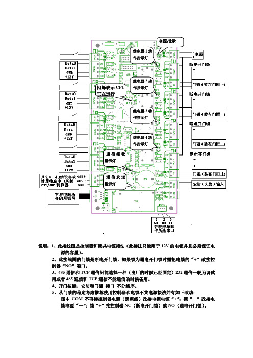
说明:1、此接线图是控制器和锁共电源接法(此接法只能用于12V 的电锁并且必须保证电
源的容量)。
2、此接线图的门锁是断电开门锁,如果锁为通电开门锁时需把电锁的“+”改接控
制器“NO ”端口。
3、485通信和TCP 通信只能选择一种(出厂的时候已经固定)232通信一般为调试
用或者485通信和TCP 通信不能通信的时候备用。
4、开门按键、安防和门磁 接口 不分线序。
5、从门禁的稳定考虑推荐使用控制器和电锁不共电源接法并有如下改动:
图中COM 不再接控制器电源(黑粗线)改接电锁电源“+”;锁“—”改接电
锁电源“—”;锁“+”接控制器NC (断电开门锁)或NO (通电开门锁)。
继电器2动
作指示灯
继电器3动
作指示灯
继电器4动
作指示灯
闪烁表示CPU
正在运行 通信接收
指示灯
通信发送
指示灯。
指纹门禁机连线说明(中英繁中性)

Quick Connection Guide1、Connection between controller terminal and power supplyController’s terminal is shown in below figure. It supports DC power supply of 9-15V as input, and can work immediately through the direct connection between GND and +12V. If lock-control uses the individual power supply, the current of controller’s power supply adapter applies matching current of 500mA or over, if lock-control uses the only power supply with controller, the nominal output current of the power adapter will exceed the working current by over 1000mA.2、Connection with door lockController can support normal-open and normal-closed door lock simultaneously, so long as it is connected with the different terminals respectively. Usually, Lock NO terminal disconnects with COM terminal, and they will connect when controller outputs the unlocking signal and recover to disconnection when the signal ends. The connection and disconnection between Lock NC terminal and COM terminal is opposite to above situation, they connect usually and disconnect when the unlocking signal is output.Due to the existence of varied electric-control door locks, the correct connection method must be confirmed in accordance with the door lock specification: Lock NO terminal should be used for the locks, which unlock when the power is on and lock when power is off; otherwise, the Lock NC terminal should be used.Take the electric-control lock, for example herein, to show the connection method between controller and locks. Use Lock NO terminal when controller is connected with the lock, which locks usually when power is off.1) Connecting method for power supply adapter serving for both controller and door lock contemporarily.1. Matching voltage of lock must be 9 to 15V;2. Matching voltage of adapter must be accordant with that of lock;3. Matching output current of adapter must exceed the working current by over 1000mA.2)Connecting method for controller and door lock using separated power supply adapter.1.Matching voltage of lock is DC24V~3A,AC220V~1A.2.Matching voltage of lock’s power supply adapter must b e accordant with that of lock, and the output current must exceed the working current of the lock.3. working current of the lock must less than 2000mA.3)Connection between controller and locks, which control the high current1.Matching voltage of lock’s power supply adapter must be accordant with that of lock, and the output current must exceed the working current of the lock.2.Matching voltage and current of relay must exceed those of the lock.3、Connection with exit-door button, door magnetism, doorbell and WarnerExit-door button is installed in the inside room, and you can open the door when the button is closed. The door magnetism is used to inspect the opening and closing state of the door, and controller can detect the state when the door is opened unauthorised, and hence output the alarming signal. Furthermore, controller will also output the alert signal if the door is not closed well within the specified time.Alarming output of controller is a switch signal, and can be connected in series into the power loop of warner. Of course it can be used as the trigger signal of advanced alarming/monitoring system.Doorbell terminal of controller is connected with the doorbell button of panel, so what you need to do is to rang the doorbell button switches to a series connection of 5-15 V DC power supply and connected to the two terminals.4、Connection with controllerController offers the standard Wiegand26 output, and can be connected with existing most Access Controller as connection with an ID card reader or password keyboard.Controller can connect with PC through RS232 or Ethernet(selectable)5、Connect with network or computerController offers RS232 and RS485 interface, and selectable Ethernet interface to connect with PC or to build network.RS485 NetworkA BController is connected with RS485 network门禁快速接线指南1、门禁接线端子与电源连接门禁的接线端子如下所示。