HASUNCAST常用产品选择指南
沙多玛产品功能应用选择指南(中文版)

Saret521&522 Ricon153&154
SR-507
橡胶轮
增加活度降低粘度附着力
耐用性硬度
Saret516&517Ricons153,154
Saret75 EPMA2A&2M
模具产品
耐热性,热撕裂低压永快硫
Sarets516 521 634SR-507 SR-525
机车密封件
环氯基地面涂料
快速低温硫化硬度的增加高光和抗湿性
SR-238 CD-564 CD-582 M-Cure201
M-Cure300 M-Cure-400
丙烯酸涂料
环氧组二次反应
SR-379
胶粘与密封体
PVC橡胶的弹性
粘度降低抗冲击力耐热耐水
SR-209 SR-297 SR-350 SR-399
SR-9009 SB-600
物品涂料
尺寸稳定性抗划性硬度
SR-205 SR-213 SR-239 SR-350
CD-570 CD-572 SR-252 SR-740
乳液涂料树脂
耐用性光泽粘接力
SR-313 SR423 SR-511 SR-350
合成
SR-495 SR-604 SR-444 SR-295
环氧树脂体
快速低温硫化
SR-351 SR-295 M-Cure400
SR-206 SR-214 SR-231 SR-239
PC-201 SR-350
层压树脂
低喷射,高温屈挠性
SR-206 CD-541 PC-301 PC-304
SMC/BMC
高温性
PC-301 PC-304 SR-350
沙多玛产品功能应用选择指南
MKS 产品选择指南说明书

Downstream Pressure Controllers and ValvesPRODUCT SELECTION GUIDE651, 1651, 153, 253, 653, aND hEaTED VaLVESIsolating and close-loop controlling each variable that affects a vacuum process is the best method for achieving process consistency. At MKS, we can isolate and close-loop control process pressure using a throttling control valve and a digital PID or self-tuning pressure controller. A typical pressure control system works as follows: (1) a Baratron ® capacitance manometer senses pressure in a vacuum chamber; (2) this pressure is then compared to the desired set point pressure in the pressure controller; and (3) the pressure controller commands the control valve to open or close, changing the chamber pressure and bringing it to the desired process pressure set point.No one pressure control technique is best for all applications, though the downstream control technique is chosen most often for today’s more critical vacuum processes (see chart below). With the downstream control technique, an exhaust throttle valve is opened or closed, changing the conductance to the vacuum pump in order to achieve and maintain the desired process pressure—independent of gas inlet. The downstream pressure control technique provides high dynamic range, works well with all types of vacuum pumps, provides fast response, is tolerant to most effluent gases, and has moderate initial costs.Pressure Control T echniquesValveW W W .M K S I N S T .C OM1651The 1651 is a display-less version of the 651 for OEMdesign engineers who wish to completely control theirprocess via a host computer. Offered as an economicalalternative to the 651, this “black box” version allowsfor remote setup or control entirely through rear panelinterface—RS-232, TTL, or analog. Its compact size allowsfor installation anywhere on the process system, savingvaluable rack space.651The 651 Self-tuning/Digital PID Valve Controller drives653 or 253 Exhaust Throttle Valves with speed andprecision. Its self-tuning algorithm brings the system toset point faster than conventional controllers, and ensuresrepeatable process recipes without operator involvement.The self-tuning function determines optimal controlparameters for any set point in the range of the valve bylearning time constants, transfer functions of the valve andplumbing, valve gain, and other important parameters.The 651 includes adjustable soft-start functions for eachset point, as well as open and close functions to minimizeturbulence in the chamber; local/remote transducerzeroing capability; and two relays to activate other systemfunctions, or to indicate if the pressure deviates fromthe desired set point. All controls are easily accessedvia a simple-to-use front panel, or remotely through RS-232, TTL, or analog voltage. An LCD readout showsvalve position and displays pressure in a wide range ofengineering units. Five reprogrammable set points areprovided for pressure or position control.Self-T uning/Digital PIDPressure ControllersPressure Controllers andExhaust Throttle Valves“Smart” Exhaust Throttle Valve253The 253 Exhaust Throttle Valve regulates the removal of gas from a processing system. Its flapper is positioned to modulate gas flow, thereby controlling process pressure. The 253 has a non-linear actuator placed between the flapper shaft and the motor drive shaft in order to generate a linear valve transfer characteristic and provide smooth linear pressure control. The 253 is available in standard sizes and flange styles, and is compatible with all MKS throttle valve controllers.Exhaust Throttle Valve153Specifically designed for computer-controlled applications where a simple pressure control system is desired, the 153 Valve integrates all control, communication, and driver circuits via a compact “add-on” electronics module within a 253 Throttle Valve assembly, eliminating the need for a separate pressure control electronics module. The 153 is operable in two modes, flapper positioning or pressure control.For DeviceNet ™ communications consult Applications Engineering on the 683.653The 653 high-speed motor and gear/driver assembly provides fast response to a given set point to quicklyachieve desired pressure and increase system throughput. High accuracy is attained by micro-stepping the flapper to give more precise control, and no drift, of pressure at the desired set point. The 653 has sufficient torque to operate sealing valves up to four inches and non-sealing valves to 12 inches to prevent clogging from contamination buildup. The valve body can be heated up to 150°C (using optional sealing materials) for operation in high temperature applications and processes. The 653 has a flapper position indicator to identify valve angle during systemtroubleshooting, is available in a variety of sizes and flangestyles, and is compatible with 651 and 1651 Controllers.Exhaust Throttle Valve withHigh-speed Motor/Gear AssemblyIPS SubsystemCurrent trends in semiconductor processing are towards less maintenance, more uptime, and increased product yield. Reduction of the solid buildup resulting from thecooling of effluent gases can be a factor in achieving those goals. Heating the valve and other components of the system is part of a method to manage these byproducts, increasing uptime, and improving wafer yields, with a quick payback.IPS offers subsystems to improve heat distribution on downstream lines while complying with strict agency andcorporate personnel safety standards.HeatersDownstream Pressure Controllers Pressure ControllerSpecifications651C 1651CValves Operated 653 and 253 Exhaust 653 and 253 ExhaustThrottle ValvesThrottle ValvesPressure Input Signal 0-10 VDC, 0-5 VDC, or 0-1 VDC, 0-5 VDC, 0-10 VDC, 0-1 VDC,selectableselectable Input Power Required 90-132 or 180-264 VAC, 50/60 Hz ±15 VDC ±5% Minimum Input CurrentFor 653 Valve: 1 Amp +transducercurrentFor 253 Valve: 0.5 Amp + transducer current Maximum Input CurrentNot to exceed 7 AmpsSet PointsProgrammable 5 total, programmable in any5 total, programmable in anycombination for pressure or combination for pressure or position (adjustable from the position (adjustable via RS-232;front panel or RS-232; selectable selectable via TTL or RS-232)from the front panel, TTL,or RS-232)External analog 1; pressure or position, 1; pressure or position,0-5 or 0-10 VDC0-5 or 0-10 VDC Controller Repeatability±0.1% of F .S.±0.1% of F .S.ambient Operating Temperature 15°-40°C (60°-104°F)15°-50°C (60°-122°F)Output PowerStandard:±15VDC±********Available to external transducers: (Derated to 0.4 Amp with 90-99±15 Volts @ 3 Amps max. (90 Watts) or 180-198 VAC input) when powered from an external power supply withOptional: ±15 VDC ±5% @ 1.5a capacity of ±15 Volts @ 5 Amps (150Ampsmax. Watts)analog Output Signal0-5 or 0-10 VDC for 0-100% 0-5 or 0-10 VDC for 0-100%valve position and 0-10 VDC valve position and 0-10 VDCfor 0-100% F .S. pressure for 0-100% F .S. pressure Size1/2-rack packaging: 3 1/2” H x 6.7”W x 9.15”D3-1/2”H x 9-1/2”W x 9”DDisplay2-line LCD with 4-1/2 place readout N/A(pressure and valve position)Display Units T orr, mT orr, mbar, Pascal, N/A cmH 2O, inH 2O, µbar, kPaSoft StartStandard Standard Self-tuning Unit Standard Standard PID Control Standard Standard Remote Zero Standard StandardInterface Front panel, Analog, TTLAnalog, TTL (16 inputs, 6 outputs)(16 inputs, 6 outputs) and RS-232 and RS-232Relay Outputs 2, process limits: 24 Volts AC/DC 2, process limits: 24 Volts VDC @@ 1 Amp resistive1 Amp resistive Remote Control Override Standard Standard (Open, Close, hold)Position Control Capability Standard StandardConnectors Valve: 9-pin Type “D” female Power Connector: 9-pin Type “D” male I/O: 37-pin Type “D” femaleValve: 9-pin Type “D” female Transducer: 15-pin Type “D” female I/O: 37-pin Type “D” female RS-232: 9-pin Type “D” male Transducer: 15-pin Type “D” femaleRS-232: 9-pin Type “D” male ComplianceCECE653B 253B Speed (open to close) 1.7 sec Standard: 7.5 sec. Optional: <2 sec. (Note 1)Resolution1/12,000 Standard: 1/10,000Fast Motor Option: 1/2800Drive MethodDirect gear drive Mechanical (non belt) drive with integral cosinegenerator to linearize valve transfer characteristic Maximum Valve Body Standard: 0°C-100°C 0°-90°C Operating Temperature Optional: 0°C-150°C (Note 1)Valve Motor ambient -20°C to +40°C 0°C-70°C max. Operating Temperature Differential Pressure 1 atm. (15 psig) max. 1 atm. (15 psig) across Valve External Leakage at 1x10⁻⁸ scc/sec He1x10-7 scc/sec He Shaft SealMaterials Exposed Standard: 316L S.S., Viton ® (Note 2) 316 S.S., Viton (Note 2) to ProcessCompatible Controller651, 1651651, 1651, 153Visual Position Indicator Standard N/ADrive Output Torque 800 in-oz Standard speed: 600 in-oz (with 651 Controller)High-speed: 170 in-oz Closed Leakage <10-7 (T orr l/s) <10-7 (Torr l/s)(valves with a flapper o-ring) Notes:1) Consistent with shaft seal and flapper seal o-ring material.2) Where Viton is used, other materials are available.Contact Applications Engineering.Throttle Valve Specifications (Common to All Sizes & Flanges)Notes:1) Fast Motor Option only available onnon-sealing valves.2) Where Viton is used, other materials are available. Contact Applications Engineering.Dimensional Drawings Exhaust Throttle Valve Sizes and Flange Styles ASA Flanges253B(a) (B) (C) (D) (E)(**)Nominal NumberFlangeFlange Controllable PartMounting Inside Outside Bolt hole of Bolt Overall Bolt Circle O-ring Flapper O-ring Conductance l/s Number Flange Diameter Diameter Thickness Diameter holes height* Diameter Groove ID O-ring Parker No. min (max)253B-2-2-1 2” ASA 1.88 (48) 5.95 (151) 0.75 (19) 0.75 (19) 4 10.79 (274) 4.750 (121) 3.365 (85) Y es 2-237 0.35 300253B-2-2-2 2” ASA 1.95 (50) 5.95 (151) 0.75 (19) 0.75 (19) 4 10.79 (274) 4.750 (121) 3.365 (85) No 2-237 0.7 300253B-60-2-2 2” ASA 2.362 (60) 5.95 (151) 0.75 (19) 0.75 (19) 4 10.79 (274) 4.750 (121) 3.365 (85) No 2-237 0.8 375253B-3-2-2 2” ASA 3.025 (77) 5.95 (151) 0.75 (19) 0.75 (19) 4 10.79 (274) 4.750 (121) 3.365 (85) No 2-237 1 500253B-3-3-2 3” ASA 3.025 (77)7.40 (188)0.88 (22) 0.75 (19) 4 12.24 (311) 6.000 (152) 4.475 (114) No 2-349 1 500253B-3-3-2 3” ASA 3.965 (101) 7.40 (188) 0.88 (22) 0.75 (19) 4 12.24 (311) 6.000 (152) 4.475 (114) No 2-349 1.5 950253B-4-4-24” ASA3.965 (101) 8.90 (226)0.88 (22)0.75 (19)813.74 (349) 7.500 (191) 5.995 (152)No2-258 1.5 950*For 153 Valves, add 1.93” (49mm) to the 253 Dimension** Molecular flow regime653B(a) (B) (C) (D) (E) (**)Nominal Number FlangeFlange Controllable Part Mounting Inside Outside Bolt hole of Bolt Overall Bolt Circle O-ring Flapper O-ring Conductance l/s Number Flange Diameter Diameter Thickness Diameter holes height Diameter Groove ID O-ring Parker No. min (max)653B-2-2-1 2” ASA 1.886 (48) 5.95 (151) 1.00 (25) 0.75 (19) 4 12.53 (318) 4.750 (121) 3.365 (85) Y es 2-237 0.35 300653B-2-2-2 2” ASA 1.886 (48) 5.95 (151) 1.00 (25) 0.75 (19) 4 12.53 (318) 4.750 (121) 3.365 (85) No 2-237 0.7 300653B-60-2-1 2” ASA 2.360 (60) 5.95 (151) 1.00 (25) 0.75 (19) 4 12.53 (318) 4.750 (121) 3.365 (85) Y es 2-237 0.4 375653B-60-2-1 2” ASA 2.360 (60) 5.95 (151) 1.00 (25) 0.75 (19) 4 12.53 (318) 4.750 (121) 3.365 (85) Nos 2-237 0.8 375653B-3-2-1 2” ASA 2.886 (73) 5.95 (151) 1.00 (25) 0.75 (19) 4 12.53 (318) 4.750 (121) 3.365 (85) Y es 2-237 0.5 500653B-3-2-2 2” ASA 2.886 (73) 5.95 (151) 1.00 (25) 0.75 (19) 4 12.53 (318) 4.750 (121) 3.365 (85) No 2-237 1 500653B-3-3-1 3” ASA 2.886 (73) 7.40 (188) 1.00 (25) 0.75 (19) 4 14.02 (356) 6.000 (152) 4.475 (114) Y es 2-349 0.75 500653B-3-3-2 3” ASA 2.886 (73) 7.40 (188) 1.00 (25) 0.75 (19) 4 14.02 (356) 6.000 (152) 4.475 (114) No 2-349 1 500653B-4-3-1 3” ASA 3.885 (99) 7.40 (188) 1.00 (25) 0.75 (19) 4 14.02 (356) 6.000 (152) 4.475 (114) Y es 2-349 0.75 950653B-4-3-2 3” ASA 3.885 (99) 7.40 (188) 1.00 (25) 0.75 (19) 4 14.02 (356) 6.000 (152) 4.475 (114) No 2-349 1.5 950653B-4-4-1 4” ASA 3.885 (99) 8.90 (226) 1.00 (25) 0.75 (19) 8 15.54 (395) 7.500 (191) 5.995 (152) Y es 2-258 0.75 950653B-4-4-2 4” ASA 3.885 (99)8.90 (226)1.00 (25) 0.75 (19) 8 15.54 (395) 7.500 (191) 5.995 (152) No 2-258 1.5 950653B-6-4-1 4” ASA 5.503 (140) 8.90 (226)1.62 (41)0.75 (19) 8 16.16 (410) 7.500 (191) 5.995 (152) No 2-258 4 2150653B-6-6-2 6” ASA 5.869 (149) 10.90 (277) 1.62 (41) 0.88 (22) 8 18.18 (462) 9.500 (241) 8.000 (203) No 2-266 4 2150653B-8-6-2 6” ASA 7.636 (194) 10.90 (277) 1.62 (41) 0.88 (22) 8 18.18 (462) 9.500 (241) 8.000 (203) No 2-266 6 3600653B-8-8-28” ASA7.636 (194) 13.19 (335) 1.62 (41) 0.88 (22) 8 20.48 (520 11.750 (298) 9.750 (248)No2-273 8 3600653B-10-10-2 10” ASA 10.118 (257) 16.00 (406) 1.62 (41)1.00 (25)1223.31 (592)14.250 (362) 11.938 (362) No2-278106400Dimensions in inches (mm)** Molecular flow regimeCF Flanges253B(a) (B) (C) (D) (E) (**)Nominal Number ControllablePart Mounting Inside Outside Bolt hole of Bolt Overall Bolt Circle Flapper Conductance l/sheight*DiameterO-ringholesmin (max)DiameterDiameterNumber FlangeThicknessDiameter253B-20-2CF-1 2 3/4” CF 0.779 (20) 2.75 (70) 1.25 (32) 0.26 (6.6) 6 8.64 (220) 2.312 (59) Y es 0.07 24 253B-20-2CF-2 2 3/4” CF 0.779 (20) 2.75 (70) 1.25 (32) 0.26 (6.6) 6 8.64 (220) 2.312 (59) No 0.25 31 253B-1-2CF-1 2 3/4” CF 1.270 (32) 2.75 (70) 1.25 (32) 0.26 (6.6) 6 8.64 (220) 2.312 (59) Y es 0.2 50 253B-1-2CF-2 2 3/4” CF 1.270 (32) 2.75 (70) 1.25 (32) 0.26 (6.6) 6 8.64 (220) 2.312 (59) No 0.4 55 253B-2-3CF-1 3 3/8” CF 1.889 (48) 3.25 (83) 1.06 (27) 0.33 (8.3) 8 9.14 (232) 2.850 (72) Y es 0.35 300 253B-2-3CF-2 3 3/8” CF 2.000 (51) 3.25 (83) 1.06 (27) 0.33 (8.3) 8 9.14 (232) 2.850 (72) No 0.7 300 253B-2-4CF-2 4 1/2” CF 2.000 (51) 4.47 (114) 1.00 (25) 0.33 (8.3) 8 10.36 (263) 3.628 (92) No 0.7 300 253B-3-6CF-26” CF 3.000 (76) 7.40 (188) 0.81 (21) 0.33 (8.3) 16 12.24 (311) 5.128 (130) No 1 500 253B-4-6CF-26” CF 3.875 (98) 7.40 (188) 0.94 (24) 0.33 (8.3) 16 12.24 (311) 5.128 (130) No 1.5 900 *For 153 Valves, add 1.93” (49mm) to the 253 Dimension** Molecular flow regime653B(a) (B) (C) (D) (E) (**)Nominal Number ControllablePart Mounting Inside Outside Bolt hole of Bolt Overall Bolt Circle Flapper Conductance l/s Number FlangeDiameterO-ringmin (max)holesheightDiameterDiameterDiameterThickness653B-20-2CF-1 2 3/4” CF 0.779 (20) 2.75 (70) 1.00 (25) 0.27 (6.8) 6 10.55 (268) 2.312 (59) Y es 0.07 24 653B-20-2CF-2 2 3/4” CF 0.779 (20) 2.75 (70) 1.00 (25) 0.27 (6.8) 6 10.55 (268) 2.312 (59) No 0.25 31 653B-1-2CF-1 2 3/4” CF 1.270 (32) 2.75 (70) 1.00 (25) 0.27 (6.8) 6 10.55 (268) 2.312 (59) Y es 0.2 50 653B-1-2CF-2 2 3/4” CF 1.270 (32) 2.75 (70) 1.00 (25) 0.27 (6.8) 6 10.55 (268) 2.312 (59) No 0.4 55 653B-2-3CF-1 3 3/8” CF 1.886 (48) 3.25 (83) 1.00 (25) 0.34 (8.6) 8 11.05 (281) 2.850 (72) Y es 0.35 300 653B-2-3CF-2 3 3/8” CF 1.886 (48) 3.25 (83) 1.00 (25) 0.34 (8.6) 8 11.05 (281) 2.850 (72) No 0.7 300 653B-2-4CF-1 4 1/2” CF 1.886 (48) 4.47 (114) 1.00 (25) 0.34 (8.6) 8 12.28 (312) 3.628 (92) Y es 0.35 300 653B-2-4CF-2 4 1/2” CF 1.886 (48) 4.47 (114) 1.00 (25) 0.34 (8.6) 8 12.28 (312) 3.628 (92) No 0.7 300 653B-3-6CF-16” CF 2.886 (73) 7.40 (188) 1.00 (25) 0.33 (84) 16 14.07 (357) 5.128 (130) Y es 0.5 500 653B-3-6CF-26” CF 2.886 (73) 7.40 (188) 1.00 (25) 0.33 (84) 16 14.07 (357) 5.128 (130) No 1 500 653B-4-6CF-16” CF 3.885 (99) 7.40 (188) 1.00 (25) 0.33 (84) 16 14.07 (357) 5.128 (130) Y es 0.75 900 653B-4-6CF-26” CF 3.885 (99) 7.40 (188) 1.00 (25) 0.33 (84) 16 14.07 (357) 5.128 (130) No 1.5 900 653B-6-8CF-28” CF 5.869 (149) 8.90 (226) 1.62 (41) 0.33 (.84) 20 17.13 (435) 7.128 (181) No 2 2100 653B-8-10CF-210” CF 7.650 (194) 11.22 (285) 1.62 (41) 0.33 (8.4) 24 18.90 (480) 9.128 (232) No 3 3750 Dimensions in inches (mm)** Molecular flow regimeDownstream Pressure Controllers Exhaust Throttle Valve Sizesand Flange Styles ISO Flanges253B(a)(B) (C) (D) (E)(**) Nominal Number Controllable PartMounting InsideOutside Bolt hole of Bolt Overall Bolt Circle Flapper Conductance l/s Number Flange Diameter Diameter Thickness Diameter holes height* Diameter O-ring min (max)253B-20-40-1 ISO KF-40 0.779 (20) 2.75 (70) 2.25 (57) N/A N/A 8.64 (219) N/A Y es 0.07 24253B-20-40-2 ISO KF-40 0.779 (20) 2.75 (70) 2.25 (57) N/A N/A 8.64 (219) N/A No 0.25 31253B-1-40-1 ISO KF-40 1.270 (32) 2.75 (70) 2.25 (57) N/A N/A 8.64 (219) N/A Y es 0.2 50253B-1-40-2 ISO KF-40 1.770 (32) 2.75 (70) 2.25 (57) N/A N/A 8.64 (219) N/A No 0.4 55235B-2-50-1 ISO KF-50 1.888 (48) 3.25 (83) 2.00 (51) N/A N/A 9.14 (232) N/A Y es 0.35 300235B-2-50-2 ISO KF-50 2.000 (51) 3.25 (83) 2.00 (51) N/A N/A 9.14 (232) N/A No 0.7 300253B-60-63-2 ISO NW-63 2.362 (60) 5.95 (151) 0.81 (21) 0.35 (9) 4 10.79 (274) 4.330 (110) No 0.8 375253B-3-80-2 ISO NW-80 3.000 (76) 5.95 (151) 0.81 (21) 0.35 (9) 8 10.79 (274) 4.920 (125) No 1 500253B-4-100-2ISO NW-1003.875 (98)7.40 (188)0.94 (24) 0.35 (9) 8 12.24 (311) 5.710 (145) No 1.5 900*For 153 Valves, add 1.93” (49mm) to the 253 Dimension** Molecular flow regime653B(a) (B) (C) (D) (E)(**) Nominal Number Controllable Part Mounting Inside Outside Bolt hole of Bolt Overall Bolt Circle Flapper Conductance l/s Number Flange Diameter Diameter Thickness Diameter holes height Diameter O-ring min (max)653B-20-40-1 ISO KF-40 0.779 (20) 2.75 (70) 2.25 (57) N/A N/A 10.58 (268) N/A Y es 0.07 24 653B-20-40-2 ISO KF-40 0.779 (20) 2.75 (70) 2.25 (57) N/A N/A 10.58 (268) N/A No 0.25 31 653B-1-40-1 ISO KF-40 1.270 (32) 2.75 (70) 2.25 (57) N/A N/A 10.58 (268) N/A Y es 0.2 50653B-1-40-2 ISO KF-40 1.270 (32) 2.75 (70) 2.25 (57) N/A N/A 10.58 (268) N/A No 0.4 55 653B-2-50-1 ISO KF-50 1.886 (48) 3.25 (83) 2.00 (51) N/A N/A 11.06 (281) N/A Y es 0.35 300653B-2-50-2 ISO KF-50 1.886 (48) 3.25 (83) 2.00 (51) N/A N/A 11.06 (281) N/A No 0.7 300653B-60-63-1 ISO NW-63 2.360 (60) 5.95 (151) 1.00 (25) 0.35 (9) 4 12.53 (318) 4.330 (110) Y es 0.4 375653B-60-63-2 ISO NW-63 2.360 (60) 5.95 (151) 1.00 (25) 0.35 (9) 4 12.53 (318) 4.330 (110) No 0.8 375653B-3-80-1 ISO NW-80 2.886 (74) 5.95 (151) 1.00 (25) 0.35 (9) 8 12.53 (318) 4.920 (125) Y es 0.5 500653B-3-80-2 ISO NW-80 2.886 (74) 5.95 (151) 1.00 (25) 0.35 (9) 8 12.53 (318) 4.920 (125) No 1 500653B-4-100-1 ISO NW-100 3.885 (99) 7.40 (1.88) 1.00 (25) 0.35 (9) 8 14.02 (356) 5.710 (145) Y es 0.75 950653B-4-100-2 ISO NW-100 3.885 (99) 7.40 (1.88) 1.00 (25) 0.35 (9) 8 14.02 (356) 5.710 (145) No 1.5 900653B-6-160-2 ISO NW-160 5.869 (149) 8.90 (226) 1.62 (41) 0.43 (11) 8 16.16 (410) 7.870 (200) No 4 2100653B-8-200-2 ISO NW-200 7.650 (194) 11.22 (285) 1.62 (41) 0.43 (11) 12 18.50 (470) 10.240 (260) No 6 3750653B-10-250-2 ISO NW-250 9.700 (246)13.19 (335)1.62 (41) 0.43 (11) 12 20.48 (520) 12.200 (310) No 8 6000653B-12-320-2ISO NW-32012.370 (314) 16.73 (425) 1.62 (41) 0.55 (14) 12 24.02 (610) 15.55 (395) No 10 9300Dimensions in inches (mm)** Molecular flow regimeJIS Flanges253B(**)Flange Controllable Nominal Number FlangePart Mounting Inside Outside Bolt hole of Bolt Overall Bolt Circle O-ring O-ring Flapper Conductance l/s Number Flange Diameter Diameter Thickness Diameter holes height* Diameter Groove ID Size (JIS) O-ring min (max)253B-2-50J-1JIS 50mm 1.888 (48) 4.47 (114) 1.00 (25) 0.39 (10) 4 10.36 (263) 3.937 (100) 2.766 (70) 2.765 x 0.157 Y es 0.35 300(4)x(70)253B-2-50J-2JIS 50mm 2.000 (51) 4.47 (114) 1.00 (25) 0.39 (10) 4 10.36 (263) 3.937 (100) 2.766 (70) 2.765 x 0.157 No 0.35 300(4)x(70)253B-4-100J-2JIS 50mm 3.875 (98) 7.40 (188) 0.94 (24) 0.47 (12) 8 13.29 (338) 6.299 (160) 4.724 (120) 4.724 x 0.157 No 0.35 300(4)x(120)*For 153 Valves, add 1.93” (49mm) to the 253 Dimension** Molecular flow regime653BNominal Number Flange Flange Controllable (**)Part Mounting Inside Outside Bolt hole of Bolt Overall Bolt Circle O-ring O-ring Flapper Conductance l/s Number Flange Diameter Diameter Thickness Diameter holes height Diameter Groove ID Size (JIS) O-ring min (max)653B-2-50J-1JIS 50mm 1.886 (48) 4.47 (114) 1.00 (25) 0.39 (10) 4 12.27 (312) 3.937 (100) 2.766 (70) 2.756 x 0.157 Y es 0.35 300(4)x(70)653B-2-50J-2JIS 50mm 1.886 (48) 4.47 (114) 1.00 (25) 0.39 (10) 4 12.27 (312) 3.937 (100) 2.766 (70) 2.756 x 0.157 No 0.7 300(4)(70)x653B-4-100J-1JIS 100mm 3.8865 (99) 7.28 (185) 1.00 (25) 0.47 (12) 8 13.90 (353) 6.299 (160) 4.724 (120) 4.724 x 0.157 Y es 0.75 950(4)x(120)653B-4-100J-2JIS 100mm 3.8865 (99) 7.28 (185) 1.00 (25) 0.47 (12) 8 13.90 (353) 6.299 (160) 4.724 (120) 4.724 x 0.157 No 1.5 900(4)x(120)653B-6-150J-2JIS 150mm 5.709 (145) 9.25 (235) 1.62 (41) 0.47 (12) 8 16.51 (419) 8.268 (210) 6.890 (175) 6.890 x 0.157 No 2 2100(4)x(173)653B-8-200J-2JIS 200mm 7.677 (195) 11.81 (300) 1.62 (41) 0.59 (15) 8 19.09 (485) 10.630 (270) 8.858 (225) 8.761 x 0.236 No 3 3600(6)(223)x653B-10-250J-2JIS 250mm 9.645 (245) 13.78 (350) 1.62 (41) 0.59 (15) 12 21.08 (535) 12.598 (320) 10.827 (275) 10.709 x 0.236 No 4 6000(6)x(272)653B-12-300J-2JIS 300mm 11.597 (295) 15.75 (400) 1.62 (41) 0.59 (15) 12 23.02 (585) 14.566 (370) 12.795 (325) 12.795 x 0.236 No 5 8600(6)(322)xDimensions in inches (mm)** Molecular flow regimeThrottle Valve Heater KitsNW40Voltage Temp. LTa Watts amps Kit# (253 & 653) 120 VAC 150°C No 59 0.49 55-0361120 VAC 150°C Y es 59 0.49 55-0362120 VAC 105°C No 59 0.49 55-0363120 VAC 105°C Y es 59 0.49 55-0364240 VAC 150°C No 59 0.25 55-0367240 VAC 150°C Y es 59 0.25 55-0368240 VAC 105°C No 59 0.25 55-0369240 VAC 105°C Y es 59 0.25 55-0370NW50Voltage Temp. LTa Watts amps Kit# (253 & 653) 120 VAC 150°C No 68 0.57 55-0371120 VAC 150°C Y es 68 0.57 55-0372120 VAC 105°C No 68 0.57 55-0373120 VAC 105°C Y es 68 0.57 55-0374240 VAC 150°C No 68 0.28 55-0377240 VAC 150°C Y es 68 0.28 55-0378240 VAC 105°C No 68 0.28 55-0379240 VAC 105°C Y es 68 0.28 55-0380 NW80*Voltage Temp. LTa Watts amps Kit# 253 Kit# 653 120 VAC 150°C No 104 0.87 55-0172 55-0176 120 VAC 150°C Y es 104 0.87 55-0173 55-0177 120 VAC 105°C No 104 0.87 55-0170 55-0174 120 VAC 105°C Y es 104 0.87 55-0171 55-0175240 VAC 150°C No 104 0.43 55-0221 55-0225 240 VAC 150°C Y es 104 0.43 55-0222 55-0226 240 VAC 105°C No 104 0.43 55-0223 55-0227 240 VAC 105°C Y es 104 0.43 55-0224 55-0228NW100**Voltage Temp. LTa Watts amps Kit# 253 Kit# 653 120 VAC 150°C No 123 1.02 55-0251 55-0255 120 VAC 150°C Y es 123 1.02 55-0252 55-0256 120 VAC 105°C No 123 1.02 55-0253 55-0257 120 VAC 105°C Y es 123 1.02 55-0254 55-0258240 VAC 150°C No 123 0.51 55-0261 55-0265 240 VAC 150°C Y es 123 0.51 55-0262 55-0266 240 VAC 105°C No 123 0.51 55-0263 55-0267 240 VAC 105°C Y es 123 0.51 55-0264 55-0268NW63Voltage Temp. LTa Watts amps Kit# 253 Kit# 653 120 VAC 150°C No 104 0.87 55-0721 55-0731 120 VAC 150°C Y es 104 0.87 55-0722 55-0732 120 VAC 105°C No 104 0.87 55-0723 55-0733 120 VAC 105°C Y es 104 0.87 55-0724 55-0734240 VAC 150°C No 104 0.43 55-0727 55-0737 240 VAC 150°C Y es 104 0.43 55-0728 55-0738 240 VAC 105°C No 104 0.43 55-0729 55-0739 240 VAC 105°C Y es 104 0.43 55-0730 55-0740Heater SpecificationsTemperatureNominal Set Point 150°C 105°CExterior Range 60-70°C 45-55°CInterior Range 130-170°C 90-120°C Electrical Duty Cycle100 volts 72%120 volts 50%Foam Thickness0.5 in. (12.7mm)Materials Molded silicone foam, fiberglassreinforced silicone,T eflon insulatedwireRelative humidity90% MaximumConnectors Midget Twist-Lock, nylonNEMA ML-1Weight Range0.5 to 3.3 lb (0.73 to 1.5 kg) Compliance CE, UL E52951L T A Monitor SpecificationsEnclosure Black PlasticPower Requirements90-130 VAC input, 12 VDC ±3 VDCoutputPower Consumption0.3 WRelay Contact Rating SPDT, 2A @ 50 VAC resistive1@30 VDCInput/Output Wiring 1 Thermal switch line IN2 Thermal switch line OUT3 Normally closed4 Common5 Normally openDimensions 2.58” x 4.76” x 1.46” (inches) (L x H x D) 66 x 121 x 37 (mm)Compliance CEKits include any special hardware required, such as clamps.LT A- Low T emperature Alarm*Valve Heater designed to mate with heater on 3” tubing (consultfor other size tubing)**Valve Heater designed to mate with heater on 4” tubing (consultfor other size tubing)Note: Heaters can only be used with valves that are configured foruse at higher temperatures. T o obtain the order code for a heat-able throttle valve, place the letter “A” in place of the last “-” in thepart number.Example: 253B-20-40-1Becomes253B-20-40A1ASA Flange253, 653CF Flange253, 653Pressure Controller Specifications Dimensional DrawingsISO NW Flange253, 653ISO KF Flange253, 653JIS Flange253, 653153Heater Kitf or 653 Throttle ValveDimensional DrawingsPressure Controller1651Mounting bracketpositioned on front panelMounting bracketpositioned on side of unit9.40(238.8)0.88(22.4)1.63(41.5)0.40(10.2) 3.51(89.0)3.50(88.9)1.75 (19.1)9.25(234.9)Mounting bracketpositioned on front panelMounting bracket positioned on side of unit4.45(113.1)5.21(132.4)9.15(232.4)9.40(238.8)6.12(155.5)6.71(170.5)Slots 0.22x0.66 (5.5x16.7)Optional position for mounting bracketsDeviceNet™ Model6.71 (170.5)6.12 (155.5)3.38(86.0)1.63(41.5)6518.00(203 mm)3.38(86 mm)8.875(226 mm)9.469(241 mm)0.23(6 mm)3.00(76 mm)3.469(88 mm)9.00(229mm )Note: allow 2.5" (63 mm) clearance behind rear panel for connectors/cables.Heater KitFor 253 and 653 Throttle ValvesOrdering Inf ormation。
曙光天阔A840r-G用户手册V1.1
硬件及数据损坏负责; 8、 当服务器出现故障时,如果您不能确定故障的原因,请及时与曙光技术支持部门联系以
获得帮助; 9、 如主板 CMOS 电池失效,请使用与本机配备的电池相同型号的电池进行更换,替换下的
的稳定运行,并将可以延长服务器的使用寿命; 2、 请使用带接地保护的三芯电源线与插座,并使用220V 交流电,不正确的电源设置可能
会导致漏电、烧毁、爆炸甚至人身伤害; 3、 请不要在服务器正在运行时插拔背板连线或是移动服务器,否则将可能造成服务器当机
或是部件损坏; 4、 请尽量避免频繁重启或开关机,以延长服务器的使用寿命; 5、 请用户及时备份重要数据,曙光信息产业有限公司不为任何情况导致的数据丢失负责; 6、 请使用正版操作系统及软件,并进行正确配置。曙光信息产业有限公司对由于操作系统
声明及注意事项
感谢您选用曙光服务器!
曙光服务器将给您带来强大的应用支持和全新的性能体验。为了您能够更安全、方便的 使用曙光服务器,在使用之前,请详细阅读本节所提示的信息。
曙光服务器在设计和制造过程中均遵循了严格的标准,以保证您所使用的服务器拥有卓 越的品质和完美的“SUMA”特性。但是服务器属于精密电子设备,在使用过程中仍然可能因 为各种原因而导致异常,所以请务必明确以下事项: 1、 请将服务器放置在阴凉、干燥、通风、洁净、无强磁场的环境中使用,这有助于服务器
电池请妥善回收处理。 曙光信息产业有限公司保留对以上条款的解释权。
再次感谢您选用曙光服务器!
-3-
曙光天阔 A840r-G 服务器用户手册 V1.1
目录
第一章 系统简介 ........................
杰尼斯科技产品选购指南说明书
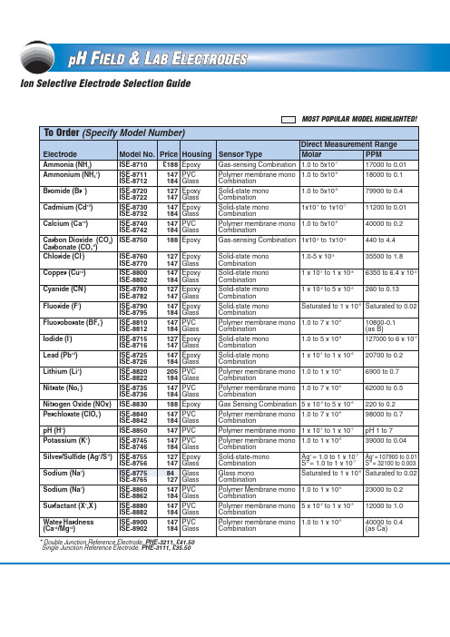
MOST POPULAR MODEL HIGHLIGHTED!Single Junction Reference Electrode, PHE-3111,£35.50Comes with complete operator’s manual.Ordering Examples:ISE-8711,ammonium electrode,£147.ISE-8756,silver/sulfide electrode,£147.C-22PHI-359,£845,bench toppH meter shown smallerthan actual size,see page B-33.C-23CANADA www.omega.ca Laval(Quebec)1-800-TC-OMEGA UNITED KINGDOM Manchester,England0800-488-488GERMANY www.omega.deDeckenpfronn,Germany************FRANCE www.omega.fr 088-466-342BENELUX www.omega.nl 0800-099-33-44UNITED STATES 1-800-TC-OMEGA Stamford,CT.CZECH REPUBLIC www.omegaeng.cz Karviná,Czech Republic596-311-899TemperatureCalibrators, Connectors, General Test and Measurement Instruments, Handheld Instruments for Temperature Measurement, Ice Point References, Indicating Labels,Crayons, Cements and Lacquers, Infrared Temperature Measurement Instruments, Recorders, Relative Humidity Measurement Instruments, PT100 Probes, PT100 Elements,Temperature & Process Meters, Timers and Counters,Temperature and Process Controllers and Power Switching Devices, Thermistor Elements, Probes and Assemblies,Thermocouples, Thermowells and Head and WellAssemblies, Transmitters, Thermocouple Wire, RTD ProbesPressure,Strain and ForceDisplacement Transducers, Dynamic Measurement Force Sensors, Instrumentation for Pressure and StrainMeasurements, Load Cells, Pressure Gauges, PressureReference Section, Pressure Switches, Pressure Transducers,Proximity Transducers, Regulators, Pressure Transmitters,Strain Gauges, Torque Transducers, ValvespH and ConductivityConductivity Instrumentation,Dissolved OxygenInstrumentation,Environmental Instrumentation,pH Electrodes and Instruments,Water and Soil Analysis InstrumentationHeatersBand Heaters,Cartridge Heaters,Circulation Heaters,Comfort Heaters,Controllers,Meters and SwitchingDevices,Flexible Heaters,General Test and Measurement Instruments,Heater Hook-up Wire,Heating Cable Systems,Immersion Heaters,Process Air and Duct,Heaters,Radiant Heaters,Strip Heaters,Tubular HeatersFlow and LevelAir Velocity Indicators,Doppler Flowmeters,LevelMeasurement,Magnetic Flowmeters,Mass Flowmeters,Pitot Tubes,Pumps,Rotameters,Turbine and Paddle Wheel Flowmeters,Ultrasonic Flowmeters,Valves,Variable Area Flowmeters,Vortex Shedding FlowmetersData AcquisitionAuto-Dialers and Alarm Monitoring Systems,Communication Products and Converters,Data Acquisition and Analysis Software,Data LoggersPlug-in Cards,Signal Conditioners,USB,RS232,RS485and Parallel Port Data Acquisition Systems,Wireless Transmitters and Receivers。
USBCAN-I-mini 小型智能 CAN 接口卡产品用户手册说明书
USBCAN-I-mini小型智能CAN 接口卡修订历史目录1. 功能简介 (1)1.1产品概述 (1)1.2参数指标 (1)1.3产品外观 (2)1.4典型应用 (2)2. 设备安装 (3)2.1CAN-bus 连接器 (3)2.2信号指示灯 (3)2.3系统连接 (4)2.3.1CAN 总线连接 (4)2.3.2总线终端电阻 (5)3. 驱动程序安装 (6)3.1在Windows系统下第一次安装驱动程序 (6)3.2检查设备是否安装成功 (7)3.2.1打开WINDOWS设备管理器 (7)3.2.2确认新的设备是否已经成功安装 (8)3.3在Linux下驱动安装 (8)4. 快速使用指南 (9)CANTest基本操作 (9)4.1.1设备类型选择 (9)4.1.2滤波设置 (10)4.1.3启动CAN (11)4.1.4获取设备信息 (12)4.2发送接收实验 (13)4.2.1搭建测试环境 (13)4.2.2打开设备 (13)4.2.3发送数据 (13)4.2.4实时保存与停止保存 (15)4.2.5总线利用率 (15)4.2.6错误信息显示 (16)5. 接口库函数使用方法 (17)5.1在windows下调用动态库的方法 (17)5.1.1VC调用动态库的方法 (17)5.1.2VB调用动态库的方法 (17)5.2接口库函数使用流程 (19)6. 检查和维护 (20)7. 免责声明 (22)附录A CAN报文滤波器设置 (23)A.1单滤波配置 (23)A.2双滤波配置 (25)附录B DB9转OBD接口 (28)B.1功能简介 (28)B.2技术参数 (28)B.3引脚信息 (28)B.3.1DB9接头引脚排列 (28)B.3.2DB9接头引脚描述 (29)B.3.3OBD接头引脚排列 (29)B.3.4OBD接头引脚描述 (30)B.4机械尺寸 (30)附录C SJA1000标准波特率 (31)1. 功能简介1.1 产品概述USBCAN-I-mini智能CAN接口卡是系列USBCAN便携版本,与USBCAN-I单路智能CAN接口卡完全兼容。
西门子 HMI 设备OP 73micro,TP 177micro 操作说明
Internet 上的服务与支持
“服务和支持”提供在线服务,使用户能够获得有关 SIMATIC 产品的其它综合信息。其网址是 "/automation/support":
● 新闻快递提供与您的产品有关的最新信息。 ● 使用我们的“服务和支持”搜索引擎可检索一个大型文档库。 ● 一个用来与全球用户及专家交换信息的论坛。 ● 当前的产品信息、FAQ 及下载。 ● 自动化与驱动产品部门的本地代表 ● 在“服务”标题下可以找到现场服务、维修、备件的相关信息以及更多其它信息
我们已对印刷品中所述内容与硬件和软件的一致性作过检查。然而不排除存在偏差的可能性,因此我们不保证印刷 品中所述内容与硬件和软件完全一致。印刷品中的数据都按规定经过检测,必要的修正值包含在下一版本中。
Siemens AG Automation and Drives Postfach 48 48 90437 NÜRNBERG 德国
注意 表示如果不注意相应的提示,可能会出现不希望的结果或状态。
当出现多个危险等级的情况下,每次总是使用最高等级的警告提示。如果在某个警告提示中带有警告可能导致人身 伤害的警告三角,则可能在该警告提示中另外还附带有可能导致财产损失的警告。
合格的专业人员
仅允许安装和驱动与本文件相关的附属设备或系统。设备或系统的调试和运行仅允许由合格的专业人员进行。本文 件安全技术提示中的合格专业人员是指根据安全技术标准具有从事进行设备、系统和电路的运行,接地和标识资格 的人员。
代表处和分公司 如果您对本手册中所描述的产品有任何疑问,请您与当地最近的 SIEMENS 分支机构的代表处 联系。 可在以下网址找到您的联系伙伴:
"/automation/partner"
HOLLiAS MACS-K 简明选型手册

1.2 HOLLiAS MACS-K 系统结构 ..................................................................................................... 3 1.2.1 系统网络结构组成 ................................................................................................................ 3 1.2.2 系统网、控制网节点功能说明 ............................................................................................ 5 1.2.3 系统环境要求 ........................................................................................................................ 6 1.2.4 性能指标 ................................................................................................................................ 6 1.2.5 硬件结构 ................................................................................................................................ 9 1.2.6 硬件选型 .............................................................................................................................. 13 1.2.7 选型注意事项 ...................................................................................................................... 19 第2章 2.1 2.2 2.3 第3章 3.1 控制器模块 ............................................................................................................................... 21 概述 ........................................................................................................................................... 21 K-CU01 控制器 ............................................................................................................................ 22 K-CU02 控制器 ............................................................................................................................ 23 常用 I/O 模块选型 ................................................................................................................... 24 概述 ........................................................................................................................................... 24
赫斯曼交换机产品介绍

RS30
-
08
02
T1
O6
S D A P H C
01.0
2,提供/支持端口数量
百兆
04 (only RS 20) 08
提供4个100M端口 (00 for RS 40) 提供/支持8个100M端口
09
16 17
提供/支持9个100M端口
提供/支持16个100M端口 提供/支持17个100M端口
• 千兆以太网 (1000BASE SX) • M-SFP SX/LC 550m(275m) with 50u(62.5u) Multimode fibre • M-SFP LX/LC 20km with 9u Singlemode fibre • M-SFP LH/LC 70km with 9u Singlemode fibre • M-SFP LH+/LC 120km with 9u Singlemode fibre
E
5,供电类型
D A C
Rail 12/24 V/48 V DC (9.6 – 60V) and 24 VAC (18 – 30 V) 工业12/24/48V直流供电或24V交流供电 24 V (18-32) V DC FOR MICE 24V直流供电(仅限MICE系列)
32-60 V DC MICE 32-60直流供电(仅限MICE系列)SFP FE & GE
9.
10/100/1000TX
MS系列
FE
MS20-0800xx
MS20-1600xx
扩展底板 MB-2T
FE+GE
MS30-0802xx
MS30-1602xx
物理连接样式 MS20-0800 2 个百兆模块插槽(不可扩展底板)
- 1、下载文档前请自行甄别文档内容的完整性,平台不提供额外的编辑、内容补充、找答案等附加服务。
- 2、"仅部分预览"的文档,不可在线预览部分如存在完整性等问题,可反馈申请退款(可完整预览的文档不适用该条件!)。
- 3、如文档侵犯您的权益,请联系客服反馈,我们会尽快为您处理(人工客服工作时间:9:00-18:30)。
/
邦定胶
734
单组份,蜂蜜状流动性较好,热固化,灌封粘接涂抹
/
736
膏状不流动,热固化,粘接力强,涂刷保密
/
737-C
膏状不流动,低温固化,粘接金属,塑料等材质
/
739
蜂蜜状能流动,热固化,粘接强度高,保密性好
/
SG160
白色膏状不干,涂抹方便,导热性好
/
SG260
白色膏状微塌不干,涂抹方便,导热性好
20:1
RTVS21 双组份浅红色,极高导热率,流动性较好
1:1
RTVS287 对灌封构件等连续拔插多次依然保持自动修复性,高频性好
1:1
RTVS605 双组份高透明,操作时间长,粘度低,韧性很好
10:1
RTVS901 双组份高透明,透光率高,可拆性好
1:1
RTVS6100 双组份高透明,粘度低,凝固表面带粘性,极软
10:1
RTVS12 双组份灰黑色,粘度低,凝固后弹性,多数基材附着力好
1:1
RTVS27 双组份灰黑/白可选,粘度低,凝固后弹性,导热性能好
1:1
RTVS27LV 双组份黑色,粘度低,高绝缘,带粘性,优异介电常数
1:1
RTVS28 双组份深灰,粘度低,能渗透进微小缝隙,介电常数低
1:1
RTVS29 双组份流动性好,模块电源灌封散热,绝缘,高压模块灌封
1:1
RTVS6100-2 双组份高透明凝胶,自修复性,耐低温优异
1:1Leabharlann RTVS6103 半导体IGBT、传感器集成模块等封装保护IC 芯片灌封,耐高压好 1:1
711
双组份黄色透明,防水密封性能优异,电路板防水
1:1
712 聚氨酯灌
封胶 713 715
双组份黑色,粘度低,固化速度快,防潮性佳 双组份黑色,硬度可调,操作时间长,韧性优异,导热好 双组份黑色,1-2小时表干,韧性优异,导热好
RTVS301 黑/白/半透明可选,固定,粘接,透明型可以用作涂覆
/
RTVS302 15-25分钟表干,流动性好,单组份,薄层凝固
/
RTVS302L 黑色流体,涂敷之后可以快速流动/填充/自流平
/
RTVS303 半透明半流体,10-15分钟表干,PVC/橡胶/铝/玻璃粘接
/
RTVS306 白色流体,15-30分钟表干,ABS/橡胶/铜材/不锈钢粘接
2:1
3019
双组份黑色,热变形温度高达180度,导热性好
100:8
6213FR&13C 双组份黑色,导热性优异,粘度高耐高温
100:3-5
6213FR&11B 双组份黑色,导热性优异,流动性较好操作时间长
100:10
6218
双组份灰色,导热性优异,操作时间长,粘接力强
100:10
RTVS11 双组份黑色,粘度低,凝固后弹性,附着力好
/
SG861
灰白色膏状不干,涂抹方便,导热性优异
/
导热硅脂/ 散热膏
SG7620
灰色膏状不干,粘贴性好,油离度低
/
SG7625 灰色膏状不干,涂抹方便,油离度低,导热优异
/
SG7630 灰色膏状不干,粘贴性好,极好的散热性
/
SG7650 白色膏状半流趟,耐高温性能优异,不干
/
5011灰色 天然粘性,容易装配,多种发热元件散热粘贴
/
RTVS307 白色膏体,10分钟表干,功率元件粘接,导热优异
/
密封胶
RTVS307L 白色半流体,10分钟表干,功率元件粘接,导热优异
/
RTVS308H 黑色膏体,30-40分钟表干,耐高温,电熨斗,烤箱密封粘接 /
RTVS312 半透明流淌,20-25分钟表干,粘接硅胶/ABS/亚克力/玻纤
/
流动性好,耐酸碱腐蚀,耐溶剂性能佳
100:12
141
流动性好,耐溶剂性能优异,附着力强,保密灌封
5:1
142SW
流动性优异,凝固后柔性佳,多种材料都有良好的附着力
5:1
776FR
双组份黑白可选,2-3小时表干,导热优异,热变形温度160
8:1
环氧树脂 985FR
双组份黑白可选,可操作时间长,耐高温高压
/
3210
UV光固化,透明度高,硬度好,不收缩
/
3212
琥珀色,PCB电路板元器件、排线、焊点的披覆保护
1:1
RTVS41 双组份灰色,流动性好,室温1-2小时表干
1:1
有机硅灌 RTVS42 双组份灰色,流动性好,凝固韧性较好,指甲不易抠烂
1:1
封胶 RTVS187 双组份灰黑色,粘度低,导热性能优异,耐高温280度
1:1
RTVS189 双组份灰色,较稠,导热性能优异
1:1
RTVS49 双组份红色,极高导热率,流动性较好
HASUNCAST常用产品选择指南
型号
产品特点
重量配比
112FR
黑白可选,粘度低,固化速度快,通用电路板灌封保护
5:1
122
双组份黑色,流动性好,操作时间长,需要加热凝固
3:1
126FR
配比简单,固化速度较快,粘接多种金属和塑料,气密性好
1:1
128FR
粘度适中,带柔性可克服应力,密封性极好
1:1
129
/
5012蓝色 天然粘性,容易装配,多种发热元件散热粘贴
/
导热硅胶 片
5013蓝色
天然粘性,容易装配,多种发热元件散热粘贴
/
5014灰色 天然粘性,容易装配,多种发热元件散热粘贴
/
5015灰色 天然粘性,容易装配,多种发热元件散热粘贴
/
FA-8
常温1-2小时表干,F级绝缘,线圈浸渍
/
三防漆
303coating 半透明流淌,15-20分钟表干,H级耐高温三防硅胶,电路板涂刷 /
5:1
灌封胶 3010
双组份透明,操作时间长,粘度低
2:1
3013
双组份高透明,操作时间长,粘度低,耐高温性能优异
3:1
3016
双组份透明,柔性,可操作时间长,流动性好,配比简单
1:1
3016LV 双组份透明,柔性,可操作时间长,流动性好
3:1
3018
双组份茶色透明,流动性好,凝固快,热变形温度120度
RTVS313 半透明膏状,10-15分钟表干,粘接PC/PVC/硅胶/不锈钢
/
RTVS182 灰色膏状半流趟,120度1小时凝固,高温部件粘接固定
1:1
RTVS185 单组份,150度1小时深层凝固,功率器件,散热片粘接固定
/
3200
玻璃金属水晶等小面积粘接,展柜粘接
/
3201
大面积玻璃,水晶影像,图片等粘接
5:1 6-8:1 8:1
718
双组份黑色,流动性好,常温1-2小时表干,韧性优异,导热好 6:1
118
膏状不流动,常温1-3小时固化,粘接力强
5:1
148
铁氧体,磁铁,钢材,玻璃,电镀金属件粘接固定
单组份
730
热固化,金属轴套粘接,修复,高温部位填充灌封
2:1
732
加热器封口,高温部位填充粘接,火花塞组装固定