流量检测系统说明书(正式版)
海瑞思 HC 系列流量检测仪说明书

流量检测仪说明书手册修订前言亲爱的客户:感谢您信赖我们的品牌,购买海瑞思流量检测仪,此仪器被设计的尽可能实用和稳定,我们深信它在多年的使用期间,能够带给您非常满意的体验。
为了更好的操作仪器,请仔细阅读说明书。
本说明书介绍的是海瑞思HC系列流量检测仪的安装、设置、产品功能、操作方法、保养、维修和操作注意事项等。
使用前请仔细阅读本说明书,并妥善保管。
安全注意事项本说明书记录了如何正确安全的使用流量检测仪的方法,并阐述了防止对操作者本人和他人造成危害及财产损失的内容。
不可进行本操作说明书记载以外的操作。
[标识说明]目录第一章、准备和安装 (1)1.开箱 (1)1.1准备工作 (1)1.2附件 (1)2.仪器组成 (1)2.1仪器正面构成 (1)2.2仪器背面构成 (2)3.仪器安装与连接 (2)3.1流量检测仪安装环境 (2)3.2仪器气源/电源连接 (2)3.3工装夹具与仪器的连接 (2)3.4控制接口的说明 (3)第二章、仪器界面操作说明 (6)1.总览 (6)1.1开机界面说明 (6)2.用户登录 (6)2.1如何进行用户登录? (6)2.2如何修改密码? (8)2.3如何注销用户? (9)2.4新建用户 (9)3.测前设置 (9)3.1显示方式 (10)3.2启动方式 (11)3.3语言选择 (12)3.4单位选择 (12)3.5精度选择 (13)3.6当前压力 (14)3.7仪表回零 (14)3.8正压 (14)3.9负压 (14)4.程序参数 (14)4.1测试类型选择 (15)4.2测试方法选择 (16)4.3附加功能 (16)4.4测试时间参数 (17)4.5测试压力参数 (17)4.6外部输出状态 (18)4.7上方按钮说明 (18)4.8下方按钮说明 (20)5.系统设置 (21)5.1如何进入系统设置? (21)5.2输出 (22)5.3条码扫描参数 (22)5.4其他参数设置 (22)5.5通信状态 (22)5.6高级 (22)6.测试界面 (25)6.1测试界面 (25)7.历史记录 (26)7.条码扫描 (28)8.远程控制 (29)8.1 485modbus站号 (29)8.2 232modbus站号 (29)8.3结果上传 (29)8.4通信485串口/通信方式网口 (29)8.5 MES控制无效/MES控制有效 (29)8.6 IP地址 (30)9.工厂模式 (30)第三章、维护和保养 (31)1关于仪器保养 (31)1.1每天进行检测项目 (31)2.1 测试中NG多发时 (33)2.2 历史记录无法导出 (34)2.3仪器测试结果与实际泡水实验结果不对应 (34)第一章、准备和安装1.开箱1.1准备工作a)稳定且清洁的压缩气体,气压0.4Mpa-0.8Mpa;b)平稳并足够可靠的工作台;c)稳定且无泄漏的工装夹具;d)电源要求AC 220V(±15%)、50HZ;e)插好仪器的电源线,进出气气管、仪器与工装通讯的25PIN排线;连接方式见图1-3;1.2附件2.仪器组成2.1仪器正面构成图1-1 防滑脚垫X4橡胶提手停止按钮/NG指示灯蜂鸣器开始按钮/OK指示灯操作屏幕2.2仪器背面构成2.2.1背面构成A图1-23.仪器安装与连接3.1流量检测仪安装环境a) 仪器工作环境温度,尽量保持在26C °±1°;b) 仪器摆放避开门口、通风口、空调口等;c) 仪器摆放桌面要稳定可靠,仪器周边不得摆放杂物;3.2仪器气源/电源连接a) 如图1-4所示,首先将仪器摆放到平整且稳定的桌面,将电源线一端插进仪器电源接口,另一端插入220V/50HZ 单相电源插座上;b) 将φ8的气管一端接到仪器进气接口,另一端接到工厂气源上; c) 将测试接口的气管接到工件或者模具上; d) 打开电源开关,等待2-3秒,仪器启动完成;3.3工装夹具与仪器的连接进气接口 电源接口电源开关 仪器锁RS232/485接口 25PIN I/O 接口测试口B测试口A 铭牌网络接口 USB 接口图1-3图1-4工装与仪器连接步骤:a) 如图1-4,经过过滤后的工厂气源,分为两路,一路供给工装,一路供给仪器; b) 工装和仪器都是采用φ8的气管连接;c) 将仪器上φ4的出气管,连接到模具进气口; d) 用工装上25P 的排线连接到仪器上; e) 工装与仪器连接完成;3.4控制接口的说明a) 以太网接口:用于连接电脑(选配);接φ8的进气管 φ4测试管,连接模具 25PINO I/O 连接线 φ4测试气管 φ8进气管 电源线b)USB接口:用于导出历史数据或者安装扫码枪;c)RS485接口:标准通信接口,可连接电脑,需要通讯协议,请联系销售工程师;d)25PIN I/O接口:海瑞思专用控制数据接口;外部输出:默认是24V直流输出,输出电流最大0.5A。
流量检测装置说明书

流量检测装置设计说明书一、装置需求:1. 100点流量差压信号的采集。
用键盘输入流量系数,输入时可显示;2.范围0-1000l/min,采集周期0.5s,信号4-20mA,分辨力0.1%;3.要求运用数字滤波(方法自选);4.计算瞬时流量(l/min)、累计流量(m3/h),并显示;5.操作人员可随时修改流量系数和切换显示内容(瞬时/累计流量)。
二、设计说明书要求:1.系统构成框图及构成说明,包括主要部件的选型及依据;2.DSP与A/D转换芯片连接的电原理图;3.程序框图,包括主要流程;4.采集、数字滤波、流量计算程序清单。
三、差压式流量计基本理论1.节流装置工作原理差压式流量计是根据伯努力方程和流体连续性原理用差压法测量流量的,其节流装置工作原理如图1所示,在横截面H处:流体的平均流速是v1,密度是ρ1,横截面积是A1;在横截面L处:流体的平均流速是v2,密度是ρ2,横截面积是A2。
图1 差压流量计工作原理图根据流体流动连续性原理有如下关系式:v1·A1·ρ1=v2·A2·ρ 2 (1)如果流体是液体,可认为在收缩前、后其密度不变:ρ1=ρ2=ρ(2)根据瞬时流量的定义,即单位时间内流体流经管道或明渠某横截面的数量,所以液体的体积瞬时流量:2211A v A v q v ⋅=⋅= (3)根据伯努利方程(能量守恒定律),在水平管道上Z1=Z2,则有如下关系式:2222222111v P v P ρρ+=+ (4)应用伯努利方程和流动连续性原理,在两个横截面上压力差则有如下关系式:)(2212221v v P P P -=-=∆ρ (5)将(3)代入(5)式,并整理,则得:22212])(1[2v A A P -=∆ρ(6)由于421D A ⋅=π, 422d A ⋅=π, 定义直径比Dd =β, 其中d 为工作状况下节流件的等效开孔直径,D 为管道直径,则得到:2224)1(2A q P v βρ-=∆ (7) 这样可推导出以下的理论流量公式:1242411ρπβPd q v ∆⋅-= (8)又由于流量系数C 的定义是:C= 实际流量/理论流量,可得出节流式差压流量计普遍适用的测量体积流量的实际流量公式:ρπβεPd C q v ∆⋅-⋅=24124 (9)其中,ε为被测介质的可膨胀性系数:对于液体=1; 对气体、蒸气等可压缩流体<1 。
E+H 电磁流量计promag 10W中文说明书
KA00032D/06/ZH/14.1171154561简明操作指南Proline Promag 10电磁流量测量系统6本《简明操作指南》不能替代供货范围中的《操作手册》。
详细信息请参考《操作手册》以及随附CD 上的其他文档。
完整的设备文档包括:•《简明操作指南》•与仪表型号相符的相关文档:–《操作手册》和《仪表功能描述》–防爆证书及安全证书–安装指南 — 与仪表型号相关(例如防爆证书、压力设备规程等)–其他相关信息Proline Promag 10目录1 安全指南. . . . . . . . . . . . . . . . . . . . . . . . . . . . . . . . . . . . . . . . . . . 31.1 用途 . . . . . . . . . . . . . . . . . . . . . . . . . . . . . . . . . . . . . . . . . . . . . . . . . . . . . . . . . . . . . . . 31.2 安装、调试和操作 . . . . . . . . . . . . . . . . . . . . . . . . . . . . . . . . . . . . . . . . . . . . . . . . . . . 31.3 操作安全 . . . . . . . . . . . . . . . . . . . . . . . . . . . . . . . . . . . . . . . . . . . . . . . . . . . . . . . . . . . 31.4 安全图标 . . . . . . . . . . . . . . . . . . . . . . . . . . . . . . . . . . . . . . . . . . . . . . . . . . . . . . . . . . . 52 安装 . . . . . . . . . . . . . . . . . . . . . . . . . . . . . . . . . . . . . . . . . . . . . . . 62.1 运往测量点 . . . . . . . . . . . . . . . . . . . . . . . . . . . . . . . . . . . . . . . . . . . . . . . . . . . . . . . . . 62.2 安装条件 . . . . . . . . . . . . . . . . . . . . . . . . . . . . . . . . . . . . . . . . . . . . . . . . . . . . . . . . . . . 72.3 Promag L传感器的安装 . . . . . . . . . . . . . . . . . . . . . . . . . . . . . . . . . . . . . . . . . . . . . . 122.4 Promag W传感器的安装 . . . . . . . . . . . . . . . . . . . . . . . . . . . . . . . . . . . . . . . . . . . . . 172.5 Promag P传感器的安装 . . . . . . . . . . . . . . . . . . . . . . . . . . . . . . . . . . . . . . . . . . . . . . 232.6 Promag H传感器的安装 . . . . . . . . . . . . . . . . . . . . . . . . . . . . . . . . . . . . . . . . . . . . . . 272.7 变送器外壳的安装 . . . . . . . . . . . . . . . . . . . . . . . . . . . . . . . . . . . . . . . . . . . . . . . . . . 282.8 安装后检查 . . . . . . . . . . . . . . . . . . . . . . . . . . . . . . . . . . . . . . . . . . . . . . . . . . . . . . . 303 接线 . . . . . . . . . . . . . . . . . . . . . . . . . . . . . . . . . . . . . . . . . . . . . . 313.1 不同外壳类型的仪表连接 . . . . . . . . . . . . . . . . . . . . . . . . . . . . . . . . . . . . . . . . . . . . 323.2 分体式仪表的电缆连接 . . . . . . . . . . . . . . . . . . . . . . . . . . . . . . . . . . . . . . . . . . . . . . 333.3 电势平衡 . . . . . . . . . . . . . . . . . . . . . . . . . . . . . . . . . . . . . . . . . . . . . . . . . . . . . . . . . . 363.4 防护等级 . . . . . . . . . . . . . . . . . . . . . . . . . . . . . . . . . . . . . . . . . . . . . . . . . . . . . . . . . . 373.5 连接后检查 . . . . . . . . . . . . . . . . . . . . . . . . . . . . . . . . . . . . . . . . . . . . . . . . . . . . . . . . 374 调试 . . . . . . . . . . . . . . . . . . . . . . . . . . . . . . . . . . . . . . . . . . . . . . 384.1 开启测量设备 . . . . . . . . . . . . . . . . . . . . . . . . . . . . . . . . . . . . . . . . . . . . . . . . . . . . . . 384.2 运行 . . . . . . . . . . . . . . . . . . . . . . . . . . . . . . . . . . . . . . . . . . . . . . . . . . . . . . . . . . . . . . 394.3 浏览功能表 . . . . . . . . . . . . . . . . . . . . . . . . . . . . . . . . . . . . . . . . . . . . . . . . . . . . . . . . 404.4 调试期间需设置的仪表功能 . . . . . . . . . . . . . . . . . . . . . . . . . . . . . . . . . . . . . . . . . . 414.5 故障检测 . . . . . . . . . . . . . . . . . . . . . . . . . . . . . . . . . . . . . . . . . . . . . . . . . . . . . . . . . . 42 2Endress+HauserProline Promag 10安全指南1安全指南1.1用途•本测量设备仅用于测量密闭管道中导电介质的流量。
FlowJam S 液体流量检测仪操作指南说明书

FlowJam S ow detection owJam Sow detectionCONTENTS Page1. Function . . . . . . . . . . . . . . . . . . . . . . . . . . . . . . . . . . . . . . . . . . . . . . . . . . . . . . . . . . . . . . . . . . . . . . . . . . 32. Safety . . . . . . . . . . . . . . . . . . . . . . . . . . . . . . . . . . . . . .. . . . . . . . . . . . . . . . . . . . . .. . . . . . . . . . . . . . . . . . 43. Mounting and installation . . . . . . . . . . . . . . . . . . . . . . . .. . . . . . . . . . . . . . . . . . . . . .. . . . . . . . . . . . . . . 5 3.1 Basic remarks . . . . . . . . . . . . . . . . . . . . . . . . . . . . . . . . . . . . . . . . . . .. . . . . . . . . . . . . . . . . . . . . . . . . . 5 3.2 Installation of the sensor in general . . . . . . . . . . . . . . . . . . . . . . . . . . . . . . . . . . . . . . . . . . .. . . . . . .53.3 Installation of the sensor on conveyor belts . . . . . . . . . . . . . . . . . . . . . . . . . . . . . . . . . . . . . . . . . . . . 64. Electrical connection . . . . . . . . . . . . . . . . . . . . . . . . . . . . . . . . . . . . . . . . . . . . . . . . .. . . . . . . . . . . . . . . . . 75. Commissioning . . . . . . . . . . . . . . . . . . . . . . . . . . . . . . . . . . . . . . . . . . . . . . . . . . . . . . . . . . . . . . . . . . . . . . . . 86. Troubleshooting . . . . . . . . . . . . . . . . . . . . . . . . . . . . . . . . . . . . . . . . . . . . . . . . . . . . . . . . . . . . . . . . . . . . . . . 97. Notice . . . . . . . . . . . . . . . . . . . . . . . . . . . . . . . . . . . . . . . . . . . . . . . . . . . . . . . . . . . . . . . . . . . . . . . . . . . . . . . 98. Declaration of conformity . . . . . . . . . . . . . . . . . . . . . . . . . . . . . . . . . . . . . . . . . . . . . . . . . . . . . . . . . . . . . . 109. Technical data . . . . . . . . . . . . . . . . . . . . . . . . . . . . . . . . . . . . . . . . . . . . . . . . . . . . . . . . . . . . . . . . . . . . . . . 101. FunctionThe radar flow detector FlowJam S indicates the flow of bulk materials which moves through the detection range (fig. 1) at a minimal required speed of 0.1 m/s.The detection is executed by evaluating the Doppler’s effect, thus independent of the flow direction.The material flow, which can be in metallic or non-metallic tubes, ducts, free fall distances and discharge points, is indicated by relays.The sensor distinguishes between two conditions: •material flow•material jam or standstill.FlowJam S can be adapted to extreme process conditions like high temperature by a separating flange equipped with a window especially for microwaves.Fig. 1: Detection range103ø 5230G 1 1/2"Fig. 2: Dimensional drawing2. SafetyThe sensor FlowJam S was designed, built and tested to be safe and was shipped in safe condition. Nevertheless persons or objects may be endangered by components of the system if these are operated in an inexpert manner. Therefore the operational instructions must be read completely and the safety notes must be followed.In case of inexpert or irregular use, the manufacturer will refuse any liability or guarantee.2.1 Regular use•Only original spare parts and accessories of SWR engineering must be used.2.2 Identification of dangers•Possible dangers when using the sensor are marked in the operating instructions.2.3 Operational safety•The sensor must be installed by trained and authorised personnel only.•In case of maintenance-work on the pipe or on components of the FlowJam S-sensor, make sure that the piping is in unpressurized condition.•Switch off the power supply for all maintenance, cleaning or inspection works on the tubes or on components of the FlowJam S.•Before hot work the sensor must be removed from the installation place.•The components and electrical connections must be checked for damages regularly. If a damage is found, it is to be repaired before further operation of the instruments.2.4 T echnical progress•The manufacturer reserves the right to adapt technical data to the technical progress without particular advance notice. If you have any questions, SWR engineering will be pleased to inform you on possiblechanges and extensions of the operating instructions.3. Mounting and installation3.1 Basic remarksFlowJam S has to be mounted at an angle between 45° and 90° to the flow direction of the bulk material.Be careful to mount the sensor in an absolutely vibration-free area and that no parts within the detection range are moving, because this might be detected as a material flow.Moving parts within the area of detection have to be screened.3.2 Installation of the sensor in generalThe installation of the sensor depends on the conditions of the site, thus the sensor can be •screwed directly into an existing thread type G 1 1/2“ (fig. 3) •fixed by a flange (fig. 4)•mounted by means of a pipe clamp (fig. 5)Before installation, make sure that neither the medium temperature nor the pressure within the piping or the container require additional measures like e. g. the mounting of a separating flange pervious for microwaves (fig. 6).When used with non-conductive tubes, detection is carried out via the side of the tube. It is not necessary to make a separate hole into the tube.Fig. 3: Thread mountingFig. 4: Flange mountingFig. 5: Mounting with pipe clampFig. 6: Mounting with separating flange3.3 Installation of the sensor on conveyor beltsIf possible, the installation on conveyor belts is to be executed in the area of the discharge point.If the installation is above a conveyor belt, then the FlowJam S has to be installed at an angle of approx. 70 - 80° (fig. 7), in order to use the changing surface profile of the bulk material flow.Based on the formula for the doppler frequency, the following relation can be pointed on.D f = 2 (V* cos α/C) fo (Fig. 8)V = resulting speedD f = frequency shiftfo = transmitted frequencyα= angle of the sensor to flow direction at the bulk materialAngle approx. 90°; mainly the speed of the change of the damping height is measured.Angle approx. 0°; mainly the material speed is measured.Fig. 7: Installation above conveyor belt4. Electrical connectionThe connection of the sensor and transmitter has to be carried out according to fig. 8 and 9.A maximum length of 300 m cable between sensor and transmitter should not be exceeded.Fig. 8: Wiring diagram for sensor (standard-version: with jumper / high-version: without jumper)Fig. 9: Wiring diagram for DIN Rail electronicFig. 10: Wiring of sensor and DIN Rail electronic5. CommissioningAll operational controls required for the alignment are shown in fig. 11.Control elements:• LED 1: Signal strength • LED 2: Material flow • S1: Switching betweenworking current / closed current • S2: Coarse adjustment of sensitivity • P1: Threshold level • P2: Delay timeSwitch S1The position of switch S1 determines, whether the relay is attracted up or released at material flow.Position ”2” (off) causes alarm in case of material flow: • material flow - relay is attracted- contacts 7 + 8 closed • no material flow - relay is released- contacts 6 + 7 closed Position ”1” (on) causes alarm when there is no material flow: • material flow - relay is released- contacts 6 + 7 closed • no material flow - relay is attracted- contacts 7 + 8 closedLED 1The LED 1 (red) lightning shows the signal strength by its luminosity; that is, no lightning if no reception signal (no material flow, no vibrations, etc.), weak lightning if low and strong lightning if intense reception signal.LED 2The LED 2 (green) lights always up, if material flow is detected; this display is independent of the positionof the switch S1.678Fig. 11: Position of control elementsAdjustment of sensitivityHereto use switch S2, potentiometer P1 and potentiometer P2.The control elements are in the following positions at the delivery (this basis is crucial for thecommissioning):•P1 (fine adjustment of sensitivity): at the left lay, thus insensitive•S2 (coarse adjustment of sensitivity): switch at (on), thus relatively insensitive•Jumper on sensor electronic (coarse adjustment of sensitivity): put on, thus relatively insensitive•P2 (delay time): at the left lay, thus minimal delay of 250 msNow start your machine in order to guarantee material flow. In consequence the LED 1 must glow. If the LED 1 doesn’t glow, then the switch S2 has to be set on (off). If there is still no lightning, then either the sensor has to be aligned differently, and/or the jumper has to be pulled out.Now choose the position of the switch S1 accordingly, if the relay has to be turned (on) or (off) at material flow.Enhance the sensitivity so long until the LED 2 glows and the relay switches (off) or (on).If you interrupt the material flow, both LED lightning must go out, whereas the LED 2 goes out at the latest if the delay time ends.Finally, you can adjust the delay time according to your requirements with potentiometer P2 in the range of 250 ms ... 15 s.6. TroubleshootingIf LED 1 does not light up even at the largest possible amplification, the following points must be checked:•properties of the material flow (see e. g. fig. 7)•positioning of the installation•distance between the sensor and the material flowIf LED 1 lights up without an existing material flow and with minimal amplification adjusted on S2 and P1, it is very likely that the sensor detects the motion of something else or vibrations.Attention: Does the LED 1 lights up continuously, then either there is no connection between sensor and DIN Rail electronic, or the sensor is broken!7. Notice•Avoidance of reflection by vibration or moving line parts•Setting of the amplification by potentiometer P1 until just of the switching threshold (LED 2 glows)9. T echnical dataSensorPower supply12 V DC powered by transmitter Power consumption approx. 1.5 WHousingStainless steel 1.4571Protection system IP 65Process temperature- 20 ... + 80 °C (standard)- 20 ... + 220 °C (with process-adapter) - 20 ... + 1000 °C (with ceramic-flange)Ambient temperature - 20 ... + 60 °CWorking pressure max. 1 bar (standard) / max. 20 bar (with process-adapter)Detection range0 ... 2 m (dependent on application)Required material speed for detection min. 0.1 m/sMeasuring frequency K-Band 24.125 GHz / ± 100 MHz Transmitting power max. 5 mWDimensions Housing: L 103 mm / Ø 52 mm / Thread: L 30 mm / Ø G 1½Weightapprox. 560 g(A l l r i g h t s r e s e r v e d .)8. Declaration of conformityConforms to the following Product Specifications:Number: 89/336/EEC Text: Electromagnetic CompatibilityThe product herewith complies to requirements of the EMC directive 89/336/EEC:Reference No. Date Reference No. Date DIN EN 55011 2007 DIN EN 61000-4-3 1997DIN EN 61000-1 DIN EN 61000-6-1 2002DIN EN 61000-3-2 2001 DIN EN 61000-6-2 2000DIN EN 61000-3-32001DIN EN 61000-6-32002Transmitter Power supply24 V DC ± 10 %Power consumption approx. 3.5 WRelay• Voltage • Current • Powermax. 110 V AC max. 1 A 60 WFall-delay time 250 ms ... 15 s (continuously adjustable)Weightapprox. 172 gSWR engineering Messtechnik GmbHGutedelstraße 31 · 79418 Schliengen (Germany)Fon +49 7635 827248-0 · Fax +49 7635 827248-48 · Superior with Solids。
PROline Promag 50 53W 电磁流量测量系统 说明书
测量系统
测量系统由一个变送器和一个传感器组成 可以使用两种形式: • 一体化:变送器和传感器组成单机 • 分体型:变送器和传感器分别安装 变送器: • promag 50(用户接口有操作按钮,两行显示) • promag 53(“轻触控制”不需要打开外壳,四行显示) 传感器: • promag W(DIN 25… 2000)
小流量截止 电隔离
小流量截止的转换点可选 所有输入、输出和电源电路相互电隔离
Endress+Hauser
5
Promag 50/53 W
电源
测量装置电气连接
变送器的接线,电缆截面积:最大 2.5 mm2 上:现场外壳 下:墙装外壳 电源电缆:85 …260 V AC,L+直流 端子号 1: AC 线电压, DC 正电源 L+ 端子号 2: AC 零, DC 负电压 Lb 信号电缆:端子号 20 – 27,见第 5 页 c 接地端子:用于保护导体 d 接地端子:信号电缆屏蔽 e 维修连接器,用于连接维修接口 FXA 193 (FieldCheck, ToF Tool现场工具包) f 接线盒盖 g 定位夹
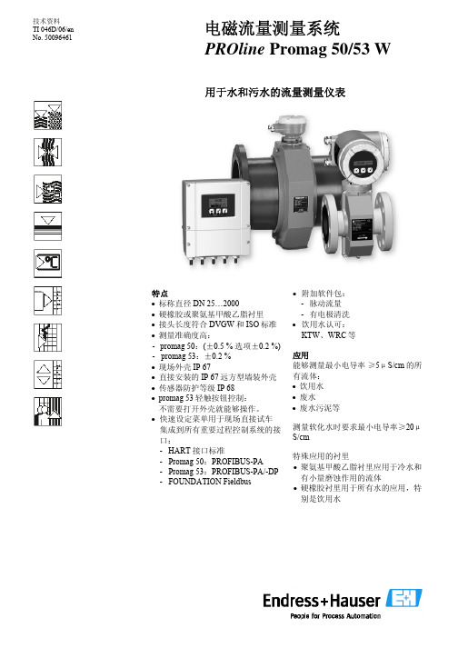
技术资料 TI 046D/06/en No. 500 Promag 50/53 W
用于水和污水的流量测量仪表
特点 • 标称直径 DN 25…2000 • 硬橡胶或聚氨基甲酸乙脂衬里 • 接头长度符合 DVGW 和 ISO 标准 • 测量准确度高: - promag 50:(±0.5 % 选项±0.2 %) - promag 53:±0.2 % • 现场外壳 IP 67 • 直接安装的 IP 67 远方型墙装外壳 • 传感器防护等级 IP 68 • promag 53 轻触按钮控制: 不需要打开外壳就能够操作。 • 快速设定菜单用于现场直接试车 集成到所有重要过程控制系统的接 口: - HART 接口标准 - Promag 50:PROFIBUS-PA - Promag 53:PROFIBUS-PA/-DP - FOUNDATION Fieldbus
流量检测仪使用说明书

Flo-Tech, PFM6 流量压力检测仪使用说明书流量压力检测仪的使用要领1. 检测仪各部名称(图1)涡轮流量计各部名称(图2)2. Flo-tech检测仪参数* 为现用检测仪(1) 检测仪使用要点本检测仪操作简单,不需要特殊练习,就可以立刻使用。
为了正确的判断试验结果,有必要事先了解测试对象的液压系统和各液压执行部件,掌握必要的资料,比如:操作压力、流量、溢流阀设定压力、液压泵的最高输出压力、液压泵的性能曲线等。
①液压软管的连接检测仪如上表所示有三种机型,其软管的连接分两种类型a、PFM6-50、PFM6-85为1英寸的PT内螺纹。
b、PFM6-200上附有1英寸PT螺纹的连接器。
90°的管接头、T型管接头、阀等距离检测仪的输入端最好在30cm以上,因为这些部件将会给流体的测量带来误差。
软管的另一侧(与被测机器连接侧)通常与连接检测仪一侧为相同连接螺母,所以当管径或螺纹不同时,请利用转接器。
②操作要领检测仪的操作是简单的,但误操作将会给检测仪或被测试机器、回路带来不良影响。
使用者在使用前请读熟本使用说明书,避免误操作,以提高测试效率。
a、转换开关通常在中央位置(OFF)测试流量时请放在(FLOW)档位测试油温时请放在(TEMP)档位测试结束后,请勿必将开关拨回到OFF位置。
干电池使用过期电压下降时,仪表(流量、温度计上的冒号:)将发生闪烁。
此时,请更换干电池。
b、认真确认软管是否已正确无误地连接在检测仪的输入、输出端。
检测仪可以并列接入高压侧,但流向若是接反则不能测量正确的流量。
c、液压回路动作前,应将加载阀反时针方向旋转打开。
d、加载阀可以用手简单地进行操作,在加压和卸压时,请缓慢地进行操作。
e、液压回路动作停止之前,要将加载阀打开,确认压力是否已降到零。
在进行多项压力测试时,每一次测试结束,也都应该将加载阀先打开,然后进行下一个项目的测试。
f、安全圆片是保护检测仪和液压机器的,测试时,请密切注意压力表的读数,使之不要超过回路的最高压力。
流量监测仪产品说明书
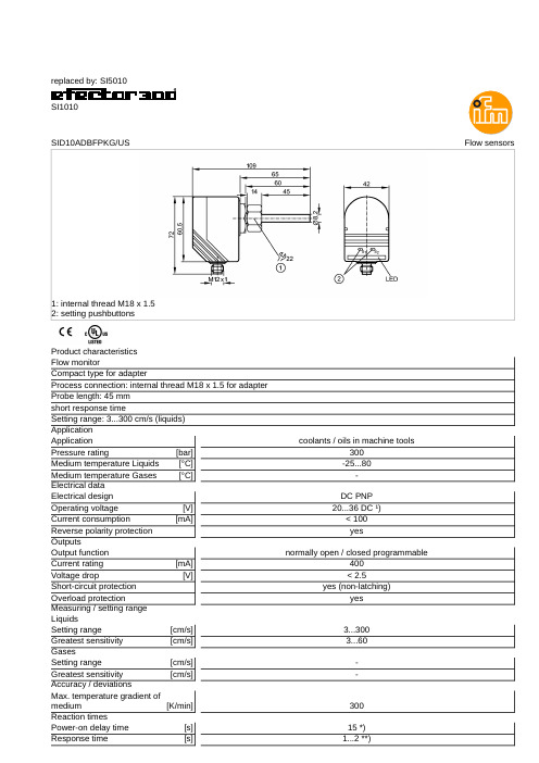
replaced by:SI5010SI1010Flow sensorsSID10ADBFPKG/US1:internal thread M18x 1.52:setting pushbuttonsProduct characteristics Flow monitorCompact type for adapterProcess connection:internal thread M18x 1.5for adapter Probe length:45mm short response timeSetting range:3...300cm/s (liquids)Application coolants /oils in machine toolsApplication 300Pressure rating [bar]-25 (80)Medium temperature Liquids [°C]-Medium temperature Gases [°C]Electrical data DC PNP Electrical design 20...36DC ¹)Operating voltage [V]<100Current consumption [mA]yesReverse polarity protection Outputsnormally open /closed programmableOutput function 400Current rating [mA]<2.5Voltage drop [V]yes (non-latching)Short-circuit protection yesOverload protectionMeasuring /setting range Liquids3...300Setting range [cm/s] 3...60Greatest sensitivity [cm/s]Gases-Setting range [cm/s]-Greatest sensitivity [cm/s]Accuracy /deviations300Max.temperature gradient of medium [K/min]Reaction times15*)Power-on delay time [s] 1...2**)Response time [s]Software /programmingpushbuttons Adjustment of the switch point Environment-25...80Ambient temperature [°C]IP 67ProtectionTests /approvals Shock resistance 50g (11ms)DIN IEC 68-2-27:Vibration resistance 20g (55...2000Hz)DIN EN 60068-2-6258MTTF [Years]Mechanical data internal thread M18x 1.5for adapterProcess connection stainless steel 316L /1.4404;O-ring:FKM 8x 1.5gr 80°Shore AMaterials (wetted parts)PBT-GF 20Housing materials 45Probe length L [mm]0.292Weight [kg]Displays /operating elements 10LEDs,three-colourFunction display LED Electrical connection M12connectorConnectionWiringP =programming wire (for remote adjustment)Remarks Remarks¹)to EN50178,SELV,PELV *)optically indicated**)for a temperature gradient of 1K/min1Pack quantity [piece]ifm efector,inc.•1100Atwater Drive •Malvern •PA 19355—We reserve the right to make technical alterations without prior notice.—US —SI1010—10.07.2013replaced by:SI5010SI1010-Flow monitor -eclass:27273101/27-27-31-01。
E+H流量计说明书
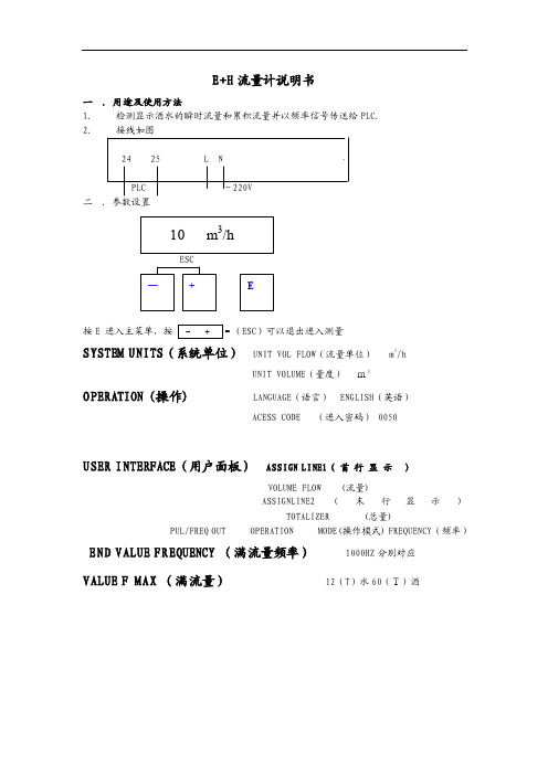
E+H 流量计说明书一 .用途及使用方法 1. 检测显示酒水的瞬时流量和累积流量并以频率信号传送给PLC. 2. 接线如图24 25 L NPLC ~220V 二 .参数设臵按E 进入主菜单,按ESC )可以退出进入测量SYSTEM UNITS (系统单位) UNIT VOL FLOW (流量单位) m 3/hUNIT VOLUME (量度) m3OPERATION (操作) LANGUAGE (语言) ENGLISH (英语)ACESS CODE (进入密码) 0050USER INTERFACE (用户面板) ASSIGN LINE1( 首 行 显 示 )VOLUME FLOW (流量)ASSIGNLINE2(末行显示)TOTALIZER (总量)PUL/FREQ OUT OPERATION MODE(操作模式) FREQUENCY (频率)END VALUE FREQUENCY (满流量频率) 1000HZ 分别对应 VALUE F MAX (满流量) 12(T )水60(T)酒二、安装1.安装位臵只有当满管时才能获得准确的测量,要避免以下安装位臵:(1)管道最高点(易聚积气泡);(2)直接向下的管线的敞开出口前;(3)泵的入口侧(防止抽压而造成的对流量管衬里的破坏);(4)有残渣聚积的场合和排水管的最低点(最好安装一个清洁阀)。
2.安装方位最适宜的方位可帮助避免气体的累积和测量管内的残渣存积。
垂直安装、流体自下而上的安装位臵为最佳方位。
若为水平安装,测量电极平面必须水平,这样可以防止由于夹带的气泡而产生的电极短时间绝缘。
空管检测功能仅当测量装臵为水平安装及变送器外壳向上时能正确工作。
3.振动如果振动剧烈,注意支撑管道和传感器;若振动非常剧烈应将传感器和变送器分开安装。
不允许利用外框承住传感器的重量,这会使外框变形并破坏内部励磁线圈。
4.出入口直管段安装传感器时要尽量避免阀门、三通、弯头等组件,与他们之间的距离应能保证所需的进口和出口直管段以确保测量精度:入口长度≥5DN,出口长度≥2DN。
- 1、下载文档前请自行甄别文档内容的完整性,平台不提供额外的编辑、内容补充、找答案等附加服务。
- 2、"仅部分预览"的文档,不可在线预览部分如存在完整性等问题,可反馈申请退款(可完整预览的文档不适用该条件!)。
- 3、如文档侵犯您的权益,请联系客服反馈,我们会尽快为您处理(人工客服工作时间:9:00-18:30)。
《传感器技术及应用》课程设计说明书课设题目流量检测系统班级姓名学号指导教师时间摘要流量是三大工业过程控制量之一,流量计量直接关系到国家利益和国计民生。
电磁流量计因测量时不受被测介质的温度、粘度、密度等影响,应用领域非常广泛。
因此,设计一个流量检测系统。
设计的流量检测系统以AT89C51单片机为核心,管道流量的检查采用电磁流量计,电磁流量计输入4~20mA的电流信号,通过I/A转为0~5V的电压信号,经AD转换送与单片机转换为流量数据,在液晶屏幕LCD1602中显示。
该流量检测系统可检测小口径管道流量,因不受流体材料的限制,常应用于食品工业。
关键词:电磁流量计,AT89C51单片机目录一、绪论1.1课题开发的背景和现状1.2课题开发的目的和意义1.3课题技术性能指标二、流量计种类选择方案三、系统总体方案设计四、主要器件的方案选择4.1、HR-LDG系列电磁流量传感器4.2、单片机的方案选择五、模块电路的设计5.1、MCU主控电路5.2、LCD1602液晶显示电路5.3、电流/电压转换电路5.4、A/D转换电路5.5、电源模块六、电磁流量计安装时注意事项七、系统软件开发流程及代码分析八、设计总结九、参考文献附录1、总电路图2、元器件清单一、绪论1.1课题开发的背景和现状工业生产中过程控制是流量测量和仪表应用的一大领域,流量与温度、压力和物位一起称为过程控制中的四大参数,人们通过这些参数对生产过程进行监视与控制。
对流体流量进行正确测量和调节是保证生产过程安全经济运行、提高产品质量、降低物质消耗、提高经济效益、实现科学管理的基础。
流量的检测与控制在化工、能源电力、冶金、石油等领域应用广泛。
例如:在天然气工业蓬勃发展的现在,天然气的计量收起了人们的特别关注,因为在天然气的采集、处理储存、运输和分配过程中,需要数以百万计的流量计,其中流量蠩涉及到的结算金额数字巨大,对测量和控制准确度和可靠性要求特别训。
此外,在环境保护领域,流量测量仪表也分演着重要角色。
人们为了控制大气的污染,必须对污染大气的烟气以及其分温室气体排放进行监测;废液和污水的排放,使地表水源和地下水源受到污染,人们必须对废液和污水进行处理,对排放量进行控制。
于是数以百万计的烟气排放点和污水排放口都成了流量测理对象。
同时在科学试验领域,需要大量的流量控制系统进行仿真与试验,流量计在现代家业、水利建设、生物工程、管道输送、航天航空、军事领域等也有广泛的应用。
1.2课题开发的目的和意义在现代工业生产过程自动化中,流量是重要的过程参数之一。
流量是衡量设备的效率和经济性的重要指标;流量是生产操作和控制的依据,因为在大多数工业生产中,常用测量和控制流量来确定物料的配比与耗量,实现生产过程自动化和最优控制。
同时为了进行经济核算,也必须知道如一个班组流过的介质总量。
所以,流量的测量与控制是实现工业生产过程自动化的一项重要任务。
例如:由于石油是重要的能源,无论上从节约能源的角度,还是从经济性角度来看,对于流量的精确控制都是十分必要的,所产生的经济效益也是十分明显的。
在自来水的监测与流量控制中,应用高精度的流量计量与控制仪表也是必须的,所带来的经济效益是十分巨大且显而易见的。
开展石油化工过程流程模拟、先进控制与过程优化技术的研究与应用具有十分重要的现实意义,是当前国内外石油化工界广泛关注的一个话题。
自动化技术可以提高计量准确度、数据可靠性和及时性,为优化生产运行、核算经济效益、强化生产调度和有效监控生产过程,进一步降低泵站工业噪声污染,改善职工工作条件,减轻劳动强度,避免职业伤害,延长设备使用寿命以及企业节能降耗工作起到积极作用。
1.3课题技术性能指标(1)小口径的电磁流量计,应用于食品工业;(2)检测管道的流量;(3)所测流量送液晶显示。
二、流量计种类选择方案目前,常用的流量计有:涡轮流量计、电磁流量计和明渠流量计3种。
因此,初步有三种方案设计可选用。
1、方案一采用明渠流量计进行流量的检测。
HOH-L-01多普勒明渠流量计测量系统的组成方法一般由一台流量显示仪、一台流速计、一台液位计组成;也可由一台流量显示仪、多台流速计、一台液位计组成的多点流速测量的明渠流量系统。
HOH-L-01多普勒明渠流量计系统,适用于水库、河流、水利工程、城市供水、污水处理、农田灌溉、水政水资源等矩形、梯形明渠及涵洞的流量测量,此次设计中应用于食品工业,故不适合使用明渠流量计。
2、方案二采用涡轮流量计进行流量检测。
涡轮流量计由涡轮、轴承、前置放大器、显示仪表组成。
被测流体冲击涡轮叶片,使涡轮旋转,涡轮的转速随流量的变化而变化,即流量大,涡轮的转速也大,再经磁电转换装置把涡轮的转速转换为相应频率的电脉冲,经前置放大器放大后,送入显示仪表进行计数和显示,根据单位时间内的脉冲数和累计脉冲数即可求出瞬时流量和累积流量。
涡轮流量计在一些对于准确度要求不高的场合得到了广泛的应用,但其不能长期保持校准特性,流体对流量特性有较大影响,对于食品安全流量检测,不适合于用此涡轮流量计。
3、方案三采用电磁流量计进行流量检测。
电磁流量计的测量管是一个内衬绝綠材料非导磁合金短管。
两只电极沿径方向透壁固定在测量管上,其电极头与衬头内表面基本齐平。
励磁线圈由双向方波脉冲劢磁时,将在与测量管轴线垂直的方向上产生一磁通量密度为B的工作磁场,此时,如果具有一定电导率的液体流经测量管,将切割磁力线感应出电动势E。
电动势E正比于磁通量密度B、测量管内径d与平均流速V的乘积。
电动势E(流量信号)由电极检出并通过电缆送至转换器。
转换器将流量信号放大处理后,可显示流体流量,并能输出脉冲,模拟电流等信号,用于流量的控制与调节。
电流量计有如下特点:(1)属于非接触性仪表,测量管段是光滑直管,管内没有任何阻碍流体流动的节流元件,不会引起额外的压力损失,节能效果好,可用于测量各种粘度的液体,特别适于测量含固体颗粒的液固混合流。
此外除电极外没有其他组件与液体直接接触,因此它还适于测量腐蚀性大的液体,由此形成了独特的应用领域。
(2)流量计测量过程不受被测介质的温度、粘度、密度等因素的影响,因此只需一次经水标定后就可用于测量其他导电液体的流量。
(3)电磁场的产生是极快的过程,因此电磁流量计反应速度快,无机械惯性,可以测量瞬时流量,还可测水平或垂直管道中两个轴向的流量。
(4)流量计输出只与被测介质的流速有关,量程范围宽。
(5)应用口径范围大,小口径、微小口径常用于医药卫生等有卫生要求的场所,中小口径常用于高要求或难测场合,如造纸工业测量纸浆液,大口径多用于给排水工程。
对比以上三种方案,方案一中适合应用于水库、河流、水利工程、城市供水、污水处理、农田灌溉、水政水资源等矩形、梯形明渠及涵洞的流量测量,此次设计中应用于食品工业,管道内流量的流速测量,故不适合使用明渠流量计。
方案二中涡轮流量计主要应用于石油、有机液体、无机液,液化气,天然气和低温流体,不适合选用涡轮流量计。
方案三中流量计测量过程不受被测介质的温度、粘度、密度等因素的影响,因此只需一次经水标定后就可用于测量其他导电液体的流量,可用于食品工业流速的检测,因此对比前两种方案可得此次设计中采用电磁流量计进行流速的检测。
三、系统总体方案设计工作原理:基于电磁流量计的管道流量检测系统实现的功能为检测管道的流量,送液晶显示。
管道流量的检查采用电磁流量计,电磁流量计输入4~20mA 的电流信号,通过I/A转为0~5V的电压信号,经AD转换送与单片机转换为流量数据,在液晶屏幕LCD1602中显示。
系统框图见图:系统框图四、主要器件的方案选择4.1、HR-LDG系列电磁流量传感器一般工业用电磁流量计被测介质流速为2~4m/s为宜,在特殊情况下,最低流速应不小于0.1m/s,最高不大于8m/s。
若介质中含有固体颗粒,常用流速应小于3m/s,以防止衬里和电极的过分摩擦:对于粘滞流体,流速可选择大于2m/s,较大的流速有助于自动消除电极上附着的粘滞物的作用,有利于提高测量精度。
在流量Q已确定的条件下,即可根据上述流速V的范围决定流量计口径D的大小,其值计算公式为:Q=πD2V/4式中,Q:流量(m3/h);D:管道内径(m);V:流速(m/h)。
(1)电磁流量计的工作原理与组成电磁流量计的测量管是一个内衬绝綠材料非导磁合金短管。
两只电极沿径方向透壁固定在测量管上,其电极头与衬头内表面基本齐平。
励磁线圈由双向方波脉冲劢磁时,将在与测量管轴线垂直的方向上产生一磁通量密度为B的工作磁场,此时,如果具有一定电导率的液体流经测量管,将切割磁力线感应出电动势E。
电动势E正比于磁通量密度B、测量管内径d与平均流速V的乘积。
电动势E(流量信号)由电极检出并通过电缆送至转换器。
转换器将流量信号放大处理后,可显示流体流量,并能输出脉冲,模拟电流等信号,用于流量的控制与调节。
导电性液体在垂直磁场的非磁性测量管内流动,与流动方向垂直的方向上产生与流量成比例的感应电势,电动势的方向按“弗来明右手规则”,其计算公式为E=kBD V(式1)式中,E:感应电动势,即流量信号,V;K:系数;B磁感应强度,T;D:测量管内径,m;V:平均流速,m/s.设液体的体积流量为qv (m3/s), qv=πD2V/4 (式2)则E=(4kB/πD)qv =kqv(式3)式中K为仪表常数,K=4kB/πD。
式1中K、d为常数,由于励磁电流是恒流的,因此B也是常数。
由E=kBD V可知,体积流量Q与信号电压E成正比,即流速感应的信号灯电压E与体积流量Q成线性关系。
因此,只要测量出E就可以确定流量Q,这就是电磁流量计的基本工作原理。
由E=kBD V可知,被测流体介质的温度、密度、压力、电导率、液固两相流体介质的液固成公比等参数不会影响测量结果。
至于流动状态,只要符合轴对称流动就不会影响测量结果。
因此,电磁流量计是一种真正的流量计。
对于制造厂和用用户来说,只要用普通的的水实际标定后就可测量其他任何导电流体的体积,而不需要任何修正,这是电磁流量计的一突出特点,也是其他任何流量计所没有的。
测量管内无活动及阻流部件,因此几乎没有压力损失,并具有很高的可靠性。
EMF由流量传感器和转换器两大部分组成。
传感器的测量管上下装有激磁线圈,能激磁电流后产生磁场穿过测量管,一对电极装在测量管内壁与液体相接触,引出感应电势,送到转换器。
激磁电流则由转换器提供。
(2)电磁流量传感器的选择电磁流量计的量程Q应大于预计的最大流量值,而正常的流量值以稍大于流量计满量程高刻度的50%为宜。
口径大小与流量范围对应如下表所示。
表2 口径大小与流量范围对应参考表在本系统中选用HR-LDG-D25-T0-F1-C0-E1-H0-G1-D型电磁流量计,流量范围为0.4~14 m3/h,介质温度为0℃-80℃,衬里材料为耐磨橡胶,电极材料为216L,工作压力为2.5Mpa,全系列口径,连接方式为法兰式,转换器结构为一体式智能表头,220VAC供电电压,输出为4-20mA,防爆类型为隔爆型。