虚拟示波器的研究和开发中英文对照
数字示波器外文翻译文献
数字示波器外文翻译文献(文档含中英文对照即英文原文和中文翻译)原文:Design and FPGA implementation of a wireless hyperchaotic communication system for secure real-time image transmission AbstractIn this paper, we propose and demonstrate experimentally a new wireless digital encryption hyperchaotic communication system based on radio frequency (RF) communication protocols for secure real-time data or image transmission. A reconfigurable hardware architecture is developed to ensure the interconnection between two field programmable gate array developmentplatforms through XBee RF modules. To ensure the synchronization and encryption of data between the transmitter and the receiver, a feedback masking hyperchaotic synchronization technique based on a dynamic feedback modulation has been implemented to digitally synchronize the encrypter hyperchaotic systems. The obtained experimental results show the relevance of the idea of combining XBee (Zigbee or Wireless Fidelity) protocol, known for its high noise immunity, to secure hyperchaotic communications. In fact, we have recovered the information data or image correctly after real-time encrypted data or image transmission tests at a maximum distance (indoor range) of more than 30 m and with maximum digital modulation rate of 625,000 baud allowing a wireless encrypted video transmission rate of 25 images per second with a spatial resolution of 128 ×128 pixels. The obtained performance of the communication system is suitable for secure data or image transmissions in wireless sensor networks.IntroductionOver the past decades, the confidentiality of multimedia communications such as audio, images, and video has become increasingly important since communications of digital products over the network (wired/wireless) occur more frequently. Therefore, the need for secure data and transmission is increasing dramatically and defined by the required levels of security depending on the purpose of communication. To meet these requirements, a wide variety of cryptographic algorithms have been proposed. In this context, the main challenge of stream cipher cryptography relates to the generation of long unpredictable key sequences. More precisely, the sequence has to be random, its period must be large, and the various patterns of a given length must be uniformly distributed over the sequence. Traditional ciphers like DES, 3DES, IDEA, RSA, or AES are less efficient for real-time secure multimedia data encryption systems and exhibit some drawbacks and weakness in the high streamdata encryption. Indeed, the increase and availability of a high-power computation machine allow a force brute attack against these ciphers. Moreover, for some applications which require a high-levelcomputation and where a large computational time and high computing power are needed (for example, encryption of large digital images), these cryptosystems suffer from low-level efficiency. Consequently, these encryption schemes are not suitable for many high-speed applications due to their slow speed in real-time processing and some other issues such as in the handling of various data formatting. Over the recent years, considerable researches have been taken to develop new chaotic or hyperchaotic systems and for their promising applications in real-time encryption and communication. In fact, it has been shown that chaotic systems are good candidates for designing cryptosystems with desired properties. The most prominent is sensitivity dependence on initial conditions and system parameters, and unpredictable trajectories.Furthermore, chaos-based and other dynamical systembased algorithms have many important properties such as the pseudorandom properties, ergodicity and nonperiodicity. These properties meet some requirements such as sensitivity to keys, diffusion, and mixing in the cryptographic context. Therefore, chaotic dynamics is expected to provide a fast and easy way for building superior performance cryptosystems, and the properties of chaotic maps such as sensitivity to initial conditions and random-like behavior have attracted the attention to develop data encryption algorithms suitable for secure multimedia communications. Until recently, chaotic communication has been a subject of major interest in the field of wireless communications. Many techniques based on chaos have been proposed such as additive chaos masking (ACM), where the analog message signal is added to the output of the chaos generator within the transmitter. In, chaos shift keying is used where the binary message signal selects the carrier signal from two or more different chaotic attractors. Authors use chaotic modulation where the message information modulates a parameter of the chaotic generator. Chaos control methods rely on the fact that small perturbations cause the symbolic dynamics of a chaotic system to track a prescribed symbol sequence. In, the receiver system is designed in an inverse manner to ensure the recovery of theencryption signal. An impulsive synchronization scheme is employed to synchronize chaotic transmitters and receivers. However, all of these techniques do not provide a real and practical solution to the challenging issue of chaotic communication which is based on extreme sensitivity of chaotic synchronization to both the additive channel noise and parameter mismatches. Precisely, since chaos is sensitive to small variations of its initial conditions and parameters, it is very difficult to synchronize two chaotic systems in a communication scheme. Some proposed synchronization techniques have improved the robustness to parameter mismatches as reported in, where impulsive chaotic synchronization and an open-loop-closed-loopbased coupling scheme are proposed, respectively. Other authors proposed to improve the robustness of chaotic synchronization to channel noise, where a coupled lattice instead of coupled single maps is used to decrease the master-slave synchronization error. In, symbolic dynamics-based noise reduction and coding are proposed. Some research into equalization algorithms for chaotic communication systems are also proposed. For other related results in the literature, see. However, none of them were tested through a real channel under real transmission conditions. Digital synchronization can overcome the failed attempts to realize experimentally a performed chaotic communication system. In particular, when techniques exhibit any difference between the master/transmitter and slave/receiver systems, it is due to additive information or noise channel (disturbed chaotic dynamics) which breaks the symmetry between the two systems, leading to an accurate non-recovery of the transmitted information signal at the receiver. In, an original solution to the hard problem of chaotic synchronization high sensibility to channel noise has been proposed. This solution, based on a controlled digital regenerated chaotic signal at the receiver, has been tested and validated experimentally in a real channel noise environment through a realized wireless digital chaotic communication system based on zonal intercommunication global-standard, where battery life was long, which was economical to deploy and which exhibited efficient use of resources, knownas the ZigBee protocol. However, this synchronization technique becomes sensible to high channel noise from a higher transmission rate of 115 kbps, limiting the use of the ZigBee and Wireless Fidelity (Wi-Fi) protocols which permit wireless transmissions up to 250 kbps and 65 Mbps, respectively.Consequently, no reliable commercial chaos-based communication system is used to date to the best of our knowledge. Therefore, there are still plentiful issues to be resolved before chaos-based systems can be put into practical use. To overcome these drawbacks, we propose in this paper a digital feedback hyperchaotic synchronization and suggest the use of advanced wireless communication technologies, characterized by high noise immunity, to exploit digital hyperchaotic modulation advantages for robust secure data transmissions. In this context, as results of the rapid growth of communication technologies, in terms of reliability and resistance to channel noise, an interesting communication protocol for wireless personal area networks (WPANs, i.e., ZigBee or ZigBee Pro Low-Rate-WPAN protocols) and wireless local area network (WLAN, i.e., Wi-Fi protocol WLAN) is developed. These protocols are identified by the IEEE 802.15.4 and IEEE 802.11 standards and known under the name ZigBee and Wi-Fi communication protocols, respectively. These protocols are designed to communicate data through hostile Radio Frequency (RF) environments and to provide an easy-to-use wireless data solution characterized by secure, low-power, and reliable wireless network architectures. These properties are very attractive for resolving the problems of chaotic communications especially the high noise immunity property. Hence, our idea is to associate chaotic communication with theWLAN or WPAN communication protocols. However, this association needs a numerical generation of the chaotic behavior since the XBee protocol is based on digital communications.In the hardware area, advanced modern digital signal processing devices, such as field programmable gate array (FPGA), have been widely used to generate numerically the chaotic dynamics or the encryption keys. The advantage of these techniques is that the parameter mismatch problem does not existcontrary to the analog techniques. In addition, they offer a large possible integration of chaotic systems in the most recent digital communication technologies such as the ZigBee communication protocol. In this paper, a wireless hyperchaotic communication system based on dynamic feedback modulation and RF XBee protocols is investigated and realized experimentally. The transmitter and the receiver are implemented separately on two Xilinx Virtex-II Pro circuits and connected with the XBee RF module based on the Wi-Fi or ZigBee protocols. To ensure and maintain this connection, we have developed a VHSIC (very high speed integrated circuit) hardware description language (VHDL)-based hardware architecture to adapt the implemented hyperchaotic generators, at the transmitter and receiver, to the XBee communication protocol. Note that the XBee modules interface to a host device through a logic-level asynchronous serial port. Through its serial port, the module can communicate with any logic and voltage-compatible Universal Asynchronous Receiver/Transmitter (UART). The used hyperchaotic generator is the well-known and the most investigated hyperchaotic Lorenz system. This hyperchaotic key generator is implemented on FPGA technology using an extension of the technique developed in for three-dimensional (3D) chaotic systems. This technique is optimal since it uses directly VHDL description of a numerical resolution method of continuous chaotic system models. A number of transmission tests are carried out for different distances between the transmitter and receiver. The real-time results obtained validate the proposed hardware architecture. Furthermore, it demonstrates the efficiency of the proposed solution consisting on the association of wireless protocols to hyperchaotic modulation in order to build a reliable digital encrypted data or image hyperchaotic communication system.Hyperchaotic synchronization and encryption techniqueContrary to a trigger-based slave/receiver chaotic synchronization by the transmitted chaotic masking signal, which limits the performance of the rate synchronization transmission, we propose a digital feedback hyperchaoticsynchronization (FHS). More precisely, we investigate a new scheme for the secured transmission of information based on master-slave synchronization of hyperchaotic systems, using unknown input observers. The proposed digital communication system is based on the FHS through a dynamic feedback modulation (DFM) technique between two Lorenz hyperchaotic generators. This technique is an extension and improvement of the one developed in for synchronizing two 3D continuous chaotic systems in the case of a wired connection.The proposed digital feedback communication scheme synchronizes the master/transmitter and the slave/receiver by the injection of the transmitted masking signal in the hyperchaotic dynamics of the slave/receiver. The basic idea of the FHS is to transmit a hyperchaotic drive signal S(t) after additive masking with a hyperchaotic signal x(t) of the master (transmitter) system (x , y , z ,w ). Hyperchaotic drive signal is then injected both in the three subsystems (y , z ,w ) and (r r r w z y ,,). The subscript r represents the slave or receiver system (r r r r w z y x ,,,). At the receiver, the slave system regenerates the chaotic signal )(t x r and a synchronization is obtained between two trajectories x(t) and )(t x r if()()0||lim =-∞→t X t X r t (1) This technique can be applied to chaotic modulation. In our case, it is used for generating hyperchaotic keys for stream cipher communications, where the synchronization between the encrypter and the decrypter is very important. Therefore, at the transmitter, the transmitted signal after the additive hyperchaos masking (digital modulation) isS(t) = x(t) + d(t). (2)where d(t) is the information signal and x(t) is the hyperchaotic carrier. At the receiver, after synchronization of the regenerated hyperchaotic signal )(t x rwith the received signal )(t S r and the demodulation operation, we can recover the information signal d(t) correctly as follows:)()()(t x t S t d r r -=. (3)Therefore, the slave/receiver will generate a hyperchaotic behavior identical to that of the master/transmitter allowing to recover correctly the information signal after the demodulation operation. The advantageof this technique is that the information signal d(t) doesnot perturb the hyperchaotic generator dynamics, contraryto the ACM-based techniques of and, because d(t) is injected at both the master/transmitter and slave/receiver after the additive hyperchaotic masking. Thus, for small values of information magnitude, the information will be recovered correctly. It should be noted that we have already confirmed this advantage by testing experimentally the HS-DFM technique performances for synchronizing hyperchaotic systems (four-dimensional (4D) continuous chaotic systems) in the case of wired connection between two Virtex-II Pro development platforms. After many experimental tests and from the obtained real-time results, we concluded that the HS-DFM is very suitable for wired digital chaotic communication systems. However, in the present work, one of the objectives is to test and study the performances of the HS-DFM technique in the presence of channel noise through real-time wireless communication tests. To performthe proposed approach, a digital implementation of the master and slave hyperchaotic systems is required. Therefore, we investigate the hardware implementation of the proposed FHS-DFM technique between two Lorenz hyperchaotic generators using FPGA. To achieve this objective, we propose the following details of the proposed architecture.译文:无线超混沌通信系统安全的实时图像传输的设计和FPGA实现摘要在本文中,我们提出并论证了一种基于无线电频率通信协议对数据或图像安全实时传输的新的无线数字超混沌加密通信系统。
虚拟函数波形发生器中英文对照外文翻译文献
中英文资料外文翻译(文档含英文原文和中文翻译)The Design of Virtual Function waveform GeneratorAbstract—In this paper, a Virtual Function Signal Generator is designed Based on Labview. How to design the generator is introduced in detail. The Virtual Function Signal Generator can generate basic wave such as Sine wave, formula wave, white noise etc. The generator has functions like wave showing and date saving in addition.Keywords- Virtual Instrument; Labview;Function Signal GeneratorI. INTRODUCTIONThe function signal generator is applied in great many of fields. Virtual Instrument is a new type of instrument which has especial functions that old one do not have. One VI includes PC, hardware which is particularly designed and special software. Being a graphical programming language Labview is used for date gathering, instrument controlling and date analyzing. How to design virtual function signal generator by Labview is explained in detail in the following paper.II. TOTAL DESIGNAccording to the principle of function signal generator,four parts were designed to compose virtual function signal generator. These four parts are property setting, signal generating, wave showing and date saving.A. Panel of GeneratorIn this system the panel are divided to property setting panel(fig.1) and total structure panel(fig.2) . Main options in the first one are frequency, amplitude, duty cycle and samples etc. about signal. These properties can be set in this panel. Total structure panel just includes four parts that were presented above and some additional parts.Figure 1.Property Set Panel Figure2.Total Structure PanelB. Function about InstrumentsThe Virtual Function Signal Generator can generate basic waves such as Sine wave , special waves like formula wave and some kinds of noise. Signal’s frequency can be regulated delicately or roughly. Property can be reset quickly and be used as subprogram sometimes. Moreover has the generator functions like wave showing and date saving etc.III. SOFTWARE ABOUT VIRTUAL FUNCTION SIGNALGENERATORThe Virtual Function Signal Generator was designed base on Labview 7.0. There are three modules which compose this system: module of property setting, wave generating, wave showing and saving.A. Module of Property SettingFrequency setting and property resetting are two important parts of this module. How to change frequency value multiply is explained in fig.3. Node Selectting isapplied repeatedly and skillfully so that data can be input in manychannels. Then select data by switchbutton. So frequency controlling canbe designed as real instrument. Howto reset property quickly is explainedin fig.4.Figure4. Property ResetFigure3. Frequency ControlB. Module of Wave GeneratingThis module is the core of the Virtual Function Signal Generator. Structure CASE is used in this work. By special node many types of waves can be generated. For example, how to generate sine wave is explained in fig.5. The other ones can be generated in similar way.Figure5.Graphical Progranm About Sine Wave GenerateC. Module of Wave Showing and SavingIn fact this module is a composite one which include many functions as operating, applying, debugging, showing etc. Because of lots of acts would be operated though this interface, this interface must be not only practical but also nice. Fig.6 just explained how to solve these problems.Figure6.Graphical Program About TotalIV. CONCLUSIONBeing graphical language, Labview is very strong and easy tool to make system of measure and test. Virtual Function Signal Generator based on Labview has advantages such as having friendly interface, operating easily etc. It can generate many types of function signals which have big range of value of frequency and its output datas can be saved. So it can be applied widely.虚拟函数波形发生器的设计摘要在本次设计中,虚函数信号发生器是基于相位差来设计的。
示波器实验报告英文

示波器实验报告英文Experiment Report on Oscilloscope1. IntroductionThe oscilloscope is a widely used test instrument in electronics and electrical engineering. It allows for the visualization and analysis of electrical signals in the time domain. This experiment aims to familiarize students with the operation and usage of an oscilloscope.2. Experimental SetupThe experimental setup consists of an oscilloscope, a function generator, and various electrical components such as resistors, capacitors, and inductors. The function generator generates electrical waveforms of different frequencies and amplitudes, which are connected to the input of the oscilloscope. The oscilloscope displays the waveform on its screen and provides various controls for adjusting the display parameters.3. Experimental Procedure- Connect the function generator output to the input of the oscilloscope using a coaxial cable.- Turn on the oscilloscope and adjust the vertical and horizontal controls to obtain a clear waveform display.- Adjust the time base control to change the time scale of the waveform. - Measure the amplitude and frequency of the waveform using the appropriate controls on the oscilloscope.- Connect different electrical components (resistors, capacitors, and inductors) in series or parallel with the function generator output and observe the effects on the waveform display.- Record the observed changes in waveform amplitude, frequency, and shape due to the introduced components.4. Results and Analysis- The oscilloscope accurately displays the waveform generated by the function generator.- The measured amplitude and frequency of the waveform match the values set on the function generator.- The introduction of electrical components such as resistors, capacitors, and inductors affects the waveform amplitude, frequency, and shape.- The amplitude of the waveform decreases with the introduction of a resistor, indicating a voltage drop across the resistor.- The introduction of a capacitor or inductor changes the waveform shape, depending on the frequency of the waveform and the reactance of the component.5. ConclusionThis experiment provided an introduction to the oscilloscope and its operation. It demonstrated the accurate display of electrical waveforms and the effects of different electrical components on the waveform shape. The oscilloscope is an essential tool for engineers and technicians in analyzing and troubleshooting electrical circuits. Familiarity with its usage is crucial for any electronics or electrical engineering student.。
LabView虚拟示波器的实验报告
LabView虚拟示波器实验报告虚拟仪器课程设计题目: 双通道示波器学生姓名:学号:专业:班级:指导教师:双通道虚拟示波器 1.设计题目: 双通道虚拟示波器2设计目的:了解、熟悉并掌握DAQ功能和使用以及虚拟仪器的相关知识,完成双通道虚拟示波器要求功能(幅值、频率、周期、占空比,均方根)的设计 3.设计要求:(1)将信号发生器发出的波形由虚拟示波器进行采集显示相关测量数据。
(2)能够完成波形的采集显示,具有双通道特性。
(3)可以选择不同的显示通道4.设计原理:采用NI DAQ PCI-6221板卡外接信号作为信号源,当程序运行起来后选择不同的显示通道。
首先,使用一个While循环形成一个死循环使程序一直运行下去,然后通过一个条件选择结构判断程序是否运行,同时可以在此设置程序的启停,条件结构里面通过不同的条件选择不同的输出波形通道,再由数据采集系统采集实时信息送至波形显示控件及数据统计分析进行动态显示。
在前面板上同时显示频率、幅值、周期、占空比、均方值等数值信息5(设计步骤:(1)启动LabVIEW2013,进入程序运行界面,新建一个VI程序。
打开程序框图窗口,在程序面板编写双路示波器发生器的程序。
在框图中的面板上单击鼠标右键弹出功能选板,在编程结构中选中While循环和条件循环,拖动鼠标至一定的大小完成循环。
首先设计整体的while循环,然后设置双路示波器要测量的参数,包括采样频率、幅值、周期,占空比等,再配置可调大小的旋钮。
(2)while循环结构和条件选择框图如下图:2(3)模拟通道采样方式及其他参数设置模块程序框图如图:(4)DAQmx 模拟量采集系统各模块的选择从“程序框图”面板中点击鼠标右键,然后按照“测量I/O”——“DAQ”——“DAQ mx”的顺序在列表中找到“DAQmx Create Virtual Channel”,拖到面板中如图示:设定最大最小值及其通道值按上述方法在“DAQ mx”并列位置找到“采样时钟”模块,如图示:3开辟缓存区大小设置采样时钟为Sample Clock采样方式为Continuous Samples “DAQ mx”下找到“DAQ读取”模块,设置如下图同样在“DAQmx”中找到“stop”如下图然后找到“DAQmx清除任务”模块如下图4使用搜索功能,在对话框与用户选版中找到“简单错误输出处理” 模块如下图所示:(5)模拟通道采样方式及其他参数设置模块程序框图如图:(6)数据存储模块:在输出express VI中找到“写入测量”模块如图:(7)显示通道选择功能:5条件结构共分3层0、1、2及默认层分别代表1通道,2通道,双通道12、默认,各层如下:通道1程序框图如下图:通道2程序框图如下图:双通道12程序框图如下图:前面板图形如下:6(8)数据统计分析显示功能在信号处理VI/波形测量VI下找到“幅值和电平”模块并设置幅值和均方根显示模块并拖到面板如下图所示:前面板图形如下:同样方法在信号分析express VI 下找到“信号的时间与瞬态特性测量”模块并添加设置频率、周期、占空比显示控件如下图所示:前面板图形如下:7以上这些程序模块用于对采样波形信息进行分析、处理及实时的动态显示,显示到虚拟示波器上。
基于LabVIEW的虚拟数字存储示波器的研究
基于LabVIEW的虚拟数字存储示波器的研究摘要:示波器是在科学研究和工程设计中广泛应用的一种通用仪器。
基于虚拟仪器技术,开发了一种新型示波器—虚拟数字存储示波器。
通过采集卡完成数据采集任务,借助于LabVIEW软件实现数据分析和结果输出存储等功能,是对传统示波器的有效更新与变革。
关键词:示波器虚拟仪器数据采集LabVIEWVirtual Digital Storage Oscillograph Based on LabVIEWAbstract:Oscillograph is a kind of general instrument extensively used in science research and engineering design.A new type of virtual digit storage oscillograph is developed based on virtual instrument technology.By use of acquisitin card,digit acquisition task is finished.By use of LabVIEW software,the function of digit analysis and result output and memory is realized.This product is efficiently renovating and changing to traditional oscillograph field.Key Words:Oscillograph;Virtual instrument;Data acquisition;LabVIEW随着科学技术的飞速发展,测试领域需要不断更新检测设备,以满足工业生产及科研开发需求。
在我国,传统测试仪器自动化程度较低,其测量精度和可靠性均低于国外,而高档测试仪器基本上依靠国外进口,不但造价高,而且功能单一、适用范围窄。
西安工业大学物理实验室模拟电子示波器实验内容及步骤
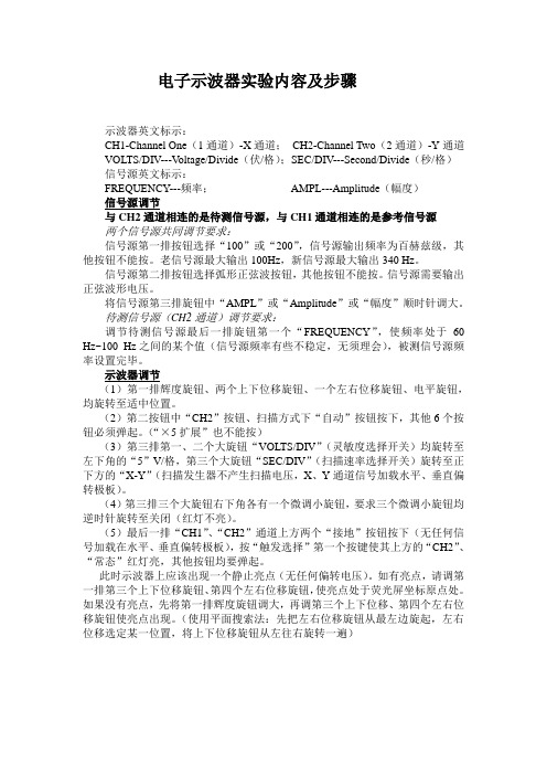
电子示波器实验内容及步骤示波器英文标示:CH1-Channel One(1通道)-X通道;CH2-Channel Two(2通道)-Y通道VOLTS/DIV---V oltage/Divide(伏/格);SEC/DIV---Second/Divide(秒/格)信号源英文标示:FREQUENCY---频率;AMPL---Amplitude(幅度)信号源调节与CH2通道相连的是待测信号源,与CH1通道相连的是参考信号源两个信号源共同调节要求:信号源第一排按钮选择“100”或“200”,信号源输出频率为百赫兹级,其他按钮不能按。
老信号源最大输出100Hz,新信号源最大输出340 Hz。
信号源第二排按钮选择弧形正弦波按钮,其他按钮不能按。
信号源需要输出正弦波形电压。
将信号源第三排旋钮中“AMPL”或“Amplitude”或“幅度”顺时针调大。
待测信号源(CH2通道)调节要求:调节待测信号源最后一排旋钮第一个“FREQUENCY”,使频率处于60 Hz~100 Hz之间的某个值(信号源频率有些不稳定,无须理会),被测信号源频率设置完毕。
示波器调节(1)第一排辉度旋钮、两个上下位移旋钮、一个左右位移旋钮、电平旋钮,均旋转至适中位置。
(2)第二按钮中“CH2”按钮、扫描方式下“自动”按钮按下,其他6个按钮必须弹起。
(“×5扩展”也不能按)(3)第三排第一、二个大旋钮“VOLTS/DIV”(灵敏度选择开关)均旋转至左下角的“5”V/格,第三个大旋钮“SEC/DIV”(扫描速率选择开关)旋转至正下方的“X-Y”(扫描发生器不产生扫描电压,X、Y通道信号加载水平、垂直偏转极板)。
(4)第三排三个大旋钮右下角各有一个微调小旋钮,要求三个微调小旋钮均逆时针旋转至关闭(红灯不亮)。
(5)最后一排“CH1”、“CH2”通道上方两个“接地”按钮按下(无任何信号加载在水平、垂直偏转极板),按“触发选择”第一个按键使其上方的“CH2”、“常态”红灯亮,其他按钮均要弹起。
示波器中的中英文 对照
示波器中英文对照翻译主菜单:File--------------文件Edit--------------编辑Settings---------设置View-------------查看Window---------窗口Automotive-----汽车一、File(文件)New---------------------新建Open--------------------打开Merge-------------------合并Save---------------------保持Save as------------------另存为Open next pgDn--------打开下一个文件Open previous pgUp---打开先前文件Print----------------------打印Save settings------------保存设置Setup---------------------设置Exit-----------------------退出✧Setup(设置)Converter----转换Language----语言Display------显示Clours-------色彩Display preference—显示参数Maximum displays per second---------------- 每秒钟最多显示屏幕数量Display notes in views-------------------------- 在屏幕中显示注解Display datestamp in views-------------------- 在屏幕中显示时间Display view bar at top ofwindow------------在窗口顶部显示设置工具栏Display sampling bar at bottom ofwindow---在窗口底部显示取样工具栏Colours(色彩)Color setting----颜色设置Background------背景颜色Grid---------------网格线颜色Text---------------文字颜色Ruler--------------标尺颜色Trance A----------综迹线A颜色Trance B----------综迹线B颜色二、E d i t(编辑)copy as Text-------------复制文字copy as Graph---------- 复制为图copy measurements---- 复制量度duplicate view---------- 复写查看三、settings(设置)timebase—时基channels—频道trigger—启动(触发)signal generator —信号发生器options—选项custom ranges —自定义范围notes—记录probes—探测器measurements —量度单位offset null—零偏移channels(频道)channels Aonly—仅显示A通道channels B only—仅显示B通道both channels, alternate —双通道交替显示both channels, chop—双通道单独显示voltage range—电压范围选择Yaxis—Y轴Coupling—耦合T rigger(启动或触发)Trigger enabled—触发选择Channel—触发通道Direction—方向Threshold—触发点Delay after—触发延迟时间选择Use equivalent time sampling —使用等时取样Auto trigger—自动触发Save on trigger—触发保存Stop after trigger—触发后停止Beep on trigger—触发时声音报警Options(选项)Scope options—示波器选项Display mode—显示类型:–Current(unfiltered)---即时数据显示(未滤波)–Current(F i l t e r e d)---即时数据显示(滤波)–Average—平均值–Min, Max & average—最小值,最大值,平均值Min, Max & current—最小值,最大值,即时值–—数值颜色–A n a l o gIntensity—模拟增强Saturation—饱和度Advanced—高级设置Display a grid—显示网格Display axis scaling—显示轴缩放比例Scope timebase is time per division —每单位网格时间四、v i e w(查看)new scope–新建范围new spectrum—new meter—新建仪表(万用表)new composite—新建合成run/stop all(s p a c e)--运行/停止(空格键)run/stop view --运行/停止查看freeze/thaw one—冻结/解除clear—清除close—关闭五、window(窗口)–并列cascade—重叠arrange icons—整理图标close all–关闭全部六、Help(帮助)Index—索引Contents—内容A b o u t—关于七、底部触发工具栏Go—继续Step停止Trigger—触发–None—不触发–A u t o—自动触发–Repeat-- 重复触发–Single—单次触发Rising—上升Falling。
Pico示波器中英文对照
示波器中英文对照翻译主菜单:File--------------文件Edit--------------编辑Settings---------设置View-------------查看Window---------窗口Automotive-----汽车一、File(文件)New---------------------新建Open--------------------打开Merge-------------------合并Save---------------------保持Save as------------------另存为Open next pgDn--------打开下一个文件Open previous pgUp---打开先前文件Print----------------------打印Save settings------------保存设置Setup---------------------设置Exit-----------------------退出Setup(设置)Converter----转换Language----语言Display------显示Clours-------色彩✧Display preference—显示参数Maximum displays per second----------------每秒钟最多显示屏幕数量Display notes in views--------------------------在屏幕中显示注解Display datestamp in views--------------------在屏幕中显示时间Display view bar at top of window------------在窗口顶部显示设置工具栏Display sampling bar at bottom of window---在窗口底部显示取样工具栏✧Colours(色彩)Color setting----颜色设置Background------背景颜色Grid---------------网格线颜色Text---------------文字颜色Ruler--------------标尺颜色Trance A----------综迹线A颜色Trance B----------综迹线B颜色二、Edit(编辑)copy as Text-------------复制文字copy as Graph----------复制为图copy measurements----复制量度duplicate view----------复写查看三、settings(设置)timebase —时基channels —频道trigger —启动(触发)signal generator—信号发生器options —选项custom ranges—自定义范围notes —记录probes—探测器measurements —量度单位offset null—零偏移✧channels(频道)channels A only—仅显示A通道channels B only—仅显示B通道both channels, alternate—双通道交替显示both channels, chop—双通道单独显示voltage range—电压范围选择Y axis—Y轴Coupling—耦合✧Trigger(启动或触发)Trigger enabled—触发选择Channel—触发通道Direction—方向Threshold—触发点Delay after—触发延迟时间选择Use equivalent time sampling—使用等时取样Auto trigger—自动触发Save on trigger—触发保存Stop after trigger—触发后停止Beep on trigger—触发时声音报警✧Options(选项)Scope options—示波器选项Display mode—显示类型:–Current(unfiltered)---即时数据显示(未滤波)–Current(Filtered)---即时数据显示(滤波)–Average—平均值–Min, Max & average—最小值,最大值,平均值–Min, Max & current—最小值,最大值,即时值–Digital color—数值颜色–Analog Intensity—模拟增强Saturation—饱和度Advanced—高级设置Display a grid—显示网格Display axis scaling—显示轴缩放比例Scope timebase is time per division—每单位网格时间四、view(查看)new scope –新建范围new spectrum—新建波谱new meter—新建仪表(万用表)new composite—新建合成run/stop all(space)--运行/停止(空格键)run/stop view --运行/停止查看freeze/thaw one—冻结/解除clear—清除close—关闭五、window(窗口)tile –并列cascade—重叠arrange icons—整理图标close all –关闭全部六、Help(帮助)Index—索引Contents—内容About—关于七、底部触发工具栏Go—继续Step—停止Trigger—触发–None—不触发–Auto—自动触发–Repeat--重复触发–Single—单次触发Rising—上升Falling—下降。
lab view的虚拟示波器设计与研究
21年第3 期 01 2
科技 圈向导
◇ 科技论坛◇
lb i aபைடு நூலகம் e v w的虚拟示波器设计与研究
吕 庆 ( 中国 兵器 北 方 雷 达 电 子 科技 集 团 陕 西
【 摘
西安
7 0O ) 1 1 0
要】 虚拟仪器的崛起是测试仪 器技术的一次革命 性的飞跃, 器领域的一个新的里程碑。虚拟仪器的核心思想是利用计算机的 强 是仪
器 的输 出信号和数据采集模块可 以接受的信号 联系起 来 . 传感 器输 从 出的信号必须经过调理才能够连人数据采集板 . 信号调理包 括放 大和 衰减 、 隔离 、 滤波 、 传感器激励 、 线性化处理。
f1 3数据采集硬件 数据采集硬件 与众多 因素有关 . 要根据具体情况进行分 析 . 下面 是通用 的特征: ①采样频率 31bve 虚 拟 示 波 器 的设 计 . i a w 采样频率高 . 就能在一定 时间内获得更多的原始信息 为了再现 3 i . l v w虚拟示波器的特点 1a e b 原始信号 , 必须有足够 高的采样频率 。 显然 , 如果信号 变化 比采样板的 l e a v w软件是 N 公司提供 的一种 图形方式编程软件 为是一 bi I 作 数字化要快 , 或采样太慢 , 就会产生波形失真。为了避免这一现象 . 要 种程序开发软件 , 其使用 了 G图形化) ( 的数据流编程模式, 别于基 于文 做到采样频率至少是输人最高频率 的两倍 本语言的线性结构 ⑦采样方法 l i a v w软件含 有丰 富的函数库 . 数据采样库 、 b e 如 数字信 号处理 要从多个通道得到数据 , 常使用多路开关把每个信号端连接到 通 和数值分 析库 、 数据表达库 、 数据存储库等 。另外 . 它还具备常规程序 A C 。采样方法主要 由连续扫描方法和间隔扫描方法两 的开发调试 功能 , 以方便地设置断点、 可 单步跟踪 . 直观地对程序进行 MD转化器( D ) 种 主要视采样点之间对时间的要求而定 动态调试并实时记 录
基于LabVIEW 的虚拟示波器开发及应用
基于LabVIEW的虚拟示波器开发及应用Development and Application of Virtual OscilloscopeBased on LabVIEW班级:0704114姓名:周超学号:07摘要:在LabVIEW 环境下通过调用动态链接库(DLL)函数的方法对DSO2902示波器进行了二次开发。
所开发的虚拟示波器具有2路模拟量采集通道,能够实现通道选择、数据采集、数据保存与回放、频谱分析、李沙育图形及波形参数测量功能。
仪器前面板界面友好,操作方便。
同时,本系统采用软冗余技术,提高了自动控制系统的可靠性, 避免了因PLC停机而引起控制系统出现故障。
关键词:虚拟示波器数据采集动态链接库绪论虚拟仪器是随着计算机技术、电子测量技术和通信技术而发展起来的一种新型仪器, 它是在以通用计算机为核心的硬件平台上, 由用户设计定义, 具有虚拟面板, 测试功能由测试软件实现的一种计算机仪器系统, 能够充分利用计算机系统强大的数据处理能力。
在自动测试与控制系统的集成中, 为了加快系统构建的速度,通常选取功能强大,价格合理的现成仪器硬件模块,结合自身开发的软件实现系统集成。
为了采集水射流等离子弧放电波形并将测量系统与控制系统集成, 本文对Link Instruments 公司的DSO2902 示波器硬件进行了二次开发。
该硬件模块具有2 路模拟量采集通道,采样频率可达250MHz,同时该公司还提供了实现模块硬件控制的动态链接库(DLL)。
在上述软硬件基础上,以LabVIEWE 为平台设计了满足自动测试系统要求的双通道虚拟数字存储示波器, 能够实现数据采集、数据保存与回放、频谱分析、李沙育图形及波形参数测量等功能。
1 硬件DLL函数及其调用方法1.1 DLL 函数说明在LabVIEW 中通过CLF (Call Library Function) 节点调用DLL 函数可以充分利用已有的硬件, 使得LabVIEW 的应用更加灵活和广泛。
- 1、下载文档前请自行甄别文档内容的完整性,平台不提供额外的编辑、内容补充、找答案等附加服务。
- 2、"仅部分预览"的文档,不可在线预览部分如存在完整性等问题,可反馈申请退款(可完整预览的文档不适用该条件!)。
- 3、如文档侵犯您的权益,请联系客服反馈,我们会尽快为您处理(人工客服工作时间:9:00-18:30)。
虚拟示波器的研究和开发摘要—本文介绍了一个基于LABVIEW设计虚拟仪器的过程。
该示波器主要分析用价值和时基法实现时间在振幅调整过程中的实时显示。
同时,它简单介绍了用栅压法测量时间和频率的波形的简单思路以及应用。
在结束时,本文将虚拟示波器中参数的测量与波形的显示和现代发动机闭环锁的定期速度控制联合起来,一起分析了在PID控制时参数测量的影响。
关键词-虚拟示波器,时基,运动控制1.引文在高速发展的工业控制领域,测量技术和仪器变得越来越重要。
但由于弊端的传统手段,如价格昂贵、功能单一、可扩展性不好等,很难满足业界的要求。
随着计算机技术和虚拟仪器的发展,用户的设计范围变得比较广泛。
用先进的总线技术,同样的硬件可以使两个或者两个以上的机器同步工作,实现很多不同的功能,如PXI总线技术。
这些突出的特点,例如成本低、多功能等使得虚拟仪器的使用越来越广泛。
所有的测量仪器都包括三个部分:数据采集部分,数据分析部分和结果输出部分。
在这三个部分中,数据采集部分可以由硬件系统的A/D模块或数字模块等10个模块来完成。
而数据分析和结果输出部分可由计算机基础上的软件系统来完成。
因此,如果给予一些必要的数据采集硬件,基于计算机便可构成测量仪器硬件。
同时,在虚拟仪器中,软件技术也是必不可少的。
Visual C++, LabVIEW, LabWindows/CVI, VEE等等都是发展软环境。
LABVIEW是一个叫做G语言的图形化编程语言。
它可用在以GPIB、VXI总线、PXI 总线、PCI总线和数据采集卡等为基础的硬件系统,具有强大的分析能力。
它的图形化编程方法可以用简单清楚的数据来完成总计划。
利用其嵌入式仪表盘驱动程序界面,我们可以很方便地操作一个仪表盘。
多通道数字示波器,它主要用于实时数据采集,是一个最广泛使用的通用测量仪器。
它还能够显示出一些电信号的变化并比较彼此之间的差异。
因此,研究和开发虚拟示波器是一个热点领域。
在LABVIEW中利用普拉特图形,你可以很方便的获取动态波形,并使它们显示出来。
但大多数基于LABVIEW的虚拟示波器都使用普拉特图形来操作和分析波形数据。
虽然这很容易使用,但也存在不少缺点:(1)当波形一直变化时,屏幕就会一直刷新,普拉特图形就不能正常工作;(2)它的操作方法并不能满足大多数的使用者,因为它在操作时不同于传统的示波器。
本文提出了一些办法来解决这些问题。
在实时现实波形时,我们重建了波形操作并推出了一些相关的软件算法。
在介绍中利用了时基上的动态调整并提出两个概念:FIFO进程和E-M进程。
此外,它还介绍了一个成功在测量时间和频率是的栅极电压测量方法,并在此基础上,提出了适用于闭环定时锁的系统。
II.DUE多通道数字示波器软件算法的研究。
本文提出的虚拟示波器主要用于实验室中进行的各种模拟信号的测量和存储。
它的主要功能是:数据采集、波形显示、参数测量、波形存储和回放等等。
它拥有64个模拟信号输入通道,并可以在同一时间按选择的切换矩阵观察8个信号。
根据相关规定,我们采用NI-6133数据采集卡进行数据采集。
图1中虚框显示的是虚拟示波器:现在,我们将介绍虚拟示波器算法软件的基本功能。
A:特征图控制在LABVIEW中,有三种显示波形的控制:图表、对话框和X-Y图。
每种控制均有其自身的优势。
本文以图表控制为例,探讨实现虚拟示波器基本功能的软件算法。
图表示波器在屏幕上显示每次的所有波形数据的输入。
每当波形数据输入时,屏幕就会被刷新。
利用自带的操作工具,你可以移动、缩放波形或使用光标来测量参数。
但是它不能用于动态波形。
因此,我们有必要制定一个更为方便的操作工具以实现动态波形的实时显示。
在本文中介绍的虚拟示波器,有一些基本的功能,如幅度位置值调整、时基变化、触发方式选择等等。
图2显示的为该示波器的前面板:B:振幅值调整在多通道示波器中,可以在同一时间显示一个以上的波形,因此,可以非常方便的比较每个信号的变化。
每个波形的显示可以通过前面板上的选择箱来分开运行。
起初,我们将屏幕分隔成10×10个网格,并设定每个频道的Y轴。
在Y轴上每10个网格的值等同于振幅控制旋钮的值。
通过波形图的特征节点,你可以对每个Y轴设置最低为旋钮值的5倍,最高也为旋钮值的5倍。
因此,当你改变振幅旋钮值时,Y轴上的最小值和最大值也随之改变,同时,显示的波形会缩放到要求的规格,零点的位置也会存放到原来的位置。
使用一个数组,用以存储每一个Y轴改变的振幅值。
当选择一个频道时,先将就的振幅值赋值给旋钮,然后经过调整,将相关数组元素用新的值来代替。
这样就完成了振幅值变化的功能。
C:时基调整时基调整,是示波器中的一项基本功能。
当时基调整旋钮的值显示时,X轴的每个网格同步显示,是示波器设计过程中的一个难点。
1)基本思路由图形控件的特征可知,它显示了所有数据输入的时间。
所以将X轴分成10个网格,使每一个网格的时间为t。
如果波形占满整个X轴,则手机所有数据的时间是10t。
假设电路板的抽样合格率为f,换句话说,电路板每秒手机f个数据。
则在波形中所需要的数据N 为:N= f×l0t =l0ft,保持电路板取样频率不变,程序从电路板内存中读取N个数据点,并将其送入示波器的每一个环路。
改变t的值可以将每次从电路板内存中读出的N的值改变,从而实现在在实时采样是调整时基。
但是通过实验我们可以看到,当时基太长(>100ms)或过短(<500us),波形显示就会有时间滞后,产生不同程度的扩展。
这是因为当时基过长(如所需要的波形长度超过1秒),我们必须等待足够长的时间以便由电路板收集获得所需要的所有数据,并同时将它们在屏幕上显示出来。
这样可导致波形在屏幕上的间断显示。
当时基太短时,每圈读出的N值就会太小,同样的数据在一秒钟就会被读取好多次。
所以这样就会导致旧的数据不能被及时的读取,而且有可能被新数据覆盖。
由于电路板一直在取样,便会导致电路板内存数据溢出。
所以这需要分配数据去单独的将长时基和短时基从电路板读取。
2)长时基为了避免出现上面提到的时间延迟,必须减少每次回路从电路板中读出的数据量。
考虑到图形控制的显示特点,便不能将从电路板中读出的数据点填入每个环路的图表中,因为那样会导致示波器一直刷新,显示的波形不能占据整个X轴。
可以设置一组数据。
可以设置一数组用以保存显示出来的波形数据点。
数组的容量为N,其值为Eq计算出的数据点的个数。
假设每次从电路板中读出的数据点的个数是个定值m,这也是在标准时基时刻读出的数据点的个数。
整个程序是由两部分组成。
第一,设整个矩阵为NULL(无效)。
在程序显示的开始,矩阵不是满的。
所以将新的m个数据点放入矩阵的尾部(Enqueue),然后再图控制上显示整个矩阵的值。
一个不断移动的波形就会在屏幕上显示出来。
第二,当数组已满,去掉之前在矩阵上的m个元素;在矩阵的头部移入剩余的N-m个元素;然后再将新的m个数据点移入数组的尾部。
我们称此过程为FIFO。
然后一个完整的波形就会从显示器的一端显示到另一端。
该Enqueue和FIFO示于图3.由于每次从电路板中读取的数据点的值m都是合适的,则由因等待足够数据而产生的时间滞后就会妥善的解决。
它确保了采样和显示的同步。
为减少系统计算FIFO程序的时间,应减少长时基时的频率采样以降低显示矩阵的容量。
3)短时基在这一部分中需要解决的是由于数值N经过EQ.(1)计算出的值过小而产生的时间滞后和内存溢出的问题。
数值N不能盲目的增加,因为这会造成设定时间基地和波形显示之间的不一致。
因此一种称为E-M(扩大移动)的方法被提出。
将通常在一适当时基中的每一个回路中读出的号码固定,假设它为m。
而将在很短的时间基数中由EQ.(1)计算出的所需数值设为N(N<m)。
扩大波形数据的值At M/n倍(扩大)。
同时改变X轴的最大和最小值,按顺序显示这m个数据点几次,然后进入下一循环。
到目前为止,整个程序就结束了。
该图显示在图4和图5中。
4)位置调整和零标志改变Y轴的波形数据值可以改变波形在屏幕上的位置显示。
增加或减少Y轴的波形数据值可以移动波形使之上升或下降。
在每个显示波形上添加一个控制按钮,可以标志出每个波形的零位置点。
拖动控制按钮成一条线,以标志零点位置。
初始化控制,相对于示波器,位于右屏幕边缘的中间。
当改变波形的位置是,坐标的零标志点同时改变。
因此,零标志点会随波形移动。
此外,可以设置标志控制按钮的顶部和底部边缘,使效果更佳逼真。
正如图2所示。
5)其他功能上面讨论的是虚拟示波器中的三个基本功能。
至于其他功能,如制动模式、对模式、光标、数据储存、回放和打印等等,本文没有讨论。
根据实际需要,上述各功能通过充分利用LABVIEW中的节点值而很好的实现。
III.时间和频率的计算期间和频率是一周期信号中的关键参数。
传统的测量是计算在硬件中标准信号在门脉冲的持续时间,以计算期间的实测信号。
但是,在硬件中通常没有专门的针对于基于PC的虚拟示波器的计算器。
它必须通过专门的测量软件。
然而,虚拟示波器的意义是它可以方便的从电路板上收集到数据,然后得到波形的特征值。
所以测量波形周期的基本思路是找到在波形数据中收集到的Kt周期和(K+I)周期间的时间间隔。
基于这一思想,我们引进了一个称为栅电压测量的方法,用以测量信号周期。
一个周期信号的周期可以定义为信号从同一方向(正面或负面的EDGE)两次穿越指定栅电压的时间间隔。
如图六:假设一个信号样本为X(i<n),n为整数,是样本数据的总数。
将样本数据的平均值作为门电压;将其与Xi一一对比。
当Xi>=v且Xi-1<v时,波形从底端穿越门电压成为正峰,当Xi<=v且Xi-1>b时,波形从顶端穿越门电压成为负峰。
同时,为消除感染所带来的干扰,正峰和负峰间隔不少于10个样品点。
这样就会得到正峰和负峰的优势。
由于采样率是不便的,因此,两种采样数据的时间间隔也是固定的。
因此,信号的频率和时间都可以计算出来。
假设抽样合格率是f,周期是T,T=1/f;实际测量频率是fc,周期是Tc,Tc=1/fc。
假设在每一个样本时间内样本含有k个所测信号的满周期,确切时间是kt。
第一个波峰穿越门电压相位点的时间是t。
由于样本分散,在节点,信号穿越门限相位的时间t+kt可能会有的误差。
考虑到取样率误差,在最坏的情况下即在周期时,信号穿越门限节点的时间是,同时,k个信号周期是。
所以就会有假设样本长度为L,就会有。
将其放在Eq上,就会有:当a远比I/L小时,增大L的值就会很大的增加测量的精度。
当a和I/L差不多时,就没有意义增加L的值了。
a是固定在系统硬件之上。
通过a,我们可以找到适当的L值可以是样本和计算达到最佳精度。
假设有一方波,其脉冲持续时间为,测量值为,一次就会有:。
