
流量开关规格书
35
36
37
38
39
40
41
42 43 推荐制造商 Manufacturer
其他 Miscell
44
45
46 说明 NOTES:
档案号PROJECT No: 设计阶段 STAGE: 页数PAGE:
版本 FA
REV
最大 MaxFlow
正常 NorFlow 最小MinFlow
标准密度 Std. Density k动g/力m粘3n度 Dyn Visc(mPa.s)
工艺条件 Process Condition
13
14
15
16
流量开关 Flow Switch
17
18 型号 Model
型式 Type
19 公称直径 DN (mm)
20 压力等级 Pressure Rating MPa
21 操作温度Oper. Temp.℃ 最大Max.
22 精度 Accuracy
23 连nn. Size
25 法兰标准 Flange STD.
等级 Rating
26 法兰材质 Flange Mat'l
密封面 Facing
27 本体材质 Body Mat'l
仪表规格书(流量开关) INSTRUMENT SPECIFICATION
(FLOW SWITCH)
1 仪表名称 Instrument Name
概况 General
2 位号 Tag Number 3 检测位置 Service 4 工艺管线尺寸Pipe Size mm 外径/内径 O.D/I.D 5 工艺管道材质Pipe Mat'l 管道等级 Class
28 电源 Power Supply
29 接点形式 Contac Type
30 接点容量 Contact Rating
31 设定点 Set Point
32 电气接口 Elec. Conn.
33 防护等级 Explosion Proof
34 防爆等级 Explosion Proof
开关接点 Contact
6
7 介质名称 Fluid
介质状态 State
8 操作压力 Oper. Press. MPa 正常Nor.
9 操作温度 Oper. Temp. ℃ 正常Nor.
流量 Flow Rate
10 kg/h(液体Liquid,蒸汽STM),m3n/h(气体Gas)
11 12
操作密度 Oper. Density k运g/动m粘3 度 Kin Visc(mm2/S)
SMC水流量开关说明书
④在如下条件及环境下使用时,请考虑安全对策,同时与本公司联络。 1. 在明确记录的规格以外的条件、环境及室外使用时。 2. 与原子能、铁道、航空、车辆、医疗设施、饮料及食料接触的设备、娱乐设备、紧急切断回路、冲 压用离合器制动回路、安全设备等配套使用时。 3. 在可能对人体及财产产生重大影响、特别要求在安全的用途下使用时。
■禁止接触纯水・药液流体用以及高温流体流量开关的管路连接部及管路, 可能导致烫伤。 请确认冷却后再触摸。
■开关的管路连接后,须确认没有漏液。 如果对流体泄漏不实施处理,可能导致烫伤(纯水・药液流体及水用高温流体)及机械・装置 等损伤。
-3-
操作上的注意事项
数字式流量开关的设计・选择・使用时,请遵守以下内容。 z 关于设计・选择(请同时遵守以下与操作有关的组装・配线・使用环境・调节・使用・维护检查的内容。)
-4-
・ 请勿将流量开关设置在可能脚踏的场所。 因失误脚踏、站立可能加注过大载重量导致破损。
・ 在流体内可能混入异物时,请在1次一侧(流入侧)设置过滤器或气水分离器(空气用时)。 成为故障、错误运转的原因。另外,还无法正确测量。
FS-200系列 直流通式流量开关 说明书

FS-200系列直流通式流量开关性能参数通用型流量设定:固定式:系列流量开关可以提供重复性为系列可调流量开关和固定式的开关一样,精度高,且同样牢固耐用。
同时,可调系列开关另外有一个特点:设定点外部可调。
有了这样灵活的开关,您可以在给定范围内根据需要对流量设置进行调整。
调节时只需一只平头螺丝刀。
可调式:青铜或不锈钢固定式或可调式的精确流量监测,有多种流量设置和管口尺寸。
它牢固可靠的构造无论在水或油中都可以保证很长的使用寿命。
宽大的流动通道使得压损很小。
这种开关可实现对于高流量的润滑、冷却或处理系统中的不规则流体的监测。
接口:基本构造材质:设置类型:接液材质外壳可调型青铜或青铜或不锈钢不锈钢长,聚合体引线型号和可调型可调型的管口尺寸仅为请情参见封三的“电气数据”。
英寸端口尺寸英寸(毫米)英寸(毫米)英寸(毫米)(氟化橡胶),陶瓷不锈钢青铜特氟隆工作压力耐压破裂压工作温度梭盖弹簧其它接液部件可调型重复性设定点精度开关电气联接0.5GPM ~100.0 GPM 1.0GPM ~15.0 GPM1"NPT ~2"NPT1%FS-200FS-200FS -200FS-200NPT 1"11-1/4"3-1/4(82.6)4(101.6)4-1/2(114.3)4-1/2(114.3)5-3/8(136.5)3(76.2)3-3/16(80.9)3-3/16(80.9)3-1/2(88.9)4(101.6)1-25/32(45.2)2-3/16(55.5)2-3/16(55.5)2-1/2(63.5)3-3/32(78.5)1-1/4"ss 1-1/2"2"AC Hex BFS-200FS -200FS -200316316Vtion 400 PSIG@100°F(37.8℃)800 PSIG@100°F(37.8℃)-20°F ~+300°F(-29℃~+148.9℃)-20°F ~+200°F(-29℃~+93.3℃)1%Max 15%Max SPDT,20VANo.18 AWG, 24"±10%FS -200FS-200系列FS-200可调型U.L.U.L.E31926CSA LR30200LR22666OA8A3.AE 1H3A2.AX 183854CSA LR22666FM 002A8.AEFM 认证-认证-认证-认证-认证-认证-文件号文件号文件号文件号文件号文件号和和FM入口 27订购指南-标准型号典型压降FS -200系列开关特殊的部件号是基于所需的外壳材质、管口尺寸和流量设定值而确定的,FS -200可调型还基于流量设定范围。
电磁式数字流量开关lfef系列使用说明书

文件No.LFE****-OMY0008电磁式数字流量开关LFE####有限公司SMC有限公司安全注意事项 2 型式表示・型号体系 11 产品各部分名称及功能 13 用语说明 14 安装·设置 16 安装方法 18 配管方法 19 配线方法 21 流量设定 24 功能设定 26 出厂时的设定 26 F1 OUT1设定 28 F2 OUT2设定 36 F3响应时间设定 40 F10子画面的显示内容选择 41 F20外部输入设定 45 F22模拟输出设定 46 F30累计保持功能 47 F32流动方向设定功能 48 F33密接安装设定 50 F34复零设定 51 F80省电模式设定 52 F81 密码输入设定 53 F82 生产线名的输入 54 F90 全项目设定 55 F98 输出确认 56 F99 恢复出厂设置 57 其他设定 58 保养 60 故障一览表 61 规格 64 适用流体 66 特性表 67 模拟输出 70 外形尺寸图 71此处所示的注意事项是为了确保您能安全正确地使用本产品,预先防止对您和他人造成危害和损失而制定的。
这些注意事项,按照危害和损伤的大小及紧急程度分为「注意」「警告」「危险」三个等级。
无论哪个都是与安全相关的重要内容,所以除了遵守国际规格(ISO/IEC)、日本工业规格(JIS)※1)以及其他安全法规※2)外,这些内容也请务必遵守。
※1) ISO 4414:Pneumatic fluid power -- General rules relating to systems.ISO 4413:Hydraulic fluid power -- General rules relating to systems.IEC 60204-1:Safety of machinery --Electrical equipment of machines. (Part1:General requirements) ISO 10218-1992:Manipulating industrial robots -Safety JIS B 8370:空气压系统通则 JIS B 8361:油压系统通则JIS B 9960-1:机械类的安全性-机械的电气装置((第1部:一般要求事项) JIS B 8433-1993:工业用操作机器人-安全性等 ※2) 劳动安全卫生法等注意:误操作时,有人员受伤的风险,以及仅有物品破损的风险的事项。
SMC流量开关PF3W 中文操作手册

按下
键确认。
进入迟滞值设定。
按下
键确认。
返回功能设定模式。
c.选择累计流量输出模式时
选择累计增加或累计减少
累计增加或累计减少由 OUT1 设定,不能在此设定。
通过
或
键选择合适的输出模式。
~ 16 ~
操作说明书
电子式流量开关
机种名称
PF3W7##
型号/系列
感谢您选择 SMC PF3W7 系列电子式流量开关。
使用前请仔细阅读此操作说明书,以确保您对产品的功能及使用限制完全了解。
请保存好此操作说明书以便日后查用。
想要获取更详尽的操作说明,请访问SMC网站()或直接与我们联
返回功能设定模式。
5.完成
~ 12 ~
○输出规格
*在迟滞模式或窗口比较模式下,流量波动可能会导致输出的波动。
~ 13 ~
在此情况下,设定值请保持充分的余量以确保输出的稳定性。
*选择累计脉冲输出时,输出指示灯会熄灭。
■[F2]OUT2 设定
可选择 OUT2 输出模式。
屏幕显示颜色不可在 OUT2 中设定。
P1H/n1H/H1
设定
(见 10 页)
Add/dEC
设定
(见 11 页)
4. 选择屏幕显示颜色
SoG/SoR/Red/GRN(见 12 页)
5. 完成
[F1]OUT1 设定完毕。
*选择反向输出模式时屏幕显示颜色也随之变化。
<操作>
1. 选择输出模式
在功能选择模式下按
或
键切换直至主屏幕显示[F1]。
有可能会造成人员伤害或发生故障。
■请不要在产品的规格范围外使用
请不要使用易燃性或者对人体有影响的气体、流体。
卓然天工 FS580 581 582 583 584 流量开关 说明书
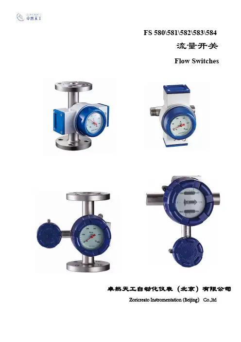
卓然天工自动化仪表(北京)有限公司 Zoricreato Instromentation (Beijing) Co.,ltdF S580\581\582\583\584流量开关Flow Switches一、概述F S58系列流量开关,可对各种液体流量进行监测和开关信号控制。
独特的结构设计,准确可靠的性能,广泛的应用于管道中大、中、小型设备的冷却、润滑系统中。
例如:发电机组、冷/热轧机、压缩机、轴封水、冷却系统等。
任意设置报警点/任意可调。
F S580系列/内管螺纹内管螺纹: 1/2". 3/4". 1-1/4". 1-1/2". 2". 2-1/2" 测量结构:锥管/靶式、喷嘴/靶式指示器形式:M1、 M2、M3、M4、M5流量开关设置:低流量报警/高流量报警;可独立选择低或高,也可同时选择低和高。
F S581系列外管螺纹: 1/2". 3/4". 1-1/4". 1-1/2". 2". 2-1/2" 测量结构:锥管/靶式、喷嘴/靶式指示器形式:M1、 M2、M3、M4、M5流量开关设置:低流量报警/高流量报警;可独立选择低或高,也可同时选择低和高。
F S582系列法兰:DN15 . 20 . 25 . 32 . 40 . 50 . 65 (口径)测量结构:锥管/靶式、喷嘴/靶式指示器形式:M1、 M2、M3、M4、M5流量开关设置:低流量报警/高流量报警;可独立选择低或高,也可同时选择低和高。
F S583系列法兰:DN80 . 100 .125 . 150 . 200 . 250 (口径)测量结构:锥管/靶式、喷嘴/靶式指示器形式:M1、 M2、M3、M4、M5流量开关设置:低流量报警/高流量报警;可独立选择低或高,也可同时选择低和高。
F S584系列(插入式)法兰: DN150 (口径)测量结构:靶式指示器形式:M1、 M2、M3、M4、M5流量开关设置:低流量报警/高流量报警;可独立选择低或高,也可同时选择低和高。
FSW300系列流量开关说明书

FSW300 Series Starts at
£90
Adjustable Switch Point
Low Pressure Drop
Economical
Field Installation for 1⁄2 to 8" Pipes
Instant Response
Dimensions (Excluding Paddle or Tee): 114 x 38 x 89 mm (4.5 x 1.5 x 3.5")
SPECIFICATIONS FSW302, 303, 304
Max Pressure: 25 bar (362 psi)
Max Process Temp: 110°C (230°F)
4.9 to 6.8 (1.3 to 1.8) 9.5 to 12.1 (2.5 to 3.2) 10.6 to 14.8 (2.8 to 3.9)
Comes complete with operator’s manual. Ordering Example: FSW305-G, inline flow switch, 1⁄2" PVC tee connection, 70A-2, audible alarm, £90 + 10.75 = £100.75
Comes complete with operator's manual.
Ordering Example: FSW301, insertion style flow switch and 70A-2, fast pulse tone alarm, £90 + 10.75 = £100.75
B-75
威卡(WIKA)电子流量开关FSD-3型说明书
流量威卡 (WIKA) 数据资料 FL 80.01第 1/7 页电子流量开关带显示,用于液体介质FSD-3 型数据手册中显示了同类产品:带显示的电子压力开关,PSD-4 型,具体情况请参见数据手册 PE 81.86带显示的温度开关,TSD-30 型,具体情况请参见数据手册 TE 67.03带显示的液位开关,LSD-30 型,具体情况请参见数据手册 LM 40.01威卡 (WIKA) 数据资料 FL 80.01 ∙ 12/2017应用■控制冷却润滑系统 ■监控冷却回路控制过滤器单元■ ■泵的空转保护产品特性■ ■支持流量、温度和诊断的开关和模拟输出可靠监测液体介质的流量■通过自带数显仪轻松实现参数化 ■无运动部件,无磨损描述在设计和功能上获得奖项PSD-30 曾摘得 “iF 产品设计奖” 桂冠,这充分证明威卡 (WIKA) 开关产品系列的成功的设计和出色的功能已得到专业认可。
坚固耐用的 LED 显示屏支持 9 mm 高(目前最大的)的字符显示,且字符稍有倾斜,使得用户能远距离轻松读取。
简单直观的 3 键式菜单导航系统,无需其它辅助设备,并且菜单导航符合 VDMA 标准。
无磨损FSD-3 基于量热测量原理,无任何运动部件,可实现无磨损测量。
液体介质流量监测FSD-3 能可靠监测液体介质流量,有助于确保过程安全。
当流量高于或低于设定值时,FSD-3 的开关输出会激活下游的调节器或控制装置,从而防止由于泵、刀具和主轴减速而导致的人员伤害或生产受损。
温度监测FSD-3 还能监测介质温度并输出相关数据,无需其它测量设备。
诊断功能当检测到传感器缺陷时,可选的诊断功能能可靠地输出报警信号,以及时触发下游安全功能。
电子流量开关FSD-3型测量范围流速水: 5...150 cm/s油: 3...300 cm/s出厂默认设置是以水作为介质进行的。
建议通过菜单根据系统的最小/最大流量来进行此调节。
温度(可选项)-20 ... +85 °C (-4 ... +185 °F)数显14 段 LED,红色,4 位,字符尺寸 9mm(0.35 英寸)显示器可电子控制转动 180°输出信号模拟信号(可选)4 ... 20 mA电路标度温度(可选项)零点:-20 ... +5 °C (-4 ... +41 °F)最终值:60...85 °C (140 ...185 °F)开关阈值开关动作点 1 和开关动作点 2 可单独调节开关功能常开,常闭,窗口,回差自由调节开关电压电源 - 1V开关电流最大 250 mA接通偏移10 秒稳定时间流速 (0 ...100 %, 100...0 %): 6 秒流速 (50...100 %, 100...50 %): 4 秒温度 t90:4 秒温度 t63:2 秒载荷模拟信号 4...20 mA: ≤ 0.5 kΩ使用寿命1亿次开关周期页码 2/7威卡(WIKA)数据资料 FL 80.01 ∙ 12/2017威卡(WIKA )数据资料 FL 80.01 ∙ 12/2017页码 5/7供电电压供电电压电源DC 15 ... 35 V电流消耗■有模拟信号的开关输出:175 mA ■无模拟信号的开关输出:150 mA 总电流消耗最大 650mA ,包括开关电流非重复性流量(5...100 cm/s): ≤ 2 cm/s 温度: ≤ 0.5 K标准条件下的准确度流速 (5 ... ≤ 100 cm/s): ≤ 测量范围最终值 ±5 %流速 (> 100 ...175 cm/s): ≤ 测量范围最终值 ±10 %温度: ≤ ±1,5 K包括非线性精度、回差、零点偏移和满量程偏差(与根据 IE C 61298-2 测得的误差值对应)。
宝德8032流量开关说明书
8032 型分体式流量控制器操作手册目 录8032 型分体式流量控制器1安全说明 (2)1.1使用 (2)1.2安装调试注意事项 (2)1.3符合的标准 (2)2产品说明 (3)2.1结构 (3)2.2测量原理 (3)2.3标准供货 (3)2.4附件 (3)3技术参数 (4)4安装 (5)4.1安装建议 (5)4.2安装 (5)4.3电气连接 (5)4.3.1连接器 (5)4.3.2控制器M12连接器接线 (6)5编程 (7)5.1一般建议 (7)5.2功能 (7)5.3编程键 (7)5.4缺省设置 (7)5.5正常模式 (8)5.6可能的开关模式 (8)5.7校正模式 (9)5.8模拟模式 (10)6维护 (11)6.1清洗 (11)6.2故障信息 (11)7附录 (12)7.18032易连接举例 (12)7.28032控制器标签说明 (12)7.3流量-流速-通径图 (13)1.1使用8032控制器仅适用于测量液体的流量制造方不负任何责任关于该仪表的保证条款也将无效1 安全说明始终遵守标记有该符号的安全说明不允许用户接触仪表内部的电缆请与贵地区的宝得分销商联系1.2安装调试注意事项则不能防电击只能使用化学性质兼容的产品来清洁该仪表避免该控制器受电磁干扰1.3安装调试注意事项电磁兼容性(EMC): EN 50 081-1(1992), 50 082-2(06-1995)安全性: EN 61 010-1(1993,A2-1995)抗振性: EN 60068-2-6(09-1995)抗震性: EN 60068-2-27(1987)8032 型分体式流量控制器2 产品说明2.1结构该分体式流量控制器为电子模块并且与远程的流量传感器相连激活报警器或建立一个控制回路2.2测量原理该8032型分体式流量控制器检测远程流量传感器的脉冲信号该脉冲信号的频率与流量成正比(f=K.Q,f为频率Hz Q为流量:升/秒)´ý½ÓÏß5针M12插孔连接器待接线4针M12插头连接器3 技术参数一般特性重复性防护等级(外壳)电气特性安装等级绝缘强度电源最大电流消耗极性反向保护晶体管输出短路保护推荐的电缆类型脉冲输出电气连接NPN/PNP 输出式材质外壳材质前面板支架环境环境温度相对湿度尺寸(mm)0.4%连接器插好并固紧时IP6522300VAC与远程传感器有关:750mA不带负载最大700mA ×î´ó30VDC ¿ØÖÆÆ÷µçÔ´µçѹ¾§Ìå¹ÜÊä³öʽÓÐÆÁ±ÎµçÀÂ远程传感器连接电缆最大导线截面积0.5mm2频率范围:2-400Hz 脉冲输出5针M 12插孔连接器不在标准供货范围之内P VC <80%8032 型分体式流量控制器远程传感器804080208030其它电源18-30 VDC 12-30 VDC 12-30 VDC min.12 VDC max.30 VDC5针M124针M124,5 V < U1 < 5 V 0 V < U2 < 0,5 V54.262128013.54.1安装建议4 安装-选择合适的支架位置- 如图所示将控制器插入支架中强酸或浓酸碱类 脂肪族酮类氧化剂和氯化物请与宝得分销商联系始终确认切断电源采用:- 工作温度高于+80¾-¹ýÂ˲¨ºÍÎÈѹµÄ- 1A 保险4.3电气连接5针M 12插孔连接器不在标准供货范围内订货号不在标准供货范围内参见4.3.25编程4.3.2M12连接器接线接收器+电源(如PLC )针脚1234M 12电缆可按需提供针脚编号与导线颜色之间的关系订货号438 680µ¼ÏßÑÕÉ«×Ø°×À¶ºÚ»Ò8032 型分体式流量控制器(*)为防止电磁干扰并将该电缆的两端分别接到同电位的地5 编程5.1一般建议记住您设置的所有参数都可能会影响工艺过程5.2功能该仪表有三种工作模式从正常模式可进入校正模式和模拟模式单位在线校正滤波器模拟方式输入一个理论流量值来测试校正模式中设置的参数5.3编程键显示开关输出状态确认所选功能选择字符显示测量值和设定值4位字母数字混合显示0-95.4缺省设置首次通电时流量单位O LO D EL滤波器棒图下限棒图上限l/s迟滞模式OLO OHIOLO OHI OLO OHI OLO OHI85.5正常模式返回前一个功能同时按这些键显示实际流量显示下限值(OLO )显示上限值(OHI)至下一个功能5.68032可能的开关模式迟滞模式检测到一个限值就改变状态(流量增加时:量减少时:检测下限(OLO))Ö»Óе±ÏÞÖµ(OHL 或OLO )超过了D E L 延时时间后流量和开关模式不同时5 编程5.7校正模式改变流量单位(1/s1/h m3/h Ga/min至下一个菜单也被参见第8-下限(OLO)和上限 (OHI)开关限值-开关模式是否反向 (INV,参见第8页)-开关动作前的延时 (DEL,单位为秒)确定的最小(BGLO)(BGHI)值将8032控制器与阀门相连接显示器显示<<YES TEAC>>时按键并打开阀门:这时显示器上的<<TEAC>>信号闪烁再按键返回(END)正常模式显示温度0表最高的滤波等级108032控制器设置:将校正模式中设置的数值填在以下的表格中:5 编程单位模式限值反向延时滤波棒图日期签名迟滞模式:窗口模式:5.8模拟模式扩展板(EXT)功能未用返回前一个菜单至下一个菜单输入一个流量值(S IM )并按ENTER 键后测试开关限值UNIT K FAC Win.**OLO OHI Yes No DEL(s)FILTBGLO BGHI8032 型分体式流量控制器K 系数Hyst.* *同时按 键可移动小数点。
SP-G 液体流量开关 1 9A2E21 说明说明书
19A2E21ManualSP-G 15 SP-G 2029A2E21FunctionThe SP-G liquid flow switch is designed for controlling and monitoring fluid flows. The function is based solely on the flow of the liquid and is not affected by the system’s static pressure; however, the system does require a basic pressure in excess of 1 bar.The switch is customised for applications where alarms for low flows are required while large flows can pass through without any increased fall in pressure. The switch has a variable through-flow area that increases as the flow increases.The through-flowing fluid lifts a spring-loaded pressure plate. The shaft on which the plate is mounted is mechanically connected to a lever that actuates a built-in micro-switch. Thedimension of the pressure plate controls the signal point. The contact changes positions at the ordered alarm point, which can be selected from 1.5 l/m to 30 l/m.If, for example, the switch is used to start a high-pressure pump or to open a valve, the flow may be allowed to increase significantly across the alarm point since the tray is lifted higher and the through-flow area increases continuously. Conversely, the switch can be installed in a flow system for e.g. protection against the dry running of a pump. Normally, at high flows, the fall in pressure across the switch is negligible. Nevertheless, the low flow alarm can be set to as low as 1.5 l/min since the through-flow area continues to decrease as the flow decreases and the plate moves downwards.Those parts that come into contact with the liquid are manufactured in dezincification-resistant brass, Teflon and stainless steel. Synthetic rubber gaskets.SP -G designsTwo different connection dimensions of the SP-G model are available: SP-G15 ½” female and SP-G20 ¾” male.The SP-G has a built-in micro-switch with alternating contact function.The outlet side can be rotated 90° or 180°, providing a number of alternative mountings for horizontal or vertical piping.SP-G mounting examples with inlet and outlet in different directions39A2E21SP -G installation instructions∙ Refer to the type plate and check that the desired alarm point in l/min and the liquid (e.g. water or oil) are correct.∙ Check that the amperage does not exceed the maximum load according to the switch contact specifications.∙ Make sure that the arrow on the switch housing is pointing in the direction of the flow. ∙ Make sure not to exceed the maximum operating pressure of 25 bar.∙ Make sure the liquid temperature does not fall below the minimum temperature or exceed the maximum temperature: –20 °C to +90 °C (optional +120 °C).∙ Mount the switch in the desired position. The outlet side may be rotated 90° or 180°. ∙ If there is a risk of freezing, the outlet side connection should point downwards in order to allow for drainage.∙ No straight sections are required upstream or downstream of the switch. ∙ Install a dirt filter at the front if there is a risk of clogging.SP -G specificationsFlow range:0 – 3.5 m/s. Max. flow limited by pump capacity and acceptable pressure drop.Alarm point: Min. 1.5 l/min, max. 30 l/min. Connections: SP-G15: ½” BSP female SP-G20: ¾” BSP male Pressure:Max. 25 bar Min. 1 barMax. fluid temperature: 90 °C (optional 120 °C) Min. liquid temperature: –20 °C Protection class: IP 43 (NEMA 3R) with M16 GR cable gland included. Wetted materials:Dezincification-resistant brass, stainless steel 316 and PTFE Nitrile (HNBR)/EPDM seals. Optional FPM (Viton) Enclosure material: Polycarbonate (Lexan®)Micro-switch:SPDT, 1-pole 2-way connector. In the standard design, the contact surfaces are silver-plated. Max. load 250 V/8 A Nominal, 250 V/10 A Thermal. Max. hysteresis: +/- 10%Pressure drop:Approx. 0.03 bar/1.5 l/min49A2E21Electrical dataSP-G switchContact function 1-pole, 2-wayDimensions and weightEletta Flow AB Box 5084SE-141 05 Kungens Kurva, Sweden08 – 603 07 70******************Proprietary RightsThis manual contains confidential technical data, including trade secrets and proprietary information, which are the property of Eletta Flow AB, Sweden.Any changes or alterations to downloaded or printed Eletta original documentation such as manuals, drawings, leaflets, newsletters, etc, are not permitted without writtenpermission from Eletta Flow AB, Sweden. This data is only disclosed to you under the permission of limited use within your company. Use for manufacturing or processing is not permitted. Any other use of data and information is strictly prohibited without prior written permission from Eletta Flow AB, Sweden.SP-G 15 Weight: 1.3 kgSP-G 20 Weight: 1.3 kg。
PF3WB PF3WC PF3WS PF3WR数字流量开关-多功能型说明书
Page 1 of 3Instruction ManualDigital Flow Switch – Manifold type PF3WB / PF3WC PF3WS / PF3WRThe intended use of thedigital flow switch manifoldis to monitor and adjust fluid flow to a device while connected to the IO-Link protocol.These safety instructions are intended to prevent hazardous situations and/or equipment damage. These instructions indicate the level of potential hazard with the labels of “Caution,” “Warning” or “Danger.”They are all important notes for safety and must be followed in addition to International Standards (ISO/IEC) *1), and other safety regulations. *1)ISO 4414: Pneumatic fluid power - General rules relating to systems. ISO 4413: Hydraulic fluid power - General rules relating to systems.IEC 60204-1: Safety of machinery - Electrical equipment of machines. (Part 1: General requirements)ISO 10218-1: Manipulating industrial robots -Safety. etc.• Refer to product catalogue, Operation Manual and Handling Precautions for SMC Products for additional information. • Keep this manual in a safe place for future reference.CautionCaution indicates a hazard with a low level of risk which, ifnot avoided, could result in minor or moderate injury.WarningWarning indicates a hazard with a medium level of riskwhich, if not avoided, could result in death or serious injury.DangerDanger indicates a hazard with a high level of risk which, ifnot avoided, will result in death or serious injury.Warning• Always ensure compliance with relevant safety laws and standards.• All work must be carried out in a safe manner by a qualified person in compliance with applicable national regulations.• This product is class A equipment intended for use in an industrial environment. There may be potential difficulties in ensuring electromagnetic compatibility in other environments due to conducted or radiated disturbances.• Refer to the operation manuals on the SMC website (URL: https:// ) for more safety instructions.Warning• Special products (-X) might have specifications different from those shown in the following section. Contact SMC for specific drawings.2 Specifications2.1 Manifold Common Specifications2.2 IO-Link specifications (for PF3W7##-L flow switch)• Refer to the PF3WB Operation Manual and the Operation Manual for the PF3W7, PF3W7-L or PF3W5 series on the SMC website (URL: https:// ) for more Specification details.3.1 PF3WB type ManifoldPart DescriptionSupply(Supply unit)This unit supplies the fluid from the supply side main piping to the application.Flow adjustment valve and stop valve can be combined to comprise the equipment.• The supply unit is not suitable for a flow switch. Return(Return unit)This unit returns the fluid exhausted from the application.Flow adjustment valve and stop valve can be combined to comprise the equipment.Flow switch The flow switch displays or outputs the flow rate when flow is applied.• Applicable to integrated display type / remote sensor type (temperature sensor type can be selected).• IO-Link compatible (Integrated display type PF3W7##-L only).• Cannot be used for the supply unit.Display The integrated display type displays flow rate, set value and error codes.The remote type displays POWER indicator and FLOW indicator.For display, refer to the Operation Manual.(Display integrated type: PF3W7, remote sensor type sensor: PF3W5)Connector This is for connecting the lead wire.PartDescriptionLead wire with M8 connectorLead wire to supply power to and obtain output signals from the flow switchFlow adjustment valveOrifice mechanism to adjust the flow rate.• The flow adjustment valve is not suitable for applications which require constant adjustment of flow rate.• This valve is not suitable for stopping the flow. • Applicable to both the supply and return unit. Flow adjustment knob This knob is for adjusting the flow rate. Lock ringThis is used for holding the flow adjustment valve.Stop valveThis is the mechanism for stopping the flow rate. ∗: Not suitable for adjusting the flow rate. ∗: Applicable to supply/return unit.Stop valve handleThis handle is for stopping the flow rate. When the handle is rotated by 90°, it is possible to stop the flow rate.AttachmentTo connect the piping of the supply/return units. Main pipingTo connect the piping of the manifold body. Open or close cannot be selected.• PF3WC series is not applicable to “Close”. • It is not possible to change the main piping after ordering.ORIGINAL INSTRUCTIONSModel PF3WBPF3WCPF3WSPF3WRManifold specifications Integrated type Remote type Arrangement 1 to 10 stationSupply or Return: 1 to 5 station1 to 10 station1 to 10 stationU n i t Rated flow range 0.5 to 4 L/min, 2 to 16 L/min, 5 to 40 L/min Supply unit construction With flow adjustment valve / stop valve- Return unit construction Flow switch,flow adjustment valve,stop valve-Flow switch, adjustment valve, stop valveF l u i d Applicable fluid Water and ethylene glycol solution with aviscosity of 3 mPa •s(3 cP) or less Fluid temp. 0 to 90 o C (No freezing and condensation)P r e s s u r e Operating pressure range 0 to 1 MPa Proof pressure 1.5 MPaPressure loss Refer to graph for pressure lossE n v i r o n m e n tEnclosure IP65Operating temp. range 0 to 50 oC (No freezing and condensation)Operating humidity range Operation, Storage: 85%R.H. (No condensation)Materials in contact with fluidPPS, SUS304, FKMGrease free P i p i n g p o r tMain piping 1 inch Attachments 3/8, 1/2, 3/4 inch•The PF3WB type manifold is shown .The individual parts of the PF3WC, PF3WS and PF3WR are the same.4.1 InstallationWarning•Do not install the product unless the safety instructions havebeen read and understood.•Use the product within the specified operating pressure andtemperature range.•Tighten to the specified tightening torque.If the tightening torque is exceeded the mounting screws, brackets andthe product can be broken. Insufficient torque can cause displacementof the product from its correct position.•Do not drop, hit or apply excessive shock to the product.Otherwise damage to the internal parts can result, causing malfunction.•Do not pull the lead wire forcefully, and do not lift the product bypulling the lead wire (tensile force 49 N or less).4.2 EnvironmentWarning•Do not use in an environment where corrosive gases, chemicals, saltwater or steam are present.•Do not use in an explosive atmosphere.•Do not expose to direct sunlight. Use a suitable protective cover.•Do not install in a location subject to vibration or impact in excess ofthe product’s specifications.•Do not mount in a location exposed to radiant heat that would result intemperatures in excess of the product’s specifications.•Do not use the product in places where there are cyclic temperaturechanges.Heat cycles other than ordinary changes in temperature can adverselyaffect the inside of the product.4.3 Mounting•Never mount the product in a location where it will be used as a support.•Mount the product so that the fluid flows in the direction indicated bythe arrow on the product label or on the product body.•Check the flow characteristics data for pressure loss and the straightinlet pipe length effect on accuracy, to determine inlet pipingrequirements.•Do not sharply reduce the piping size.•The monitor with integrated display can be rotated. It can be set at 90ointervals clock and anticlockwise, and also at 45o and 225o clockwise.Rotating the display with excessive force will damage the end stop.•When a stop valve is mounted, rotate the monitor after closing the stopvalve handle.Rotating the monitor with excessive force with the stop valve open, themonitor and stop valve will interfere with each other, causing damage(refer to the figure below).4.4 Direct mounting (PF3W704 / 720 / 740)•When mounting the product, mount it to a panel with screws(equivalent to M6) using the mounting holes provided.•Mounting plate thickness should be approximately 3 mm.•Screws and nuts must be prepared by the user.The PF3WB uses 6 mounting screws, and the PF3WC, PF3WS and4.5 PipingCaution•Before connecting piping make sure to clean up chips, cutting oil, dustetc.•When installing piping or fittings, ensure sealant material does notenter inside the port.•Eliminate any dust left in the piping using an air blow before connectingthe piping to the product.•Ensure there is no leakage after piping.•When connecting piping to the product, hold the piping with a wrenchon the metal part of the piping (piping attachment) and main port of themain piping, which is integrated into the piping.•Using a spanner on other parts may damage the product.In particular, do not let the spanner come into contact with the M8connector. The connector can be easily damaged.After hand tightening, apply a spanner of the correct size to thespanner flats on the product, and tighten it for 2 to 3 rotations, to thetightening torque shown in the table below.If the tightening torque is exceeded, the product can be damaged. Ifthe correct tightening torque is not applied, the fittings may becomeloose.Nominal Thread size Tightening torque Width across flatsRc (NPT) 3/8 15 to 20 N•m 20.9 mmRc (NPT) 1/2 20 to 25 N•m 23.9 mmRc (NPT) 3/4 28 to 30 N•m 29.9 mmRc (NPT) 1 36 to 38 N•m 41.0 mm4.6 WiringCaution•Do not perform wiring while the power is on.•Confirm proper insulation of wiring.Poor insulation (interference from another circuit, poor insulationbetween terminals, etc.) can lead to excess voltage or current beingapplied to the product, causing damage.•Do not route wires and cables together with power or high voltagecables.Otherwise the product can malfunction due to interference of noise andsurge voltage from power and high voltage cables to the signal line.Route the wires (piping) of the product separately from power or highvoltage cables.•Keep wiring as short as possible to prevent interference fromelectromagnetic noise and surge voltage.Do not use a cable longer than 30 m. (IO-Link compatible device: 20m or less).•Ensure that the FG terminal is connected to ground when using acommercially available switch-mode power supply.•When an analogue output is used, install a noise filter (line noise filter,ferrite element, etc.) between the switch-mode power supply and thisproduct.4.7 Connector Wiring5 SettingsRefer to the Operation manuals on the SMC website(URL: https://) for the following Settings:Flow switch Setting and Function setting•Integrated display type: PF3W7•Integrated display type (IO-Link compatible): PF3W7-L•Remote type sensor: PF3W56.1 General MaintenanceCaution•Not following proper maintenance procedures could cause the productto malfunction and lead to equipment damage.•If handled improperly, compressed air can be dangerous.•Maintenance of pneumatic systems should be performed only byqualified personnel.•Before performing maintenance, turn off the power supply and be sureto cut off the supply pressure. Confirm that the air is released toatmosphere.•After installation and maintenance, apply operating pressure andpower to the equipment and perform appropriate functional andleakage tests to make sure the equipment is installed correctly.•If any electrical connections are disturbed during maintenance, ensurethey are reconnected correctly and safety checks are carried out asrequired to ensure continued compliance with applicable nationalregulations.•Do not make any modification to the product.•Do not disassemble the product, unless required by installation ormaintenance instructions.•How to reset the product after a power cut or when the power hasbeen unexpectedly removedWhen the flow switch is the integrated display type, the settings of theproduct are retained from before the power cut or de-energizing.The output condition also recovers to that before the power cut or de-energizing, but may change depending on the operating environment.Therefore, check the safety of the whole system before operating theproduct.7 Troubleshooting7.1 Error indication (PF3W7 Integrated display type)When using PF3W7 integrated display or PF3W5 remote sensorWhen PF3W7-L (IO-Link) is used in SIO modeNo. Name Wire colour Function1 DC(+) Brown 12 to 24 VDC2 N.C./ OUT2 White N.C. / Switch output 2 (SIO)3 DC(-) Blue 0 V4 OUT1 Black Switch output 1 (SIO)When PF3W7-L (IO-Link) is used as IO-Link deviceNo. Name Wire colour Function1 L+ Brown 18 to 30 VDC2 N.C./ OUT2 White N.C. / Switch output 2 (SIO)3 L-Blue 0 V4 C/Q BlackIO-Link data /Switch output 1 (SIO)∗: Wire colours are for the lead wire included with the PF3W7 series.Page 3 of 37.2 Error indication (PF3W5 Remote sensor type) If the error cannot be reset after the above measures are taken, or errors other than the above are displayed, please contact SMC.Refer to the Operation manual on the SMC website (URL: https:// ) for more detailed information about Troubleshooting.8 How to OrderRefer to the operation manual or catalogue on the SMC website (URL: https:// ) for How to order information.9 Outline Dimensions (mm)Refer to the Operation manual on the SMC website (URL: https:// ) for outline and mounting dimensions for the PF3WB, PF3WC, PF3WS and PF3WR.10.1 Limited warranty and Disclaimer/Compliance Requirements Refer to Handling Precautions for SMC Products.11 Product disposalThis product should not be disposed of as municipal waste. Check your local regulations and guidelines to dispose of this product correctly, in order to reduce the impact on human health and the environment.12 ContactsRefer to or www.smc.eu for your local distributor / importer.URL: https:// (Global) https:// (Europe) SMC Corporation, 4-14-1, Sotokanda, Chiyoda-ku, Tokyo 101-0021, Japan Specifications are subject to change without prior notice from the manufacturer. © 2021 SMC Corporation All Rights Reserved. Template DKP50047-F-085M。