
西门子自学教程——电机2
Accelerating and The magnetic attraction of the rotating magnetic field will Breakdown T orque cause the rotor to accelerate. As the motor picks up speedtorque decreases slightly until it reaches point B on the graph.As speed continues to increase from point B to point C torqueincreases until it reaches it’s maximum at approximately 200%.This torque is referred to as accelerating or pull up torque.Point C is the maximum torque a motor can produce. At thispoint a 30 HP motor will develop approximately 178.4 Lb-Ft oftorque. If the motor were overloaded beyond the motor’s torquecapability, it would stall or abruptly slow down at this point. Thisis referred to as breakdown or pullout torque.Full-Load T orque Torque decreases rapidly as speed increases beyondbreakdown torque (point C), until it reaches full-load torque ata speed slightly less than 100% synchronous speed. Full-loadtorque is the torque developed when the motor is operatingwith rated voltage, frequency and load. The speed at whichfull-load torque is produced is the slip speed or rated speedof the motor. Recall that slip is required to produce torque.If the synchronous speed of the motor is 1800 RPM and theamount of slip is 1.9%, the full-load rated speed of the motor is1765 RPM. The full-load torque of the 1765 RPM 30 HP motoris 89.2 Lb-Ft. NEMA design B motors are general purposesingle speed motors suited for applications that require normalstarting and running torque such as conveyors, fans, centrifugalpumps, and machine tools.Starting Current and Starting current is also referred to as locked rotor current,Full-Load Current and is measured from the supply line at rated voltage andfrequency with the rotor at rest. Full-load current is the currentmeasured from the supply line at rated voltage, frequency andload with the rotor up to speed. Starting current is typically 600-650% of full-load current on a NEMA B motor. Starting currentdecreases to rated full-load current as the rotor comes up tospeed.NEMA A Motor NEMA sets limits of starting (locked rotor) current for NEMAdesign B motors. When special load torque or load inertiarequirements result in special electrical designs that will yieldhigher locked rotor current (LRA), NEMA design A may result.This designation also cautions the selection of motor controlcomponents to avoid tripping protective devices during longeracceleration times or higher than normal starting current.NEMA C Motor Starting torque of a NEMA design C motor is approximately225%. A NEMA C, 1765 RPM, 30 HP motor will developapproximately 202.5 Lb-Ft of starting torque. Hard to startapplications such as plunger pumps, heavily loaded conveyors,and compressors require this higher starting torque. Slip andfull-load torque are about the same as a NEMA B motor. NEMAC applies to single speed motors from approximately 5 HP to200 HP.NEMA D Motor The starting torque of a NEMA design D motor is approximately280% of the motor’s full-load torque. A NEMA D, with a full-load rated speed of 1765 RPM, 30 HP motor will developapproximately 252 Lb-Ft of starting torque. Very hard to startapplications, such as punch presses, cranes, hoists, and oil wellpumps require this high starting torque. NEMA D motors haveno true breakdown torque. After initial starting torque is reachedtorque decreases until full-load torque is reached. NEMA Dmotors typically are designed with 5 to 8% slip or 8 to 13% slip. Multispeed and ASD These specialized motor designs are uniquely designed or (Adjustable Speed Drive)selected to specific load requirements. NEMA designclassifications are not applicable to these specialized motors. Soft Starts Various special configurations of motor controls are selectedwhen starting/accelerating torques must be more accuratelycontrolled, or when starting current must be limited. In thecases of part winding start or wye-delta start, the motorwindings must be designed with unique connections forthe special controls. In cases such as reduced voltageautotransformer or electronic soft starts, relatively standardmotors may be approved for these special applications.Review 51. A 30 HP motor with a 1.15 service factor can beoperated at ____________ HP.2. A motor with Class F insulation has a maximum____________ temperature rise.3. The starting torque of a NEMA B motor isapproximately ____________ % of full-load torque.4. ____________ torque refers to point on a torque curvewhere a motor is overloaded beyond the motor’s torquecapability, causing the motor to stall or abruptly slowdown.Derating FactorsSeveral factors can effect the operation and performance ofan AC motor. These need to be considered when applying amotor.Voltage Variation AC motors are designed to operate on standardized voltagesand frequencies. The following table reflects NEMA standards.A small variation in supply voltage can have a dramatic affecton motor performance. In the following chart, for example,when voltage is 10% below the rated voltage of the motor,the motor has 20% less starting torque. This reduced voltagemay prevent the motor from getting its load started or keepingit running at rated speed. A 10% increase in supply voltage,on the other hand, increases the starting torque by 20%. Thisincreased torque may cause damage during startup. A conveyor,for example, may lurch forward at startup. A voltage variationwill cause similar changes in the motor’s starting amps, full-loadamps, and temperature rise.Frequency A variation in the frequency at which the motor operates causeschanges primarily in speed and torque characteristics. A 5%increase in frequency, for example, causes a 5% increase in full-load speed and a 10% decrease in torque.Altitude Standard motors are designed to operate below 3300 feet.Air is thinner and heat is not dissipated as quickly above 3300feet. Most motors must be derated for altitude. The followingchart gives typical horsepower derating factors, but the deratingfactor should be checked for each motor. A 50 HP motoroperated at 6000 feet, for example, would be derated to 47 HP,providing the 40°C ambient rating is still required.Ambient T emperature The ambient temperature may also have to be considered. Theambient temperature may be reduced from 40°C to 30°C at6600 feet on many motors. A motor with a higher insulationclass may not require derating in these conditions.AC Motors and AC DrivesMany applications require the speed of an AC motor to vary.The easiest way to vary the speed of an AC induction motoris to use an AC drive to vary the applied frequency. Operatinga motor at other than the rated frequency and voltage has aneffect on motor current and torque.Volts per Hertz A ratio exists between voltage and frequency. This ratiois referred to as volts per hertz (V/Hz). A typical AC motormanufactured for use in the United States is rated for 460 VACand 60 Hz. The ratio is 7.67 volts per hertz. Not every motor hasa 7.67 V/Hz ratio. A 230 Volt, 60 Hz motor, for example, has a 3.8V/Hz ratio.Flux (Φ), magnetizing current (I M), and torque are all dependenton this ratio. Increasing frequency (F) without increasing voltage(E), for example, will cause a corresponding increase in speed.Flux, however, will decrease causing motor torque to decrease.It can be seen that torque (T = kΦI W) is directly affected by flux(Φ). Torque is also affected by the current resulting from theapplied load, represented here by I W. Magnetizing current (I M)will also decrease. A decrease in magnetizing current will causea corresponding decrease in stator or line (I S) current. Thesedecreases are all related and greatly affect the motor’s ability tohandle a given load.Constant T orque AC motors running on an AC line operate with a constantflux (Φ) because voltage and frequency are constant. Motorsoperated with constant flux are said to have constant torque.Actual torque produced, however, is determined by the demandof the load.T = kΦI WAn AC drive is capable of operating a motor with constant flux(Φ) from approximately zero (0) to the motor’s rated nameplatefrequency (typically 60 Hz). This is the constant torque range. Aslong as a constant volts per hertz ratio is maintained the motorwill have constant torque characteristics. AC drives changefrequency to vary the speed of a motor and changes voltageproportionately to maintain constant flux. The following graphsillustrate the volts per hertz ratio of a 460 volt, 60 Hz motor anda 230 volt, 60 Hz motor. To operate the 460 volt motor at 50%speed with the correct ratio, the applied voltage and frequencywould be 230 volts, 30 Hz. To operate the 230 volt motor at50% speed with the correct ratio, the applied voltage andfrequency would be 115 volts, 30 Hz. The voltage and frequencyratio can be maintained for any speed up to 60 Hz. This usuallydefines the upper limits of the constant torque range.Constant Horsepower Some applications require the motor to be operated abovebase speed. The nature of these applications requires lesstorque at higher speeds. Voltage, however, cannot be higherthan the rated nameplate voltage. This can be illustrated usinga 460 volt, 60 Hz motor. Voltage will remain at 460 volts for anyspeed above 60 Hz. A motor operated above its rated frequencyis operating in a region known as a constant horsepower.Constant volts per hertz and torque is maintained up to 60Hz. Above 60 Hz the volts per hertz ratio decreases, with acorresponding decrease in torque.Frequency V/Hz30 Hz 7.6760 Hz 7.6770 Hz 6.690 Hz 5.1Flux (Φ) and torque (T) decrease:Horsepower remains constant as speed (N) increases andtorque decreases in proportion. The following formula applies tospeed in revolutions per minute (RPM).Reduced Voltage and A NEMA B motor that is started by connecting it to the power Frequency Starting supply at full voltage and full frequency will developapproximately 150% starting torque and 600% starting current.AC drives start at reduced voltage and frequency. The motorwill start with approximately 150% torque and 150% current atreduced frequency and voltage. The torque/speed curve shiftsto the right as frequency and voltage are increased. The dottedlines on the torque/speed curve illustrated below represent theportion of the curve not used by the drive. The drive starts andaccelerates the motor smoothly as frequency and voltage aregradually increased to the desired speed. An AC drive, properlysized to a motor, is capable of delivering 150% torque at anyspeed up to speed corresponding to the incoming line voltage.The only limitations on starting torque are peak drive currentand peak motor torque, whichever is less.Some applications require higher than 150% starting torque.A conveyor, for example, may require 200% rated torque forstarting. If a motor is capable of 200% torque at 200% current,and the drive is capable of 200% current, then 200% motortorque is possible. T ypically drives are capable of producing150% of drive nameplate rated current for one (1) minute.If the load requires more starting torque than a drive candeliver, a drive with a higher current rating would be required.It is appropriate to supply a drive with a higher continuoushorsepower rating than the motor when high peak torque isrequired.Selecting a Motor AC drives often have more capability than the motor. Drivescan run at higher frequencies than may be suitable for anapplication. Above 60 Hz the V/Hz ratio decreases and themotor cannot develop 100% torque. In addition, drives can runat low speeds, however, self-cooled motors may not developenough air flow for cooling at reduced speeds and full load.Each motor must be evaluated according to its own capabilitybefore selecting it for use on an AC drive.Harmonics, voltage spikes, and voltage rise times of AC drivesare not identical. Some AC drives have more sophisticatedfilters and other components designed to minimizeundesirable heating and insulation damage to the motor.This must be considered when selecting an AC drive/motorcombination. Motor manufacturers will generally classify certainrecommended motor selections based on experience, requiredspeed range, type of load torque, and temperature limits. Distance Between Distance from the drive to the motor must also be taken into Drive and Motor consideration. All motor cables have line-to-line and line-to-ground capacitance. The longer the cable, the greater thecapacitance. Some types of cables, such as shielded cable orcables in metal conduit, have greater capacitance. Spikes occuron the output of AC drives because of the charging currentin the cable capacitance. Higher voltage (460 VAC) and highercapacitance (long cables) result in higher current spikes. Voltagespikes caused by long cable lengths can potentially shorten thelife of the AC drive and motor. When considering an applicationwhere distance may be a problem, contact your local Siemensrepresentative.Service Factor on AC Drives A high efficiency motor with a 1.15 service factor isrecommended when used on an AC drive. Due to heatassociated with harmonics of an AC drive, the 1.15 servicefactor is reduced to 1.0.Matching AC Motors to the LoadOne way to evaluate whether the torque capabilities of amotor meet the torque requirements of the load is to comparethe motor’s speed-torque curve with the speed-torquerequirements of the load.Load Characteristics T ables To find the torque characteristics a table, similar to the partialone shown below, can be used. NEMA publication MG 1 is onesource of typical torque characteristics.Calculating Load T orque The most accurate way to obtain torque characteristics ofa given load is from the equipment manufacturer. A simpleexperiment can be set up to show how torque of a givenload can be calculated. In the following illustration a pulley isfastened to the shaft of a load. A cord is wrapped around thepulley with one end connected to a spring scale. The torquecan be calculated by pulling on the scale until the shaft turnsand noting the reading on the scale. The force required to turnthe shaft, indicated by the scale, times the radius of the pulleyequals the torque value. It must be remembered that the radiusis measured from the center of the shaft. If the radius of thepulley and shaft were 1 foot, for example, and the force requiredto turn the shaft were 10 pounds, the torque requirement is 10Lb-Ft. The amount of torque required to turn the connected loadcan vary at different speeds.Centrifugal Pump At any point during acceleration and while the motor isoperating at full-load speed, the amount of torque producedby the motor must always exceed the torque required by theload. In the following example a centrifugal pump has a full-loadtorque of 600 Lb-Ft. This is equivalent to 200 HP. The centrifugalpump only requires approximately 20% of full-load torqueto start. The torque dips slightly after it is started and thenincreases to full-load torque as the pump comes up to speed.This is typically defined as a variable torque load.A motor has to be selected that can start and accelerate thecentrifugal pump. By comparing a 200 HP NEMA B motor curveto the load curve, it can be seen that the motor will easily startand accelerate the load.Screw Down Actuator In the following example a screw down actuator is used. Thestarting torque of a screw down actuator is approximately200% of full-load torque. Comparing the load’s requirement(200%) with the NEMA design B motor of equivalenthorsepower, it can be seen that the load’s starting torquerequirement is greater than the motor’s capability (150%). Themotor, therefore, will not start and accelerate the load.One solution would be to use a higher horsepower NEMA B motor. A less expensive solution might be to use a NEMA D motor of the same horsepower requirements as the load. A NEMA D motor would easily start and accelerate the load.The motor selected to drive the load must have sufficient torque to start, accelerate, and run the load. If, at any point,the motor cannot produce the required torque the motor will stall or run in an overloaded condition. This will cause the motor to generate excess heat and typically exceed current limits causing protective devices to remove the motor from the power source. If the overload condition is not corrected, or the proper motor installed, the existing motor will eventually fail.Review 61. A motor rated for 460 VAC operating on a supply of437 VAC (-5%) will have a negative ____________ %change in motor performance.2. Using the altitude derating table the “Derating Factors”section, a 200 HP motor operated at 5500 feet wouldbe derated to ____________ HP.3. The volts per hertz ratio of a 460 Volt 60 Hz motor is____________ V/Hz.4. When applying an AC motor to an AC drive a motorwith a ____________ service factor is recommended.5. If the radius of a pulley and shaft were 2 feet, andthe force required to turn the shaft were 20 pounds,the amount of torque required to turn the load is____________ Lb-Ft.EnclosuresRecall that the enclosure provides protection from contaminantsin the environment in which the motor is operating. In addition,the type of enclosure affects the cooling of the motor. There aretwo categories of enclosures: open and totally enclosed.Open Drip Proof (ODP)Open enclosures permit cooling air to flow through the motor.The rotor has fan blades that assist in moving the air throughthe motor. One type of open enclosure is the drip proofenclosure. The vent openings on this type of enclosure preventliquids and solids falling from above at angles up to 15° fromvertical from entering the interior of the motor and damagingthe operating components. When the motor is not in thehorizontal position, such as mounted on a wall, a special covermay be necessary to protect it. This type of enclosure can bespecified when the environment is free from contaminates.T otally Enclosed In some cases air surrounding the motor contains corrosive Non-Ventilated (TENV)or harmful elements which can damage the internal partsof a motor. A totally enclosed motor enclosure restricts thefree exchange of air between the inside of the motor and theoutside. The enclosure is not airtight, however, and a seal at thepoint where the shaft passes through the housing keeps outwater, dust, and other foreign matter that could enter the motoralong the shaft. The absence of ventilating openings means allheat dissipates through the enclosure by means of conduction.Most TENV motors are fractional horsepower. TENV motorsare used, however, for larger horsepower special applications.For larger horsepower applications the frame is heavily ribbedto help dissipate heat more quickly. TENV motors can be usedindoors and outdoors.T otally Enclosed The totally enclosed fan-cooled motor is similar to the TENV Fan Cooled (TEFC)except an external fan is mounted opposite the drive end ofthe motor. The fan provides additional cooling by blowing airover the exterior of the motor to dissipate heat more quickly. Ashroud covers the fan to prevent anyone from touching it. Withthis arrangement no outside air enters the interior of the motor.TEFC motors can be used in dirty, moist, or mildly corrosiveoperating conditions. TEFC motors are more widely used forintegral HP applications.Explosion Proof (XP) The explosion proof motor enclosure is similar in appearanceto the TEFC, however, most XP enclosures are cast iron. Theapplication of motors used in hazardous locations is subject toregulations and standards set by regulatory agencies such asthe National Electrical Code® and Underwriters Laboratoriesfor XP motors used in the United States.NEC® and National Electrical Code® are registered trademarks of theNational Fire Protection Association.Hazardous EnvironmentsAlthough you should never specify or suggest the type of location, it is important to understand regulations that apply to hazardous locations. It is the user’s responsibility to contact local regulatory agencies to define the location as Division I or II and to comply with all applicable codes. There are two divisions.Division IHazardous materials are normally present in the atmosphere. A division I location requires an explosion proof motor.Division IIAtmosphere may become hazardous as result of abnormal conditions. This may occur if, for example, a pipe breaks that is the conduit for a hazardous chemical. Classes and GroupsOnce the location is defined as hazardous the location is further defined by the class and group of hazard. Class I, Groups A through D are chemical gases or liquids such as gasoline, acetone, and hydrogen. Class II, Groups E, F , and G include flammable dust, such as coke or grain dust. Class III is not divided into groups. It includes all ignitable fibers and lints such as clothing fiber in textile mills.Class I Class II Class III Groups A-D Groups E-G Gasses and Liquids Flammable Dust Ignitable Fibers Gasoline Coke Dust Rayon Acetone Grain Dust Jute Hydrogen Metalic Dust I C D G s F e C e G n M In some cases it may be necessary for the user to define the lowest possible ignition temperature of the hazardous material to assure the motor complies with all applicable codes and requirements.MountingNEMA Dimensions NEMA has standardized frame size motor dimensions.Standardized dimensions include bolt hole size, mountingbase dimensions, shaft height, shaft diameter, and shaftlength. Existing motors can be replaced without reworkingthe mounting arrangement. New installations are easier todesign because the dimensions are known. Letters are usedto indicate where a dimension is taken. For example, the letter“C” indicates the overall length of the motor. The letter “E”represents the distance from the center of the shaft to thecenter of the mounting holes in the feet. The actual dimensionsare found by referring to a table in the motor data sheet andreferencing the letter to find the desired dimension.NEMA divides standard frame sizes into two categories: fractional and integral. Fractional frame sizes are designated 48 and 56 and include primarily horsepower ratings of less than one horsepower. Integral or medium horsepower motors are designated by frame sizes ranging from 143T to 445T. A “T” in the motor frame size designation of integral horsepower motors indicates the motor is built to current NEMA frame standards. Motors built prior to 1966 have a “U” in the motor framesize designation, indicated they are built to previous NEMA Standards.The frame size designation is a code to help identify keyframe dimensions. The first two digits, for example, are usedto determine the shaft height. The shaft height is the distance from the center of the shaft to the mounting surface. To calculate the shaft height divide the first two digits of the frame size by 4. In the following example a 143T frame size motor has a shaft height of 3½ inches (14 ÷ 4).The third digit in the integral “T” frame size number is the NEMA code for the distance between the center lines of the mounting bolt holes in the feet of the motor.The dimension is determined by matching the third digit in the frame number with a table in NEMA publication MG-1. It can be seen that the distance between the center lines of the mounting bolt holes in the feet of a 143T frame is 4.00 inches.IEC Dimensions IEC also has standardized dimensions which differ from NEMA.Many motors are manufactured using IEC dimensions. IECdimensions are shown in the following drawing.Mounting Positions The typical floor mounting positions are illustrated in thefollowing drawing, and are referred to as F-1 and F-2 mountings.The conduit box can be located on either side of the frame tomatch the mounting arrangement and position. The standardlocation of the conduit box is on the left-hand side of the motorwhen viewed from the shaft end. This is referred to as the F-1mounting. The conduit opening can be placed on any of the foursides of the box by rotating the box in 90° steps.With modification the foot-mounted motor can be mounted onthe wall and ceiling. T ypical wall and ceiling mounts are shownin the following illustration. Wall mounting positions have theprefix “W” and ceiling mounted positions have the prefix “C”. Mounting Faces It is sometimes necessary to connect the motor directly tothe equipment it drives. In the following example a motor isconnected directly to a gear box.C-face The face, or the end, of a C-face motor has threaded bolt holes.Bolts to mount the motor pass through mating holes in theequipment and into the face of the motor.D-flange The bolts go through the holes in the flange of a D-flange motorand into threaded mating holes of the equipment.Review 71. A type of open enclosure that prevents liquids andsolids falling from above at angles up to 15° fromvertical from entering the interior of the motor is an____________ ____________ ____________ .2. A type of enclosure that is closed and uses a fanmounted on the shaft to supply cooling is referred as___________ ____________ ___________ ____________.3. Gasoline is defined as a Class ____________ hazard.4. The NEMA dimension from the center of the shaftto the mounting surface is designated by the letter____________ .5. The letter ____________ in the motor frame sizedesignation indicates a motor is built to current NEMAstandards.6. The shaft height can be determined by dividing thefirst two digits of an integral frame designation by____________ .7. A motor intended to be mounted on the wall with theconduit box facing up and the shaft facing left is anAssembly ____________ .8. A ____________ motor has threaded bolt holes tomount a motor to another piece of equipment.Siemens MotorsSiemens manufactures a wide range of AC motors. Thefollowing information provides only an introduction to thesemotors. Contact your local Siemens representative for moreinformation on any of the motors discussed or other SiemensAC motors.Medallion™ Motors Medallion motors represent the newer family of Siemensenclosed motors. Medallion EPAct efficiency motors are highperformance motors designed to meet the requirements ofthe U.S. Energy Policy Act of 1992 (EPAct). EPAct efficiencymotors are available from 1 to 200 HP in both ODP and TEFCenclosures. Depending on the specific motor, EPAct efficiencymotors are wound for 900, 1200, 1800, or 3600 RPM whenused on a 230 or 460 volt power supply. Premium efficiencyMedallion motors are available from 1 to 400 horsepower.Depending on the specific motor, premium efficiency motorsare wound for 900, 1200, 1800, or 3600 RPM when used ona 230/460 (460 only above 20 HP) volt power supply. EPActand premium efficiency motors are also available for use onother voltage sources such as 575 volt systems. Contact yourSiemens representative for information and lead times.。
西门子Sinumerik ShopMill操作培训手册说明书
SinuTrainShopMill 让铣削更轻松培训手册• 2006.08 SINUMERIK2006年08月第4次修订版软件版本号:V06.04西门子股份公司版权所有没有明确的书面许可,不得翻印或传播本文献的内容,亦不得采用影印或将本文献内容制成胶片、磁带、磁碟、幻灯片或其它多媒体制品等方法对本文献加以翻印。
0作为入门指导手册,本文献由以下单位合作完成:西门子股份公司自动化与驱动集团运动控制系统部邮政信箱: 3180, D-91050Erlangen/德国以及R. & S. KELLER GmbHSiegfried Keller, Stefan Nover, Klaus Reckermann, Olaf Anders, Kai Schmitz邮政信箱:131663, D-42043 Wuppertal/德国订货号:6FC5095-0AA50-0RP2ShopMill培训手册前言如何更快地从图纸到工件?迄今为止,数控生产主要采用复杂、抽象的代码进行NC编程,因而只有专业人员才能对其进行操作。
但是实际上,由于每一位熟练工人都堪称专业人士,因而也能够利用传统机械加工中所积累的丰富经验处理最为棘手的任务-尽管采取的方法通常很不经济。
所以,有必要找到一种方法,使这些技术专家们能够有效地将其经验应用到NC机床生产中。
西门子公司推出的ShopMill工具,不但使操作人员省却了编码之苦,亦使他们拥有了新一代的 SINUMERIK 控制系统。
西门子提供的解决方案是:建立一个工作计划,而非一段程序。
通过建立与操作人员水平相当且包含具体操作要求的工作计划,ShopMill的用户能够将其专业知识真正运用到加工过程当中,同时亦不会荒废实际的技能。
由于ShopMill能够建立强大的集成式运行轨迹,即使最复杂的轮廓和工件亦可轻松制得。
因此:可借助 ShopMill 更加快捷地从图纸向工件转移!尽管ShopMill 简单易学,但本培训教程有助您更快更好地掌握ShopMill的各项功能。
西门子S120变频器操作讲义(内部工程师培训)
西门子S120变频器操作讲义目录1硬件简介 (10)1.1单轴控制单元(AC/AC) (13)1.1.1单轴控制单元CU310DP和CU310PN (13)1.1.2CU310DP和CU310PN结构图 (14)1.1.3单轴控制适配器CUA31功能 (14)1.1.4CUA31结构图 (15)1.1.5单轴驱动器(AC/AC)模块及连接方式 (16)1.2多轴控制单元CU320 (17)1.2.1CU320功能 (17)1.2.2CU320结构图 (18)1.2.3CU320_DRIVE-CLiQ连接方式 (19)1.2.4常用接口模块 (20)1.3多轴控制单元D435 (22)1.3.1D435功能 (22)1.3.2D435结构图 (23)1.3.3D435系统拓扑 (24)1.4单轴驱动单元(电机模块)PM340 (25)1.4.1书本型 (25)1.4.2装机装柜型 (25)1.4.3柜机型 (25)1.5馈电单元(电源模块) (26)1.5.1BLM基本型电源模块 (26)1.5.2SLM智能型电源模块 (27)1.5.3ALM主动型电源模块 (27)1.6多轴驱动单元(电机模块) (28)1.6.1书本型 (28)1.6.2装机装柜型 (29)1.6.3柜机型 (29)1.7CF卡 (30)1.7.1CF卡功能 (30)1.7.2CF卡订货号与版本的关系 (30)1.7.3CF卡使用注意事项 (31)2软件简介 (32)2.1选型配置软件SIZER (32)2.2调试软件STARTER (32)2.3编程、调试软件SCOUT (33)3调试先决条件 (34)3.1.1CU320_DRIVE-CLiQ连接方式 (34)3.1.2DC24V连接方式 (36)3.1.3参数的序号范围 (37)4在线连接调试 (39)4.1运行“STARTER”软件 (39)4.2建立项目 (39)4.3PC ÅÆS120在线(Online)连接 (40)4.3.1RS232串行连接 (40)4.3.2PROFIBUS DP连接 (42)4.3.3PCÅÆPLCÅÆS120连接 (43)4.4在线(Online)连接操作 (45)4.5恢复工厂设置 (46)4.6自动配置(Automatic Conf igration) (47)4.7自动配置上传后检查 (48)4.8在线(OnLine)同步比较(PC/PGÅÆS120) (49)4.9复制RAM to ROM (50)4.10RAM、CF卡(ROM)及Star ter的关系 (51)4.11系统拓扑状态图 (52)5馈电(Infeeds)单元调试 (53)5.1馈电单元(S_INF_02)接线图 (53)5.2打开馈电单元(S_INF_02)参数表 (54)5.3馈电单元(S_INF_02)上电准备 (55)5.4DC母排电阻制动设定 (56)5.4.1单轴驱动单元(电机模块)PM340 (56)5.4.2多轴驱动单元(电机模块) (56)5.5馈电单元上电(ON)操作 (57)6驱动(Drives)单元调试 (58)6.1打开驱动单元(VECTOR_04)参数表 (58)6.2驱动单元恢复工厂设置 (59)6.3驱动单元V/F模式试转检测 (59)6.4电机参数设定 (60)6.5关于电机温度传感器 (61)6.6选择控制模式 (62)6.7优化准备工作 (62)6.7.1优化硬件准备 (62)6.7.1.1各类连接正确 (62)6.7.1.2各类电源已送上 (62)6.7.1.3抱闸已打开 (63)6.7.1.4电机轴不带负载 (63)6.7.2运行模式确认 (63)6.8电机静态数据辨识(静态优化) (63)6.9电机动态数据辨识(动态优化) (64)6.10电机动态运行检查 (65)6.11数据复制RAM to ROM (65)6.12将S120参数上传到PC/PG (66)7状态、报警、故障监控 (67)7.1控制字、状态字监控 (67)7.2报警和故障监控 (67)7.3历史报警和故障记录查询 (67)7.4报警和故障屏蔽及反应 (68)8驱动装置硬件版本查询和升级 (69)8.1驱动装置硬件版本查询 (69)8.2驱动装置硬件版本升级 (69)9项目的压缩及解压缩 (71)9.1项目的压缩 (71)9.2项目的解压缩 (72)10控制面板(Control panel)使用 (73)10.1打开控制面板(Control panel) (74)10.2获取控制面板权利 (75)10.3整流单元启动(ON) (75)10.4运行条件允许(Enables) (75)10.5逆变器启动(ON) (75)10.6转速给定值(Setpoint) (75)10.7运行状态显示 (76)11趋势图(Trace)使用 (77)11.1记录变量选择 (78)11.2记录模式选择 (78)11.3采样周期设定 (79)11.4采样触发方式设定 (80)11.5启动趋势记录 (81)11.6趋势图的Y轴座标尺度统一 (82)11.7曲线数据存盘和打开 (84)12手动优化调试 (85)12.1速度环Kp、Tn优化 (85)12.2手动优化方法 (86)12.3速度环动态响应曲线分析 (87)13DP通讯变量连接 (90)13.1通讯方式 (90)13.2配置CU站号 (90)13.3各单元PZD通讯量设定 (91)13.4通讯变量连接 (93)13.4.1整流单元变量连接 (93)13.4.2逆变单元变量连接 (95)13.5将S120参数上传到PC/PG (97)13.6将PC/PG参数下载到S120 (97)14STEP 7软件编程 (98)14.1STEP 7 硬件状态 (98)14.2STEP 7 软件编程 (99)14.3运行记录 (102)15BOP20操作面板的使用 (103)15.1BOP20面板标识含意 (103)15.2BOP20面板按键功能 (104)15.3BOP20按键使用规则 (105)15.4参数设置 (108)15.4.1控制单元设定(01) (108)15.4.1.1恢复工厂设置 (108)15.4.1.2选择驱动模式 (108)15.4.1.3选择参数模式 (108)15.4.2驱动单元设定(02) (109)15.4.2.1选择参数模式 (109)15.4.2.2电机标准设置(检查) (109)15.4.2.3选择电机类型 (109)15.4.2.4马达参数设置(非SIEMENS电机) (110)15.4.2.5自动计算电机电磁参数 (110)15.4.2.6控制环模式选择 (110)15.4.2.7选择ON/OFF命令源 (111)15.4.2.8选择电动电位计上升/下降命令源 (111)15.4.2.96.频率设定值通道选择 (112)15.4.2.10上升/下降斜率时间 (112)15.4.2.11选择BOP显示内容 (112)15.4.2.12结束快速调试 (113)15.4.2.13数据存储 (113)15.4.3驱动单元优化(02) (113)15.4.3.1优化硬件准备 (113)15.4.3.1.1各类连接正确 (113)15.4.3.1.2各类电源已送上 (114)15.4.3.1.3抱闸已打开 (114)15.4.3.1.4电机轴不带负载 (114)15.4.3.2优化软件(参数)准备 (114)15.4.3.3电机静态数据辨识 (114)15.4.3.4电机动态数据辨识 (115)15.4.3.5返回到运行模式 (116)15.4.3.6返回到运行显示模式 (116)15.4.3.7数据存储 (116)15.4.4BOP电机试运行 (116)16数据组参数 (117)16.1功率部件组 (117)16.2电机组 (118)16.3编码器组 (123)16.4命令数据组 (124)16.5驱动数据组 (128)1硬件简介SINAMIC变频器是SIEMENS公司近年来推出的交流传动装置,将取代6SE70等老一代变频器。
西门子200系列PLC直流步进电机控制方法

直流步进电机plc控制方法系统功能概述:本系统采用PLC通过步进电机驱动模块控制步进电机运动。
当按下归零按键时,电机1和电机2回到零点(零点由传感器指示)。
当按下第一个电机运行按键时,第一个电机开始运行,直到运行完固定步数或到遇到零点停止。
当按下第二个电机运行按键时,第二个电机开始运行,运行完固定步数或遇到零点停止。
两电机均设置为按一次按键后方向反向。
电机运行时有升降速过程。
PLC输入点I0.0为归零按键,I0.1为第一个电机运行按键,I0.2为第二个电机运行按键,I0.3为第一个电机传感器信号反馈按键,I0.4为第二个电机传感器信号反馈按键。
PLC输出点Q0.0为第一个电机脉冲输出点,Q0.1为第二个电机脉冲输出点,Q0.2为第一个电机方向控制点,Q0.3为第二个电机方向控制点,Q0.4为电机使能控制点。
所用器材:PLC:西门子S7-224xpcn及USB下载电缆。
编程及仿真用软件为V4.0 STEP 7 MicroWIN SP3。
直流步进电机2个,微步电机驱动模块2个。
按键3个。
24V开关电源一个。
导线若干。
各模块连接方法:PLC与步进电机驱动模块的连接:驱动模块中EN+、DIR+、CP+口均先接3k电阻,然后接24V 电源。
第一个驱动模块CP-接PLC的Q0.0,DIR-接PLC的Q0.2,EN-接PLC的Q0.4第二个驱动模块CP-接PLC的Q0.1,DIR-接PLC的Q0.3,EN-接PLC的Q0.4注意:1、PLC输出时电压为24V,故和驱动器模块连接时,接了3k 电阻限流。
2、由于PLC处于PTO模式下只有在输出电流大于140mA时,才能正确的输出脉冲,故在输出端和地间接了200欧/2w下拉电阻,来产生此电流。
(实验室用的电阻功率不足,用200欧电阻时功率至少在24*24/200=2.88w,即用3w的电阻)3、PLC与驱动模块连接时,当PLC输出低电平时不能将驱动模块电平拉低,故在EN-和DIR-上接了200欧/2W下拉电阻驱动模块与电机接法:驱动模块的输出端分别与电机4根线连接电机传感器与PLC连接:传感器电源接24v,信号线经过240欧电阻(试验中两个470电阻并联得到)与24v电源上拉后,信号线接到PLC的I0.3和I0.4将各模块电源、地线接好。
(2024年)西门子G120变频器培训教程和配套PDF

故障代码识别
介绍G120变频器中常见 的故障代码及其含义。
2024/3/26
故障诊断方法
阐述如何通过操作面板 、指示灯等信息进行故
障诊断。
故障处理流程
提供针对不同故障的处 理方法,包括复位操作 、检查接线、更换部件
等。
17
预防措施与建议
给出减少故障发生的建 议,如定期检查、保养 维护、合理设置参数等
按控制方式分类
开环控制变频器和闭环控制变频器。
按功能分类
通用变频器和专用变频器。
2024/3/26
应用领域
变频器广泛应用于工业领域,如机械制造、石油化工、冶 金、纺织、造纸、食品等行业,用于实现电动机的调速、 节能和提高生产效率。
5
变频器性能指标与选型依据
2024/3/26
调速范围
指变频器输出的最低频率与最高 频率之比,反映了调速能力。
在G120变频器中,直接转矩控制通过先进的算法和高速的数字信号处理器实现。用户可以在变频器参数设置中 选择直接转矩控制模式,并根据需要调整相关参数,如转矩限幅、速度环增益等,以实现高性能的直接转矩控制 。
2024/3/26
20
多电机同步运行技术
2024/3/26
主从同步控制技术
主从同步控制技术是指多个电机中,以一个电机为主电机,其他电机为从电机。主电机的 速度或位置信号被实时地传递给从电机,从电机根据主电机的信号进行相应的调整,以实 现多个电机的同步运行。
01
02
03
参数分类
概述G120变频器中参数 的分类,如控制参数、电 机参数、应用参数等。
2024/3/26
参数设置流程
详细阐述如何进行参数设 置,包括选择参数、修改 参数值、保存设置等步骤 。
西门子PLC_电动机的顺序启动控制定时器.ppt
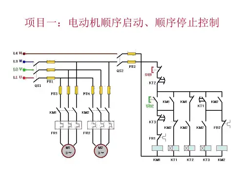
项目三:电动机顺序启动、逆序停止控制
项目三:电动机顺序启动、逆序停止控制 I/O分配表
输入
输出
输入继电 输入 作用 输出继电 输出
器
元件
器
元件
作用
I0.0
SB1 急停按 Q0.0
KM1 电机1运转交流接
钮
触器
I0.1
SB2 启动按 Q0.1
KM2 电机2运转交流接
钮
触器
项目三:电动机顺序启动、逆序停止控制
项目四:电动机延时启动、停止控制
I/O分配表
输入
输出
输入继电 输入 作用 输出继电 输出
器
元件
器
元件
作用
I0.0
SB1 停止按 Q0.0
KM1 电机运转交流接
钮触器I0.1SB2 启动按钮
项目四:电动机延时启动、停止控制
PLC接线图
SB1
KM1 FR
i0.0 Q0.0
SB2 i0.1
FU 220V
KM2 分断第二组电阻 交流接触器
KM3 分断第三组电阻 交流接触器电机
项目二: 三相绕线感应电动机转子绕组串电阻降压启动控制系统
PLC接线图:
SB1 SB2
24V
KM FR i0.0 Q0.0
KM1
Q0.1
i0.1
KM2
Q0.2
KM3
Q0.3
FU 220V COM
COM
项目二: 三相绕线感应电动机转子绕组串电阻降压启动控制系统
24V
COM
COM
项目四:电动机延时启动、停止控制
上节课需完成的项目: 项目一:电动机顺序启动、顺序停止控制 项目二:电动机的顺序启动、同时停止 项目三:电动机的顺序启动、逆序停止 项目四:电动机延时启动、停止控制
西门子PLC教程从入门到精通

Instruction List(指令表):是一种文本编程语言,通过指令名称和 操作码进行编程。
03
Function Block Diagram(功能块图):是一种图形化编程语言, 适合对功能块进行编程。
04
Structured Text(结构化文本):是一种高级文本编程语言,适合编 写复杂的算法和控制程序。
PLC的基本组成
01
02
03
04
05
中央处理单元 (CPU)
存储器
输入/输出接口( 电源模块 I/O…
通信接口
是PLC的核心部件,负责执 行用户程序和控制外部设 备。
用于存储用户程序、系统 程序和数据。
用于连接外部设备,实现 信号的采集和输出。
为PLC各部分提供稳定的电 用于与其他设备或控制器
源。
分布式控制中的应用
数据采集与监控
01
通过PLC实现生产线上各种传感器数据的采集和监控,实时掌握
生产状态。
远程控制
02
利用PLC的通讯功能,实现远程控制和监控,提高生产效率和安
全性。
故障诊断与排除
03
通过PLC对设备运行状态进行监测和分析,快速定位排除故障。PART 06
西门子PLC的发展趋势与 未来展望
电机速度调节
通过PLC调节电机输入电压或电流,实现电机速度的精确控制。
电机保护功能
利用PLC的输入输出端口,监测电机的运行状态,实现过载、短路 等故障保护。
过程控制中的应用
压力控制
利用PLC对压力传感器数据进行处理,实现 压力的自动调节和控制。
温度控制
通过PLC与温度传感器配合,实现温度的自 动调节和控制。
西门子PLC自学教程(从入门到精通)
软件编程规范与技巧
编程技巧
编程规范:遵循结构化编程 、模块化设计原则,编写清
晰易懂的程序。
01
02
03
合理使用中间变量和临时寄 存器,提高程序可读性和可
维护性。
采用循环结构和子程序调用 ,简化程序结构,提高运行
效率。
04
05
对关键代码段进行注释和说 明,方便后期维护和调试。
系统调试流程及注意事项
自动化生产线调试结果展示与 总结
展示生产线运行过程中的各 项参数监控界面
总结调试过程中遇到的问题及 解决方法
调试结果展示与总结
01
02
03
分析系统性能及优化方向
智能楼宇环境监控调试结果展示 与总结
展示环境参数实时监测界面及设 备控制界面
调试结果展示与总结
总结调试过程中遇到的问题 及解决方法
分析系统性能及优化方向
实例分析
通过实例分析,加深对梯形图编程语 言的理解和应用。
编程规则与技巧
学习梯形图的编程规则,如并联、串 联、置位、复位等,并掌握一些编程 技巧,如使用中间变量、避免双线圈 输出等。
指令表(STL)编程语言介绍
1 2 3
指令表基本概念
了解指令表的组成元素,如操作码、操作数、注 释等。
编程规则与技巧
学习指令表的编程规则,如赋值、比较、逻辑运 算等,并掌握一些编程技巧,如使用立即数、间 接寻址等。
实例分析
通过实例分析,加深对指令表编程语言的理解和 应用。
顺序功能图(SFC)编程语言介绍
顺序功能图基本概念
了解顺序功能图的பைடு நூலகம்成元素,如步、转换条件、动作等。
编程规则与技巧
学习顺序功能图的编程规则,如选择序列、并行序列、跳 转等,并掌握一些编程技巧,如使用局部变量、优化转换 条件等。
西门子培训幻灯片第2讲
• 出现如上:选择masterdrives vc(cuvc)(6se70变频器);unit 出现如上:选择masterdrives vc(cuvc)(6se70变频器);unit 变频器); version(这个非常重要,必须和实际的变频器一致, version(这个非常重要,必须和实际的变频器一致,实际变频器的 版本可从r069得知,若实际变频器的版本高于正在使用的, r069得知 版本可从r069得知,若实际变频器的版本高于正在使用的,那就重新 安装更高版本的软件); );bus address默认情况是 默认情况是0 安装更高版本的软件);bus address默认情况是0 ,可察看参数 P700,然后ok ok出现如下画面 P700,然后ok出现如下画面
• 出现如下画面:
• 选择菜单parameters出现如下
• 自由功能块是6se70里具有计算逻辑功能的功能块(见功能图) 自由功能块是6se70里具有计算逻辑功能的功能块(见功能图) 6se70里具有计算逻辑功能的功能块 115页 使用功能块类似于简单的plc编程。 plc编程 c2.pdf 115页,使用功能块类似于简单的plc编程。 • (1)包括计算和控制模块:加法器、减法器、乘法器、除法器、具 包括计算和控制模块:加法器、减法器、乘法器、除法器、 有滤波的绝对值发生器、信号反向、极限器、极限值监控器、 有滤波的绝对值发生器、信号反向、极限器、极限值监控器、最小值 最大值选择、计时单元、特性模块。 最大值选择、计时单元、特性模块。 • (2)逻辑模块:AND单元、OR单元、反向器、RS存储器等。 逻辑模块:AND单元 OR单元 反向器、RS存储器等 单元、 单元、 存储器等。 • 连接器:有开关量连接器和字连接器、双字连接器。(p357 c2.pdf) 连接器:有开关量连接器和字连接器、双字连接器。( 。(p357
西门子COMPACTdata低压大功率电机2
261LA8/1PQ8低压变频调速三相异步电动机(标准绝缘)
27
①不可能用于1LA8 407及以上的2极和4极以及1LA8 455及以上的6极电机③变频器带dv/dt 滤波器或正弦波滤波器*)1PQ8的数据与1LA8相同
②仅用于1LA8 407及以上的2极和4极以及1LA8 455及以上的6极电机
■也可提供400V Δ(订货号中电压标号9,选件号L1Y )·额定电压主690V
281LA8/1PQ8低压变频调速三相异步电动机(特殊绝缘)
*) 1PQ8的数据与1LA8相同
29
301LA4低压变频调速三相异步电动机(自扇冷)
*) 更大功率请咨询当地西门子办公室
1PQ4低压变频调速三相异步电动机
(强迫风冷)
*) 更大功率请咨询当地西门子办公室
31
32 1LA4中压变频调速三相异步电动机(自扇冷)
*) 4.16kV时的值
1PQ4中压变频调速三相异步电动机
(强迫风冷)
*) 4.16kV时的值
33。
西门子PLC 电动机顺序启动详解
SBI
KM1
iO-
QO.O
>T
O
SB2
KM2 FR2
lO.l
QO+1
SB3
24V
+・一
iO,2 C()M
FU 220V
COM -E□--H 9
2.1电动机的顺序启动、 同时停止
梯形图
10 J
Q O 0 HF
10.2
10<
Q0.0
0
<〉
14
Q0.0 10 0
<〉
2.2电动机的顺序启动、顺序停止
24V
COM s——< —
COM
项目三:电动机顺序启动、逆序停止控制
网枯1 圬络存题
I m/rg
4
I3
nO
9
/
T-
IN
• TON
1
PT
- 1BJ RS
hi坊?
珊5
T37
llh
TON
PT
W ■ ii -
OI
I—
MO f X
l)
H3 6
叻
Q0.1
/
MOO
IC7
叫I——U
T33
IN
TCH
iai- pn
100 ns
糊
继器
JJ
输电
出件 输元
1
流
KI
交
Tffl器
1 B
止 喺钮 机按
晒雜 机
.0
S
电
O
电
1*
2
流
M
交
2
3
运制
2 4T
2.2电动机的顺序启动、顺序停止