WiRE 4操作说明 中文
M型超声波FMU40 41 43超声液位测量 说明书
6
3.2 安装条件
液位测量的安装条件
2
3
4
1
5
7
1/6D
D
6
α
L
r
r
=Ltan
α 2
传感器
α
FMU40
11
FMU41
11
FMU43
6
L
γ
5m
0.48m
8m
0.77m
15m
0.79m
不可把传感器安装于罐顶的中心位置(3) 建议将传感器安 装在距罐壁 1 距离为罐直径的1/6处 使用防护罩 以防直接的日照或雨淋 不可安装于进料口的上方 (4) 在信号波束角 内 应避免安装任何装置 5 如限位开 关 温度传感器等 需要注意的是 对称装置如加热线 圈 挡板等 均有可能干扰测量 调整传感器使其垂直物料表面 7 在一个罐内不能安装两个超声波 因为两个信号会互相干 扰 可使用3dB波束角 来估算回波束和它的检测范围
008 距离/ 测量值
051
052
053
检查距离 抑制范围 开始抑制
显示D和L
-ok -太小 -太大 -未知 -手动
确认抑制范围
BD 盲 区
操作说明 操作说明描述了M型超声波的安装与调试 它包含了用于正常测量操作的所有功能 而且M型超声波提供附加功能用于测量点 的优化和测量值的转换 这些功能没有包含在这本操作手册中 你可以在35页浏览所有的功能 在操作手册BA240F/00/en中 你可以找到所有功能的详细描述 这些说明在提供的光盘中可以找到
60 AF G1½” 1½ NPT
Ø 39
FMU 43带滑动法兰
~86
65
78
ENDRESS+HAUSER Prosonic M
Alpha Wire M4220类型电缆说明书

Customer Specification PART NO. M4220ConstructionApplicable Specifications Environmental Alpha Wire | 711 Lidgerwood Avenue, Elizabeth, NJ 07207 Tel: 1-800-52 ALPHA (25742), Web: Diameters (In)1) Component 1 2 X 1 COAXa) Conductor 20 (7/28) AWG TC 0.038b) Insulation 0.0205" Wall, Nom. Polyethylene(PE) 0.079(1) Color(s)Cond Color Cond Color Cond Color1 NATURAL2 NATURAL2) Cable Assembly 2 Components Cableda) Twists: 4.8 Twists/foot (min)3) Shield TC BRAID Shield,85% Coverage, Min.4) Jacket 0.028" Wall, Nom.,Type IIA PVC0.235 (0.245 Max.)a) Color(s) BLACKb) Print ALPHA WIRE-* P/N M4220 RG108 TYPE CE ROHS* = Factory Code1) Military MIL-C-17/ RG 108 TYPE 85°C / 750 V RMS2) CE:EU Low Voltage Directive 2006/95/EC1) CE: EU Directive 2011/65/EU(RoHS2):This product complies with European Directive 2011/65/EU (RoHS Directive)Properties Other of the European Parliament and of the Council of 8 June 2011. No Exemptions are required for RoHS Compliance on this item. Consult Alpha Wire's web site for RoHS C of C.2) REACH Regulation (EC 1907/2006):This product does not contain Substances of Very High Concern (SVHC)listed on the European Union's REACH candidate list in excess of 0.1%mass of the item. For up-to-date information, please see Alpha's REACHSVHC Declaration.3) California Proposition 65:The outer surface materials used in the manufacture of this part meet the requirements of California Proposition 65.Physical & Mechanical Properties1) Temperature Range-40 to 85°C2) Bend Radius 10X Cable Diameter3) Pull Tension 21.4 Lbs, MaximumElectrical Properties(For Engineering purposes only)1) Voltage Rating 750 V RMS2) Characteristic Impedance 78 Ω +/- 73) Inductance 0.119 µH/ft, Nominal4) Mutual Capacitance 19.7 pf/ft @1 kHz, Nominal5) Ground Capacitance 45.1 pf/ft @1 kHz, Nominal6) Velocity of Propagation 66 %7) Conductor DCR 9.5 Ω/1000ft @20°C, Nominal8) OA Shield DCR 5.3 Ω/1000ft @20°C, Nominal9) Attenuation, Nom dB/100ft 0.7 @ 1 MHz2.3 @ 10 MHz5.2 @ 50 MHz7.5 @ 100 MHz11 @ 200 MHz16 @ 400 MHzPackaging Flange x Traverse x Barrel (inches) a) 1000 FT12 x 10 x 5 Continuous lengthb) 500 FT12 x 4.5 x 3.5 Continuous lengthc) 100 FT 6.5 x 4 x 2.5 Continuous lengthd) Bulk(Made-to-order)[Spool dimensions may vary slightly]Notes:a) One conductor has a bare strand for identification.Alpha Wire | 711 Lidgerwood Avenue, Elizabeth, NJ 07207Tel: 1-800-52 ALPHA (25742)Although Alpha Wire (“Alpha”) makes every reasonable effort to ensure there accuracy at the time of publication, information and specifications described herein are subject to errors or omissions and to changes without notice, and the listing of such information and specifications does not ensure product availability.Alpha provides the information and specifications herein on an “AS IS” basis, with no representations or warranties, whether express, statutory or implied. In no event will Alpha be liable for any damages (including consequential, indirect, incidental, special, punitive, or exemplary) whatsoever, even if Alpha had been advised of the possibility of such damages, whether in an action under contract, negligence or any other theory, arising out of or in connection with the use, or inability to use, the information or specifications described herein.ALPHA WIRE - CONFIDENTIAL AND PROPRIETARYNotice to persons receiving this document and/or technical information. This document is confidential and is the exclusive property of ALPHA WIRE, and is merely on loan and subject to recall by ALPHA WIRE at any time. By taking possession of this document, the recipient acknowledges and agrees that this document cannot be used in any manner adverse to the interests of ALPHA WIRE, and that no portion of this document may be copied or otherwise reproduced without the prior written consent of ALPHA WIRE. In the case of conflicting contractual provisions, this notice shall govern the status of this document. <br /><br />©2019 ALPHA WIRE - all rights reserved.EU/China ROHS CERTIFICATE OF COMPLIANCETo Whom It May Concern:Alpha Wire Part Number: M4220M4220, RoHS-Compliant Commencing With 2/1/2006 ProductionNote: all colors and put-upsThis document certifies that the Alpha part number cited above is manufactured in accordance with Directive 2011/65/EU of the European Parliament, better known as the RoHS Directive (commonly known as RoHS 2), with regards to restrictions of the use of certain hazardous substances used in the manufacture of electrical and electronic equipment. This certification extends to amending Directive 2015/863/EU which expanded the list of restricted substances to 10 items (commonly known as RoHS 3) The reader is referred to these Directives for the specific definitions and extents of the Directives. No Exemptions are required for RoHS Compliance on this item. Additionally, Alpha certifies that the listed part number is in compliance with China RoHS “Marking for Control of Pollution by Electronic Information Products” standard SJ/T 11364-2014.Substance Maximum Control ValueLead0.1% by weight (1000 ppm)Mercury0.1% by weight (1000 ppm)Cadmium0.01% by weight (100 ppm)Hexavalent Chromium0.1% by weight (1000 ppm )Polybrominated Biphenyls (PBB)0.1% by weight (1000 ppm)Polybrominated Diphenyl Ethers (PBDE) ,Including Deca-BDE0.1% by weight (1000 ppm)Bis(2-ethylhexyl) phthalate (DEHP)0.1% by weight (1000 ppm)Butyl benzyl phthalate (BBP)0.1% by weight (1000 ppm)Dibutyl phthalate (DBP) 0.1% by weight (1000 ppm)Diisobutyl phthalate (DIBP)0.1% by weight (1000 ppm)The information provided in this document and disclosure is correct to the best of Alpha Wire's knowledge, information and belief at the date of its release. The information provided is designed only as a general guide for the safe handling, storage, and any other operation of the product itself or the one that it will become part of. The intent of this document is not to be considered a warranty or quality specification. Regulatory information is for guidance purposes only. Product users are responsible for determining the applicability of legislation and regulations based on their individual usage of the product.Authorized Signatory for the Alpha Wire:Dave Watson, Director of Engineering & QA4/11/2022Alpha Wire711 Lidgerwood Ave.Elizabeth, NJ 07207Tel: 1-908-925-8000。
WICE-4 8MA用户手册说明书
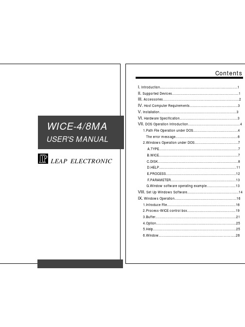
LEAP ELECTRONICContentsI. Introduction (1)II. Supported Devices (1)III. Accessories (2)IV. Host Computer Requirements (3)V. Installation (3)VI. Hardware Specification (3)VII. DOS Operation Introduction (4)1.Path File Operation under DOS (4)The error message (6)2.Windows Operation under DOS (7)A.TYPE (7)B.WICE (7)C.DISK (8)D.HELP (11)E.PROCESS (12)F.PARAMETER (13)G.Window software operating example (13)VIII. Set Up Windows Software (14)IX. Windows Operation (16)1.Introduce File (16)2.Process-WICE control box (19)3.Buffer (21)4.Option (25)5.Help (25)6.Window (26)WICE-4/8MA USER'S MANUALI. IntroductionWICE-4/8MA is a high performance in-circuit emulator for developing and debugging ROM/SRAM applications. It offers real-time emulation up to 8M bit.WICE-4/8MA interface to an IBM PC or clone via the printer port.It is able to be driven under DOS or Windows 3.1/95.It is mainly a manual for WICE-8MA, if you buy a WICE-4MA, the operation is the same as WICE-8MA.II. Supported DevicesWICE-4MACapacity Quantity Device Low voltage Device2K ¡Ñ 8 2 2716 -4K ¡Ñ 8 2 2732 -8K ¡Ñ 8 2 2764 -16K ¡Ñ 8 2 27128 -32K ¡Ñ 8 2 27256 -64K ¡Ñ 8 2 27512 -128K ¡Ñ 8 2 27010 27LV010256K ¡Ñ 8 2 27020 27LV020512K ¡Ñ 8 1 27040 27LV04064K ¡Ñ 16 1 271024 27LV1024128K ¡Ñ 16 1 272048 27LV2048256K ¡Ñ 16 1 274096 27LV40962K ¡Ñ 8 2 6116 -8K ¡Ñ 8 2 6264 -32K ¡Ñ 8 2 62256 -128K ¡Ñ 8 2 628128 --1-WICE-4/8MA USER'S MANUAL WICE-8MACapacity Quantity Device Low voltage Device2K ¡Ñ 8 2 2716 -4K ¡Ñ 8 2 2732 -8K ¡Ñ 8 2 2764 -16K ¡Ñ 8 2 27128 -32K ¡Ñ 8 2 27256 -64K ¡Ñ 8 2 27512 -128K ¡Ñ 8 2 27010 27LV010256K ¡Ñ 8 2 27020 27LV020512K ¡Ñ 8 2 27040 27LV0401024K¡Ñ 8 1 27080 27LV08064K ¡Ñ 16 1 271024 27LV1024128K ¡Ñ 16 1 272048 27LV2048256K ¡Ñ 16 1 274096 27LV40962K ¡Ñ 8 2 6116 -8K ¡Ñ 8 2 6264 -32K ¡Ñ 8 2 62256 -128K ¡Ñ 8 2 628128 -512K ¡Ñ 8 2 628512 -P.S.Low voltage type must have 3.3V adaptor and switch to 3.3 voltage selection.III. Accessories1. Standard Accessories:* WICE-4/8MA mainframe x 1* 26-pin cable x 1* 32-pin single connector flat cable x 1* 32-pin double connector flat cable x 1* 16 bit 40-pin module + flat cable x 1* 4 signal line hook x 1* 28-pin IC socket x 2* System software disk x 1* User manual x 1-2-WICE-4/8MA USER'S MANUAL* DC power adaptor x 1* 3.3V adaptor x 22. Option* 28F002 module driver* PLCC adaptorIV. Host Computer Requirements*IBM PC or compatible computer (above 386)*MS-DOS VER 3.0(or above); Windows 3.1/95V. Installation1. Plug one head of 26-pin cable in WICE-4/8MA, and another headin printer port.2. Switch the selector to choose which voltage device you want toemulate. For example, you want to emulate 5V device then switch the selector to 5V.3. Plug adaptor in 110V power socket and the other head in WICE-4/8MA DC IN.4. If you want to emulate 3.3V device, add 3.3V adaptor is needed.Then plug 32-pin cable in WICE-4/8MA.5. Install the system software. (key in INST8MD.EXE under DOS)6. Run the software.VI. Hardware Specification1. Transmit by printer port.2. One printer port can control 2 units of WICE-4/8MA.-3-WICE-4/8MA USER'S MANUAL3. The switch is able to be adjusted to 3.3V or 5V.(Note:There is no reverse protection when the switch is at 3.3V if without 3.3V adaptor.)4. Signal line is able to control RESET or HOLD o n targetboard.VII. DOS Operation IntroductionNote:Change W8 into W4 if you operate WICE-4MA.1. Path File Operation under DOSw8 [d:][path] file name [/type] [/#ID] [/EVEN] [/ODD] [/RESET] [/LPTn] [/Nn] [/Snnnnnn] [/V](1) [d:] [path] file name: the files which users need to be simulated,include set the disk number/path/file name/accessory filename.(2)[/type]: assign the name of device[/16] or [/2716] = 2K ¡Ñ 8bits[/32] or [/2732] = 4K ¡Ñ 8bits[/64] or [/2764] = 8K ¡Ñ 8bits[/128] or [/27128] = 16K ¡Ñ 8bits[/256] or [/27256] = 32K ¡Ñ 8bits[/512] or [/27512] = 64K ¡Ñ 8bits[/010] or [/27010] = 128K ¡Ñ 8bits[/020] or [/27020] = 256K ¡Ñ 8bits[/040] or [/27040] = 512K ¡Ñ 8bits[/080] or [/27080] = 1024K ¡Ñ 8bits(3) [/#ID]: assign the emulator. One printer port is able to controltwo units of WICE-4/8M and each WICE-4/8M has twoport.[/#1A]=WICE-#1A-4-WICE-4/8MA USER'S MANUAL[/#1B]=WICE-#1B[/#2A]=WICE-#2A[/#2B]=WICE-#1B(4) [/EVEN]: set the data of even position loaded(5) [/ODD]: set the data of odd position loaded(6) [/RESET]: set the reset signal after transmission, reset the circuit.(7) [/LPTn]: select the number of Printer Port, n might be 1-4. If you do not want to set this parameter, it will automatically set to "LTP1".(8) [/Snnnnnn]: select the beginning position of loaded files.(9) [/V]: verify the data which is from PC to WICE-4/8MA to make sure the correction of the data.(10) [W8/?]: mention that the way to set parameter. It will show you like following.Example:W8 TEST. BIN /010 /VEmulate 27010 from file TEST.BIN to port A-5-WICE-4/8MA USER'S MANUALThe error message1. Have not source file name enter!without assigning the source of the file name2. Source file not found!could not find the source file3. Source file read error!the error made from reading source file4. Source file not *.EXE file or bad!the source file is not *.EXE or the file length is not enough5. Illegal start offset address!the start address is wrong6. Start offset > file length!the start address is longer than the file length7. Illegal download source file allocate to device numberError in downloading source file allocate to device number8. Download data to WICE-8MA error!the error from transmitted verification9. Check the power and the cable of WICE!make sure the conncetion of power and the cable of WICE 10. Port B not ready check Port B please!please check Port B if it is ready11. WICE hardware do not define parallel port (LPTn)!WICE hardware do not define parallel port address-6-WICE-4/8MA USER'S MANUAL-7-2. Window Operation under DOSKey in WICE-4/8/MA under this path and get into main chart.TYPE : set the type of outputWICE : the function of output/inputDISK : disk loading operating systemHELP : operating introduction and EPROM pinout introductionPROCESS : process the data in bufferPARAMETER : set the parameterA. TYPE:Set the IC type and output position[T] Set emulator typeAccording to IC position for choosing the type of ICB. WICE:Transmit the data from buffer to WICE.1. [M] Move data block to WICEMove buffer data from 0000 position to WICE2. [Shift] [M] Move any block to WICE User can transmit anyblock data to WICEWICE-4/8MA USER'S MANUAL3. [R] Read WICE data into bufferRead the data from WICE into buffer4. [N] Read WICE data check sumCalculate and show the data check sum5. [V] Verify WICE/Buffer dataVerify the difference between WICE and buffer, if there are differences it will show you the address and the data. 6. [Ctrl] [C] Clear WICE data to "FF"h”hClear WICE data to "FF"h7. [E]Move data with error checkExamine error while transmitting data”h8. [1] Reset target board (Pluse)Send the pluse signal to target board, it is a signal which is from high to low and then back to high.9. [Shift] [1] Change RESET Output stateChange RESET output state from high to low or from low to high.10. [2] Change "HOLD" output stateChange HOLD output state from high to low or from low to high.11. [3] Change "USER" output stateChange USER output state from high to low or from low to high.12. [Z] Change memory (cache) segmentChange memory cache segmentC. DISKDisk loading operating system.1. [Ctrl] [D] List disk directoryList the file name/length/date in the disk-8-WICE-4/8MA USER'S MANUAL2. [L] Load disk data file to bufferDownload disk files to PC buffer, it will list 26 types of transmission format. Normally, it is [2] Binary/Machine Code or [3] Intel HEX format. You do not have to key in the file name, simply use A:\*.* to list the data in the file and download it by using the cursor.Start address [00000]: indicate the start address of buffer, Fill 0/FF/NO: fill in [ ].[0]: clear the buffer data to 00h before loading[F]: clear the buffer data to FFh before loading[N]: do nothing to buffer before loading3. [S] Save buffer data to diskSave buffer data to floppy or hard disk4. [Shift] [L] Load encryption data to bufferload encryption data to buffer5. [Shift] [S] Save encryption data to diskSave encryption data to disk6. [Ctrl] [M] Define macro keyUser define macro key to bufferMacro key capture:[ ] you can set from F1 to F10-9-WICE-4/8MA USER'S MANUAL-10-Macro key remark: [ ] key in the note of file name Example:Set the procedure in ROM.BIN into macro key.(1) Press [Ctrl] [M] and do the set-up like following: Macro key capture: [F2]Macro key remark: [ ROM.BIN](2) Press [Enter](3) Press [L] to load 26 types and click [2] Binary/ Machine Code(4) Press [Enter] to load A: *.* then [Enter], after listing file name move the cursor to ROM.BIN(5) Press [Enter], choose the start address 0000. Press [F] to select blank and fill the data. Then press [Enter] to start loading.(6) Press [Ctrl] [M] to end the set-up procedresNote: You can press [F2] to repeat above procedures.7. [Ctrl] [E] Erase macro keyErase the set-up macro key8. [Ctrl] [T] List macro keyList macro key and its explanatory notes9. [Ctrl] [L] Load macro key fileLoad macro key file to buffer, it will automatically load UNIV.KEY when you get into the system.10. [Ctrl] [S] Save macro key file to diskSave macro key file to disk11. [Shift] [T] View text fileView text file on screen, the function is the same as "type" in DOS.WICE-4/8MA USER'S MANUAL12. [Ctrl] [I] Rest time, system lockRest time which you can set password to avoid someone else usurp the data.13. [0] To decompose big file (>262K)Decompose big file into small one. Please refer to HELP.14. [W] Select mega buffer fileSelect mega buffer in disk15. [Shift] [I] Initial mega file buffer file in diskProduct 1MEGA buffer in disk16. [Ctrl] [Q] Exit, Return DOSEnd of work, press [S] SAVE all parameter and file then exit Press [Y] EXIT return to DOS, not saving the dataPress [N] No not leaving the emulator softwareD. HELPOperating introduction and pin configuration1. [H] HELPOperating introduction, you can check by [Pgup] [Pgdn] 2. [ I ] Device informationProvide IC pin configuration-11-WICE-4/8MA USER'S MANUALE. PROCESSProcess the data in buffer.1. [D] Dump/Edit buffer dataShowing the whole buffer data which contain HEX/ASCII to edit. It will show you the binary, hexadecimal and ASCII CODE of code format.Key in [Ctrl] [E] to edit HEX[Ctrl] [A] to edit ASCII[Ctrl] [D] to go the data you want to examine[ESC] back to main screenThis function will provide you a easy way to DUMP and EDIT. You can press [Ctrl] [F2] into a special process buffer 2. [U] Display buffer used mapShow the current buffer condition to provide users analyzing 3. [Shift] [D] Edit encryption tableProvide a spare buffer (256K byte) to process input password, like encryption code4. [Shift] [C] Buffer data lock/unlockProtect the data in main buffer. You may retrieve thedata by processing the same password.5. [Ctrl] [N] Read memory check sumRead memory check sum from buffer6. [Ctrl] [F] Buffer fill (FFh) dataFill buffer with FFh data7. Buffer fill (00h) dataFill buffer with 00h data8. Fill sequential word into allFill buffer with sequential word9. Fill sequential byte into all-12-WICE-4/8MA USER'S MANUALFill buffer with sequential byte10. [Ctrl] [X] Divide 16/32/64 to 8 bitDivide buffer data into 8 bit11. [Shift] [X] Combine 8 to 16/32 bitCombine 8 bit into 16/32 bitF. PARAMETERSet the parameter.1. [Shift] [A] 8 bit BUS all addressTransmit 8 bit data from buffer to WICE-4/8MA2. [Shift] [E] 16 bit BUS Even addressTransmit 16 bit ,Even data from buffer to WICE-4/8MA 3. [Shift] [0] 16 bit BUS Odd addressTransmit 16 bit ,Odd data from buffer to WICE-4/8MA 4. [Ctrl] [0] Select printer portSelect printer portG. Window software operating exampleTransmit BIN of 27010 to drive# on WICE-4/8MA.1. Press [TYPE] and select [0] WICE#A (27010) to set the size of WICE#A-13-WICE-4/8MA USER'S MANUAL2. Select [L] Load disk data file to buffer in DISK, it will showyou 26 transmission types . Choose Binary/Machine code,then [Enter], the start address is (00000), [Enter],Fill 0/FF/No: [N], then the data is loading in buffer.3. Select WICE key in [E], it will show you [WICE-1#A (27010)-378 address is A], then press[Enter] for transmitting the datato drive#A.4. Turn on target boardVIII. Set Up Windows Software1. Standard Requirements*IBM PC or compatible computer (above 386)*10M hardisk space*WINDOWS 3.1/95*8M RAM2. Installation Procedures[A] Please back up your software disk.[B] Turn on your computer and set the Windows in, please in the-14-WICE-4/8MA USER'S MANUAL"SETUP DISK" and execute the "SETUP.EXE" in order to set the WICE-4/8MA main program into computer.[C] Your screen will show the dialogue to choose the set-up path, please key in the path of the file that you want to install.[D] When you finish the set-up, it appears a new program in your Windows explorer.[E] You can check WICE-4/8MA chart twice to execute the main program.3.Connect WICE-4/8MAIntroduction:Please follow the procedures to connect the WICE-4/8MA with PC.-15-WICE-4/8MA USER'S MANUAL-16-Connection Procedure:[A] Plug one head of cable in WICE-4/8MA and the other head in printer port.[B] Turn it on and execute the WICE-4/8MA main program.[C] Select Process-WICE control box on the MENU and turn into WICE Control Box.(Or click the third button on Tool bar).[D] Take a look at WICE DRIVE SELECT, if it is dissolved then it doesn't connected. You can click Auto Detect WICE in WICE Control Box, do the detection again.[E] Click Auto Detect WICE, if it is still dissolved then check [A] [B] and repeat [C] [D] [E].IX . Windows OperationWICE-4/8MA MENUMenu IntroductionFile : functions of file processBuffer : function of file editingProcess: hardware processOption : working environment optionHelp : on line helpWindow : re-arrange windows1. Introduce FileWICE-4/8MA USER'S MANUAL-17-Load: load in a old fileIt will show you a Dialog box like followingPath : to select load pathName : to select load nameFile format : to select file format Buffersize : to select buffer range (max 16Mbyte)Source : to select the start file address and end address (Program will self-judge if the input correct or not)Destination : to select the buffer destination start address for disk and input unused block.unused fill : unused data fill.Browse : to select file by browseWICE-4/8MA USER'S MANUAL-18-Save: save filesIt will show you a Dialogue box like following.Path : to select save pathName : to select save nameFile format : to select file formatSelect buffer range : to select buffer range (Program will self- judge if the input correct or not)Destination : to select the buffer destination start address for disk and input unused block.unused fill : unused data fill.Browse : to select file by browseBuffer range : to fill the buffer range in the destination File range : to use file range to fill select buffer range Close: close the current window (current window is focus window)Exit:exit current programWICE-4/8MA USER'S MANUAL-19-2. Process-WICE control boxIntroductionMainly to open the "WICE control box" dialog and control the hardware of WICE-4/8MA. Explain the approach like following about "WICE control box"”.[WICE control box]WICE DRIVE SELECTTo select the device number of emulation device.SOURCESelect the data which will transmit to WICE-4/8MA PROGRESSShow the progress at the presentWICE-4/8MA USER'S MANUALStart addressSelect the start address of transmissionTransfer with verifyVerify data while transmitting, but it delay the transmitting timeMove data block to WICETransmit data to WICE-4/8MARead WICE data into bufferRead data from WICE-4/8MARead WICE data check sumRead data check sum from WICE-4/8MAVerify WICE/Buffer dataVerify the data in buffer and WICE-4/8MACheck sumShow the check sum of dataUSERHi: turn the USER test hook to high level voltageLow: turn the USER test hook to low level voltageHOLDHi: turn the HOLD test hook to high level voltageLow: turn the HOLD test hook to low level voltage-20-WICE-4/8MA USER'S MANUAL-21-RESETPluse: In RESET test hook, it will output pluse from Low to High Hi: turn the RESET test hook to high level voltageLow: turn the RESET test hook to low level voltageAuto Detect WICEDetect the connection of WICE-4/8MANote:It will delay transmitting time while you choose "Transfer with verify".3. BufferNew:open a new edit window to use a blank bufferWICE-4/8MA USER'S MANUAL-22-Jump: move the cursor to an address where you would like to go. Just fill the address and press OK, then you can go there quickly.Block: for copy, or move, or exchange the block content.Action: to select to block1. copy : to copy block2. move: to move block3. swap: to swap two blocksSource: to select source block.DESTINATION: to select the destination address.Buffer range: to fill the buffer range in the destinationFile range: to fill the file range in the destinationNote: If input wrong to the above selection, the program willsend message to remind you.WICE-4/8MA USER'S MANUAL-23-Search: search for the goal dataStyle: select the search style( use Binary or ASCII to search)Action : to select the search startSearch next : to search the next oneFirst : the first search dataTarget : the target data (ASCII or Binary)Range:Start Address:search start addressEnd Address :search end addressMax range :the maximum buffer addressFile range :the maximum range of file address that you have already load.Fill:fill in dataWICE-4/8MA USER'S MANUAL-24-Fill data : select fill data:All fill bit 1 :All bit fill "1"All fill bit 0 :All bit fill "0"User define : to fill the user define byte.Range : to select and fill the rangeMax range : to fill the range with maximum butter range File range : to fill the range with the maxumum file range Get Check Sum: get the check sum from the Edit.Range: to select the range of calculationMax range: the maximum buffer rangeFile range: the maximum file rangeInsert File: Insert the file to the edit file. (only accept Binary type)Use Map: use map to reflect the data of the edit file.The window of use mapWICE-4/8MA USER'S MANUAL-25-Buffer resize: resize the bufferSize: select the length of buffer4. OptionIntroductionThese selections are for you to set the working environment.Hide status bar: you can hide status bar by choosing this Text color: you have 15 colors option to chooseBig tools bar & Small tools bar: you can shift big tools bar or small tools bar5. HelpMain guide: You can choose this function if you have any questionabout WICE-4/8MA.WICE-4/8MA USER'S MANUAL-26-Device information: Show the information of emulated devices pinout like following.6. WindowCascade: to use cascade way for arranging windowsTile[horizontal]: to use horizontal way for arranging windowsWICE-4/8MA USER'S MANUAL-27-Tile [vertical]: to use horizontal way for arranging windows[ arrange windows by horizontal way ]Arrange Icons: to use arrange icons for arranging windows[ icons arrangement]Close All: to close all of windowsWICE-4/8MA USER'S MANUAL-28-7. Tools BarFile---Load function File---Save functionWICE Control box。
讯维高清四画面分割器

讯维高清四画面分割器型号:XW-ZXV0401使用手册产品介绍:四画面分割器是我公司研发并生产的高清分割器,是专用的视频处理与控制设备,主要功能是在高分辨率的显示设备(平板/投影机)上以全屏或多窗口模式同时显示四路视频信息;也就是将多路HDMI、VGA、CVBS等视频画面,选择其中的4通道画面在显示器件上分割显示。
支持多种分辨率输入,支持4路USB 同步控制。
输出支持HDMI与VGA同步显示。
性能特点:四通道信号可分割显示到HDMI或VGA显示,每个通道支持3种信号输入,支持4路USB同步控制。
产品应用:1.公共视讯系统(证券公司,期货市场,金融证券等)2.电脑教学系统。
3.高品质多媒体展示。
4.视讯会议。
5.计算机,液晶和等离子高清显示会场。
产品图片1U机箱前后面板2U机箱前后面板操作方法:一、按键遥控操作:按menu键循环设置:MODE(模式),FULL SCREEN(全屏显示),保存预案(Save mode),调用预案Load mode,设置输入源信号In channel(选择通道按OK进入通道信号选择1、HDMI,2、CVBS,3、VGA),USB切换。
遥控器快捷键:AV=MODE,VGA=全屏显示,A=调用预案,V=USB 切换。
1、模式设置包含4种模式:1画面模式,2画面等分模式,3画面等分模式,4画面等分模式。
2、全屏显示:选择某一路信号源作为全屏显示。
3、保存预案:支持用户自定义16种预案。
4、调用预案:调用保存好的预案。
5、设置输入信号源:每一路输入信号源都可以独立设置,例如将第一路信号源设置为HDMI。
6、USB切换:4画面分割器具有4个USB接口,但在某一时刻只能使用一个USB接口。
换言之,用户可以切换至任意一个USB接口进行使用。
面板包含按键输入,红外遥控器输入,LCD液晶显示屏显示输出信息。
按键功能和红外遥控器功能一致。
LCD负责显示输出信息。
按键包含了数字键0~9,MENU键,OK键,ESC键,CTRL键。
SIR4中文说明书中文图最终版 (1)

高频电源安装操作运行维护手册
目录
1. 概述 .................................................................................................................................................................. 9 1.1. 型 号 .................................................................................................................................................... 10 1.2. SIR: 静 电 除 尘 器 控 制 装 置 系 列 的 一 员 ....................................................................................... 10
4. 电气数据 ........................................................................................................................................................ 26 4.1. 概 述 .................................................................................................................................................... 26 4.2. 电 源 电 流 ........................................................................................................................................... 27 4.3. 要 求 的 电 缆 ....................................................................................................................................... 27
Roadmaster 4-wire Wiring Harness 安装指南说明书

Parts(1) 4-wire wiring harness, 27 feet in length (4) Hy-Power ™ diodes(1) 10-12 gauge butt connector (yellow) (1) 6-14 ring terminal(1) 3-foot length of split loom (11) wire tiesNote: although this kit works in the vast majority of ve-hicles, there are a few in which it does not. Before begin-ning, make certain this kit can be installed — check under ‘Vehicle-Specific Info' at .Read the instructions before installing the kit components. Failure to understand how to install this product could result in property damage, personal injury or even death.CAUTIONDo not install this kit in a 1999-2003 Ford Windstar, 2004 and newer Ford Freestar, or in any vehicle using a “low side switching” system. A low side switching sys-tem will prevent the taillights from functioning properly when they receive power from the motorhome.Use either magnetic tow lights or a taillight bulb and socket kit to wire these vehicles for towing.Step AIdentify the vehicles' lighting systems;determine if additional components are required 1. The vehicle will be wired for towing according to the type of brake and turn signals in both vehicles. There are two types — combined or separate. In a combined system1IMPORTANT NOTICE!Safety DefinitionsStatements in these instructions identified as follows are of special significance. WARNING indicates a potentially hazardous situ-ation which, if not avoided, could result in property damage, serious personal injury or even death. CAUTION indicates a potentially hazardous situa-tion which, if not avoided, may result in property dam-age, or minor or moderate personal injury.CAUTION used without the safety alert symbol in-dicates a potentially hazardous situation which, if not avoided, may result in property damage.NOTERefers to important information and is placed in italic type. It is recommended that you take special notice of these items.(Figure 1), the brake light does the flashing for the turn signal; in a separate system (Figure 1), there are amber or red turn signal lights which are separate from the brake lights. Note: if the motorhome has a separate system, use a test light to see if a 3-to-2 converter has been installed — if the same circuit energizes both the turn signals and the brake lights, a converter has been installed.The 3-to-2 converter will, in effect, change the brake and turn signals from separate to combined.2. Determine if additional components are required — This kit contains all the components for most towed vehicle-motorhome combinations. However…• …if the motorhome has a separate lighting system and the towed vehicle has a combined lighting system, a Brite-Lite ™ 3-to-2 wiring converter (ROADMASTER part number 732, see page four) is required.• …if both the motorhome and the towed vehicle have separate lighting systems, there are two options:First option — install a Brite-Lite 3-to-2 wiring convertercontinued on next pageFigure 1Economy wiring kitpart number 152Installation InstructionsAll specifications are subject to change without notice.Towing and Suspension Solutions 855073-00 05-13be necessary to remove the taillight assemblies from the exterior of the vehicle to gain access to the wiring.)2. With a circuit tester, identify the brake light, taillight and turn signal wiring.3. Wire the diodes according to the appropriate schematic (on page three) that matches your combination of vehicles.4. Use the brown wire you saved in step C4 to jump the diodes attached to the taillights, as shown in the schemat-ics. Note: use the yellow female spade connector on the diode you will use to jump the brown wire.5. Use the included ring terminal and a self-tapping screw (not included) to attach the ground wire.Note: to avoid grounding problems, attach the wire to a good chassis ground, preferably directly to the frame.CAUTIONRefer to the owner’s manual before attaching the ground wire. Some manufacturers stipulate that ground wires must be attached at specific locations.Significant damage to the vehicle’s electrical system, as well as other consequential, non-warranty damage will occur if the ground wire is not attached at one of these points.6. If it was necessary to drill a hole, seal it with silicone sealant after you have routed the wires through.Attach the diodes as close to the towed vehicle’s lights as possible, to avoid interaction with other cir-cuits which may be tied into the center brake light, the running lights, the turn signals or the brake light wires. Attaching the diodes farther away may cause the towed vehicle’s lights to work improperly, as well as cause damage to other electrical components in the vehicle. Failure to follow these instructions may result in property damage, personal injury or even death.CAUTIONFailure to attach the diodes as indicated in the wiring diagrams will create a backfeed through the vehicle’s electrical system, which will allow electrical current from the towed vehicle to disrupt one or both of the vehicles’ electrical systems.Additionally, if a supplemental braking system is installed it may not operate, or may only operate inter-mittently.Wire the towed vehicle according to the instructions above, and the appropriate schematic. Improperly wiring the towed vehicle may cause an electrical malfunction or other damage, which may result in property damage, personal injury or even death.7. Test each of the circuits to confirm that the lighting func-tions correctly.2continued from preceding page(part number 732) on the motorhome. Use the schematic labeled “Combined towed vehicle to separate motorhome” (on page three) to wire the vehicle.Second option — In order to maintain separate brake and turn signals, the power cord must have at least five circuits. There are a number of power cords available for this purpose, such as 7-to-6-wire Flexo Coil, part number 146-7 (see page four).Two additional diodes (part number 792, see page four) and one 10 ga. x .250 female spade connector are also required for this option.Step BAttach the wiring harness1. Attach one end of the wiring harness to the electrical socket at the front of the towed vehicle. Connect the wires according to the instructions that came with the electrical socket.Step CRoute the wiring harness1. The wiring harness will be routed to the rear of the vehicle, then split and attached to the back of both taillight assemblies. Before you begin, plan a route that avoids the possibility of fraying or melting the wiring against moving parts, sharp edges, the fuel lines or hot components. If the OEM wiring harness is accessible, plan a route alongside it.2. Route the wiring harness. Where appropriate, use a section of the included split loom to protect the wires; use one or more of the included wire ties to secure the wiring in place.Route the wiring harness to avoid moving parts, sharp edges, the fuel lines or hot components such as the engine or exhaust system.Wiring exposed by moving parts, sharp edges or hot components may cause a short circuit, which can result in damage to the vehicle’s electrical system as well as other, consequential damage.Wiring which is attached in close proximity to the fuel lines may ignite the fuel.Failure to follow these instructions may cause prop-erty damage, personal injury or even death.3. At the rear of the vehicle, find a suitable point to gain access to the vehicle’s taillights.4. Route the wiring harness to the closest taillight assembly and then over to the other taillight assembly.Trim the excess wiring. (Save the brown wire; you may use it in step D4.) Then separate the bonded wires in the harness and, depending on the lighting systems in both vehicles (see page three), peel back the appropriate wire(s) to the other side.Step DWire the vehicle for towing1.Expose the wires in both taillight assemblies. (It may3CAUTIONThe color codes listed below are the most commonly used. However, color coding is not standard with all manu-facturers.Use the color codes for initial reference only; confirm the function of each wire with a circuit tester.The towed vehicle's lighting system may not function, or function improperly, if the wires are not connectedcorrectly. Cross-wiring may also cause a short circuit, a blown fuse or other non-warranty damage.Wiring schematics4Hy-Power ™ diodesIf your combination of vehicles requires additional diodes, use Hy-Power diodes. They have a heavy-duty, powder-coated aluminum heat sink, and each diode is protected against the elements — all components are housed in-side an epoxy-sealed, powder-coated aluminum case. Includes detailed wiring instructions.790 one Hy-Power diode 792 two Hy-Power diodes 793 three Hy-Power diodes 794 four Hy-Power diodesBrite-Lite ™ 3-to-2 converterIf you have this — the motorhome has separate brake and turn signal lights; the towed ve-hicle has combined brake and turn signal lights.Then you need this — the Brite-Lite converter connects a vehicle with a separate brake and turn signal system to one with a combined brakeand turn system, while delivering more current to the towed vehicle’s brake and turn signals for brighter illumination.732Brite-Lite 3-to-2 wiring converterFlexo-Coil ™ power cordsThe wires in Flexo-Coil cords are water-, oil- and chemical-resistant, and the plugs are injected with silicone to prevent corrosion. They ex-pand to more than eight feet and conveniently contract for storage. Part number 146-7 — 7- to 6-wire cord with plugs, sockets and socket bracket Part number 164-7 — 7- to 4-wire cord with plugs, sockets and socket bracketStop pulling fuses to tow!How about if you never had to spend another minute with your face on the floor mat, gazing up into a black void, hunting for a miniscule piece of plastic playing hide and seek? You don’t have to.FuseMaster eliminates the necessity of having to remove a fuse for towing, then having to reinsert it for driving. After it’s installed you simply flip a switch to accomplish the same task.There are several FuseMasters which, collectively, fit most vehicles which must have fuses removed for towing. For the fit list, click the ‘Vehicle Specific Info’ tab at .Don't do the Fuse Limbo…76510 fits the majority of vehicles where a fuse must be pulled 76511 a longer version of the 7651076512 where two fuses are required to be removed 76513 use to replace a heavy-duty, 50-amp fuse76514 for the 2013 Chevrolet Traverse, Buick Enclave and GMC Acadia…Just flip a switch!Advertisement。
WiRE 4操作说明 中文

WiRE4
INDEX
TM001-System Start-up……………….………………………….……………..……………………………….1 TM002-Sample Viewing and Configuration Change………………………………………………….3 TM003-Measurement Set-up and Data Acquisition………………………………………………….9 TM004-Depth Profiling……………………………………………………………………………………………16 TM005-White Light Image Capture, Montaging and Surface generation ……………… 19 TM006-Point Imaging……………………………………………………………………………………………..31 TM007-Data Processing and Simple Analysis…………………………………………………………..34 TM008-Multi-file processing……………………………………………………………………………………47 TM009-Multi-file Data Analysis (Univariate)……………………………………………………..…….58 TM010-Database Searching and Creation……………………………………………………….…….61
配置更改(测量过程中)
配置也可以在编辑当前测量时改变。当用户需要利用不同激发波长分析同一样品同一区域时,是 很有用的。
利用测量设置按钮
,在 Acquisition 选项中编辑激光和光栅(更换激光后,激光功率、曝光
WireBond操作说明中文版

WireBond操作说明中⽂版File (main menu)管理bonder的操作系統和打線程式的指令。
New…建⽴新的打線程式,所有的參數均為預設值。
在建⽴新的程式前需將原先的程式儲存起來否則所作的程式將會遺失。
在開新的程式後會有⼀對話⽅塊來作確認。
按"Enter" (Okay): 建⽴新的打線程式。
(或按"Escape" (Cancel):取消此程序。
)複製打線的參數假如要將Mode 11內所有的參數複製到新的打線程式,可依下列的步驟完成。
在Mode 1的module number鍵⼊"1"後按"Enter"。
Chip number鍵⼊"0"後按"Enter"。
按"Escape" (Cancel):離開Mode 1。
此時Mode 1的Chip 0所有的參數均與Mode 11相同。
Load…載⼊存在的打線程式。
在載⼊程式前需將原先的程式儲存起來否則所作的程式將會遺失。
在載⼊程式後會有⼀對話⽅塊來作確認。
按"Enter" (Okay): 載⼊存在的打線程式。
(或按"Escape" (Cancel):取消此程序。
)Load bond program使⽤游標選擇要載⼊的程式。
按"Enter" (Okay): 載⼊所選擇的打線程式。
按"Escape" (Cancel):離開此表單。
Save as…儲存現在所使⽤的打線程式。
使⽤鍵盤輸⼊適合的程式名稱。
可輸⼊254個字,不可使⽤特殊字元。
若有相同的名稱,將發出⼀個對話⽅塊訊息來確認按"Enter" (Okay): 儲存檔案。
(或按"Escape" (Cancel):取消此程序。
) 按"Escape" (Cancel):離開此表單。
- 1、下载文档前请自行甄别文档内容的完整性,平台不提供额外的编辑、内容补充、找答案等附加服务。
- 2、"仅部分预览"的文档,不可在线预览部分如存在完整性等问题,可反馈申请退款(可完整预览的文档不适用该条件!)。
- 3、如文档侵犯您的权益,请联系客服反馈,我们会尽快为您处理(人工客服工作时间:9:00-18:30)。
Sample Review 显示当前的仪器配置(激光/光栅),也可以改变配置。
Figure 6 inVia Reflex 样品观察条
更改配置
配置的改变需要用户了解使用的激光器、光栅和探测器。有些配置是不合适的,当用户使用时, 会出现一个对话框提醒用户这种配置没被校准。(因此是不能用的)
6
激光器改变时,根据系统的类型会发生下面的一条或者几条: Beamsteer 自动变化(仅当相应 beamsteer 已被设置时) Rayleigh 滤波片自动变化(仅当 Rayleigh 滤波片已被设置时) 扩束器自动变化(所有,紫外激光光路中有时没有扩束) 激光开关自动变化(所有) 内部校准硅片自动聚焦(仅 Reflex 型号) Renishaw inVia 光谱仪具有很高的灵活性,可升级,因此从前面配置中可得到所需要的自动化程 度。手动,半自动,全自动,全自动有效选择都是可以的。对于没有自动 rayleigh 滤波片的 inVia 仪器,用户必须打开仪器主机门(参考仪器主机门的开启和激光联锁的安全操作说明),手动更 换新波长的 rayleigh 滤波片。一些仪器具有自动转化模块,但是所有位置都被占据,在更换新滤 波片时也需要手动更换。 光栅更换时,相关的软件部分发生变化,但是机械部分没有发生变化。光栅会影响光谱范围和光 谱分辨率。对于所有 inVia 拉曼光谱仪,光栅更换的步骤是相同的。对于配有两块以上光栅的仪 器,用户必须手动更换光栅完成想要的配置。光栅背靠背安装,分开时需小心谨慎。任一光栅只 能被安装在两个位置中的一个上(仪器设计时确定)。手动安装/更换光栅:取下光谱仪外壳,插 上光栅保护罩,取下光栅,分开,安装新的光栅,取下光栅保护罩,重新盖好锁住主机外壳。
配置更改(测量过程中)
配置也可以在编辑当前测量时改变。当用户需要利用不同激发波长分析同一样品同一区域时,是 很有用的。
利用测量设置按钮
,在 Acquisition 选项中编辑激光和光栅(更换激光后,激光功率、曝光
时间和次数需要重新设置)。如果透镜组不匹配,运行编辑好的测量时会提示用户更换透镜。
8
TM003-Measurement Set-up and Data Acquisition
前提:使用者有一定的 WiRE 4 使用经验。
观察样品
inVia 和 inVia Reflex 拉曼光谱仪均可以通过目镜或者摄像头直接观察样品。 观察样品的模式可以通过 WiRE 软件中样品观察工具栏控制。 样品观察工具栏可以从 View 菜单中打开也可以直接点击 inVia 的样品观察工具栏 Sample Review 包括以下内容:
Figure 4 最新的 Renishaw 摄像头 5
Figure 5 摄像头设置
选择 auto exposure 会根据成像对比度和亮度调节曝光,但不一定适用于所有样品,因为这时视场 光阑是关闭状态,自动模式不断搜索(不能产生一个稳定的曝光值)。这种情况下,将自动曝光 关掉。 摄像头窗口可以改变大小来平衡成像的分辨率和成像大小。点击 Video capture pin、选择显示分 辨率。确保摄像头的纵横比保持不变,因为会影响摄像头校准。
InVia 拉曼光谱仪操作说明
WiRE4
INDEX
TM001-System Start-up……………….………………………….……………..……………………………….1 TM002-Sample Viewing and Configuration Change………………………………………………….3 TM003-Measurement Set-up and Data Acquisition………………………………………………….9 TM004-Depth Profiling……………………………………………………………………………………………16 TM005-White Light Image Capture, Montaging and Surface generation ……………… 19 TM006-Point Imaging……………………………………………………………………………………………..31 TM007-Data Processing and Simple Analysis…………………………………………………………..34 TM008-Multi-file processing……………………………………………………………………………………47 TM009-Multi-file Data Analysis (Univariate)……………………………………………………..…….58 TM010-Database Searching and Creation……………………………………………………….…….61
Figure 2 菜单中开始测量
可用的测量的不同模式
光谱采集(标准光谱采集) 直接成像采集 深度序列采集(样品不同深度采集光谱,仅 Z 方向) 扫描成像/StreamLineHR 扫描(水平面内光谱采集) StreamLine 扫描(水平面内高速光谱采集) StreamLineHR 3D 扫描
TM001-System Start-up
此模块详细介绍的拉曼光谱的操作步骤,从激光器、电脑软件的开启到整个系统运行后能够进行 拉曼光谱、光致发光及成像信息。 前提:与 inVia 拉曼光谱仪使用相关的所有电子组件最初为关闭状态,使用者有一定的 WiRE 4 使 用经验。
系统开启
1. 开机:打开仪器总开关,总开关在仪器的右手边。(CCD 制冷到正常工作温度需要 20 分钟) 2. 开电脑,开软件。 3. 软件开启后,系统所有相关马达开始位置检测。 4. 开激光器:打开需要使用的激光器,确保所有的钥匙或者开关的正确使用。(激光器的使用
注:标准应用条件下,打开仪器主机门将触动所有的激光联锁,除非激光开关关闭。如果联锁被 锁,关闭并重新锁住主机门,重新应用激光联锁。(Tools….Interlock…..Reset)
7
5. 换‘Grating’。(注:这不会引起透镜组变化,除非多个光栅已经匹配到同一激光器)
当然,如果配置与测量时需要使用的配置是一致的,没必要改变,上面一步可以跳过。
参照激光器使用说明书)
选择“Reference un-referenced motors only”,确定“OK”。 5. WiRE 3 软件完全打开后,激光器的 interlock 锁才能正常使用。
1
部分系统开始运行
很多情况下,准备使用仪器时,发现系统的一部分已经开启,这时开机步骤相应发生一定变化。 下面是几个例子,同时给出完全开机的正确步骤。 例1 inVia 光谱仪、电脑、软件全开着,所有激光器均关闭。 1. 清除 Wire 软件中所有的数据和窗口(保证所有的数据都保存)。 2. 打开需要使用的激光器。 3. 待激光器输出稳定后开始使用。
2. Configuration:使用者可以根据需要选择合适的激光器和光栅。不同的激光器具有不同的能量, 可能引起不等量的荧光干扰。
3. Confocality:给出用户标准共焦和高共焦两种选择。共焦程度决定了信号收集的区域大小。高 共焦收集信号的区域小,可以提高空间分辨率,比如做深度扫描,但会损失信号强度。
更改配置工具栏
1. 确保所有的文件和窗口关闭(检查是否有文件未保存) 2. 决定需要的配置 3. 换‘Laser’.(注:改变激光不仅改变激光器波长,对于相同的波长还要改变滤波片类型和光斑
的形状)。
4. 改变激光器时将会出现一个对话框提示用户改变相应的光谱仪透镜(如果需要改变)。如果这 个对话框出现,打开仪器(仪器激光开关会自动关闭),仔细更换透镜组。确保透镜更换到正 确的位置。关闭仪器主机门,锁好。
此模块详细介绍了采用 WiRE 4 如何设置不同的测量参数进行光谱测量。
确定测量类型
Measurement 是用来确定数据采集模式的。根据仪器的具体配置可以选择几种不同的模式。新的 测量可以通过菜单中的 Measurement……New……打开,也可以通过工具栏打开。
Figure 1 工具栏中开始测量
选择合适的测量模式后,出现测量设置对话框。此对话框包括所有的标准设置的选项,如 Range, Acquisition, File 和 பைடு நூலகம்dvanced。
Range 范围 Range 选项包括基本的设置,包括激光、所用光栅和所用扫描模式。
9
Figure 3 Range 选项
1. Grating scan type 有两种扫描类型 Static 一次取谱可以覆盖 400 cm-1 到 1000 cm-1,取决于使用的激发波长和光栅,只需 输入需要的中心波长。一次静态取谱比扫描取谱快,但一次取谱覆盖的光谱范围有限。 Extended 扫描取谱可以扫描输入的最高与最低波数之间的光谱范围,当静态取谱不能 覆盖需要的波数范围时使用。
要自检)。 3. 待激光器预热稳定后才能开始实验。
系统所有部件打开后,等待系统稳定,即可进行光谱测量。
2
TM002-Sample Viewing and Configuration Change
此模块详细介绍如下操作: 1. 利用雷尼绍摄像头观察不同类型的样品 2. 选择不同的激光器/光栅/CCD 摄像头配置
4
Figure 3 摄像头特性
在 video viewer properties 窗口,可以应用 use averaging。对于暗的对比度低的样品可以降低噪音, 但是会影响摄像头响应。 Capture filter properties 包括不同的摄像头设置。对于最近的摄像头(Figure 4),将增益设置到 high, 根据需要调节曝光。
激光开关控制 物镜选择(需手动转动物镜实物) 观察过程中的激光功率控制 观察过程中的扩束控制 选择激光器 选择光栅 inVia 型号的仪器,激光偏振的控制、CCD 探测器的选择也是可见的。