华为verilog教程
verilog 实验实验一具体步骤
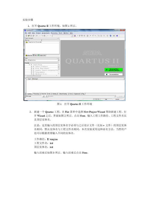
实验步骤1.打开Quartus II工作环境,如图1所示。
图1 打开Quartus II工作环境2.新建一个Quartus工程,在File菜单中选择New Project Wizard帮助新建工程。
打开Wizard之后,界面如图2所示。
点击Next,输入工程工作路径、工程文件名以及顶层实体名。
注意:这里输入的顶层实体名字必须与之后设计文件(比如.v文件)的顶层实体名相同,默认实体名与工程文件名相同,本次实验采用这种命名方法,当然用户也可以根据需要输入不同的实体名。
工作路径:E:\xinjian工程文件名:led顶层实体名:led输入结束后如图3所示。
输入结束后点击Next。
图2 New Project Wizard界面图3 输入设计工程信息3.添加设计文件,界面如图4所示。
如果用户之前已经有设计文件(比如.v文件),那么再次添加相应文件,如果没有完成的设计文件,点击Next,之后添加并且编辑设计文件。
图4 添加设计文件4.选择设计所用器件。
由于本次实验使用Altera公司提供的DE2开发板,用户必须选择与DE2开发板相对应的FPGA器件型号。
在Family菜单中选择CycloneII在Target device选项框中选择Specific device selected in ‘A vailable devices’ list 在A vailable device列表中选择EP2C35F672C6这个型号的器件。
完成后如图5所示,点击Next。
图5 选择相应器件5.设置EDA工具。
设计中可能会用到的EDA工具有综合工具、仿真工具以及时序分析工具。
在本次实验中不使用这些工具,因此点击Next直接跳过设置。
图6 设置EDA工具6.查看新建工程总结。
在基本设计完成后,Quartus II会自动生成一个总结让用户核对之前的设计(如图7所示),确认后点击Finish完成新建。
图7 新建工程总结在完成新建后,Quartus II界面中Project Navigator的Hierarchy标签栏中会出现用户正在设计的工程名以及所选用的器件型号,如图8所示。
中文版VerilogHDL简明教程
Verilog HDL是一种硬件描述语言,用于从算法级、门级到开关级的多种抽象设计层次的数字系统建模。
被建模的数字系统对象的复杂性可以介于简单的门和完整的电子数字系统之间。
数字系统能够按层次描述,并可在相同描述中显式地进行时序建模。
Verilog HDL 语言具有下述描述能力:设计的行为特性、设计的数据流特性、设计的结构组成以及包含响应监控和设计验证方面的时延和波形产生机制。
所有这些都使用同一种建模语言。
此外,Verilog HDL 语言提供了编程语言接口,通过该接口可以在模拟、验证期间从设计外部访问设计,包括模拟的具体控制和运行。
Verilog HDL语言不仅定义了语法,而且对每个语法结构都定义了清晰的模拟、仿真语义。
因此,用这种语言编写的模型能够使用Verilog仿真器进行验证。
语言从C编程语言中继承了多种操作符和结构。
Verilog HDL提供了扩展的建模能力,其中许多扩展最初很难理解。
但是,Verilog HDL语言的核心子集非常易于学习和使用,这对大多数建模应用来说已经足够。
当然,完整的硬件描述语言足以对从最复杂的芯片到完整的电子系统进行描述。
历史Verilog HDL语言最初是于1983年由Gateway Design Automation公司为其模拟器产品开发的硬件建模语言。
那时它只是一种专用语言。
由于他们的模拟、仿真器产品的广泛使用,Verilog HDL 作为一种便于使用且实用的语言逐渐为众多设计者所接受。
在一次努力增加语言普及性的活动中,Verilog HDL语言于1990年被推向公众领域。
Open Verilog International (OVI)是促进Verilog发展的国际性组织。
1992年,OVI决定致力于推广Verilog OVI标准成为IEEE标准。
这一努力最后获得成功,Verilog 语言于1995年成为IEEE标准,称为IEEE Std 1364-1995。
Verilog中的一些语法和技巧

Verilog中的⼀些语法和技巧1、.2、.3、Reg型的数据类型默认初始值为X。
reg型数据可以赋正值也可以赋负值,但是当⼀个reg型数据是⼀个表达式的操作数的时候,他的值被当做⽆符号数及正值。
4、在数据类型中?和Z均表⽰⾼阻态。
5、Reg型只表⽰被定义的信号将⽤在“always”模块内,并不是说reg型⼀定是寄存器或触发器的输出。
虽然reg型信号常常是寄存器或触发器的输出但是并不⼀定总是这样。
6、Verilog语⾔中没有多维数组的存在。
Memory型数据类型是通过扩展reg型数据的弟⼦和范围来⽣成的。
其格式如下reg[n-1:0]存储器名[m-1:0];7、在除法和取余的运算中结果的符号和第⼀个操作数的符号位是相同的。
8、不同长度的数据进⾏运算:两个长度不同的数据进⾏位运算时,系统会⾃动地将两者按有端对齐,位数少的操作数会在相应的⾼位⽤0填满以便连个操作数安慰进⾏操作。
9、= = =与!= = =和= =与!= =的区别:后者称为逻辑等是运算符,其结果是2个操作数的值决定的。
由于操作书中某些位可能不定值x和⾼阻态z结果可能是不定值x。
⽽ = = =和!= = =运算符对操作数的⽐较时对某些位的⾼阻态z和不定值x也进⾏⽐较,两个操作数必须完全⼀致,其结果才是1,否则是0.10、⾮阻塞和阻塞赋值⽅式:⾮阻塞赋值⽅式(如a<=b)上⾯语句所赋得变量值不能⽴即被下⾯语句所⽤,(2)快结束后才能完成这次赋值操作 3在编写克综合的时序逻辑模块时这是最常⽤的赋值⽅法。
阻塞赋值(如a=b)赋值语句执⾏完后,块才结束 2 b的值在赋值语句完成后⽴即执⾏ 3在时序逻辑使⽤中,可能产⽣意想不到的结果。
11、模块的描述⽅式:(RTL为寄存器传输级描述)“(1)数据流描述⽅式:数据流⾏描述主要⽤来描述组合功能,具体⽤“assign”连续赋值语句来实现。
分为两种a、显式连续赋值语句;连线型变量类型[连线型变量为快]连线型变量名Assign #(延时量)连线型变量名=赋值表达式;显式连续赋值语句包含了两条语句;第⼀条是对连线型变量的进⾏类型说明的说明语句;第⼆句是对这个已得到声明的连线型变量进⾏连续赋值语句。
Verilog+HDL+入门教程华为
文档中心文档编号资源类别:HDL语言版本1.0密级内部公开共41页Verilog HDL入门教程(仅供内部使用)拟制:批准:批准:中研基础中研基础日期:日期:日期:2004.8.3yyyy/mm/dd版权所有不得复制日期2004.8.3 修订版本1.00描述初稿完成修订记录作者目录1 前言. . . . . . . . . . . . . . . . . . . . . . . . . . . . . . . . . . . . . . . . . . . . . . . . . . . . . . . . . . . . . . . . . . . 52 HDL设计方法学简介. . . . . . . . . . . . . . . . . . . . . . . . . . . . . . . . . . . . . . . . . . . . . . . . . . . . . . 52.1 数字电路设计方法. . . . . . . . . . . . . . . . . . . . . . . . . . . . . . . . . . . . . . . . . . . . . . . . . . . .52.2 硬件描述语言. . . . . . . . . . . . . . . . . . . . . . . . . . . . . . . . . . . . . . . . . . . . . . . . . . . . . . . 62.3 设计方法学. . . . . . . . . . . . . . . . . . . . . . . . . . . . . . . . . . . . . . . . . . . . . . . . . . . . . . . . .62.4 Verilog HDL简介. . . . . . . . . . . . . . . . . . . . . . . . . . . . . . . . . . . . . . . . . . . . . . . . . . . . . 72.4.1 历史. . . . . . . . . . . . . . . . . . . . . . . . . . . . . . . . . . . . . . . . . . . . . . . . . . . . . . . . . .72.4.2 能力. . . . . . . . . . . . . . . . . . . . . . . . . . . . . . . . . . . . . . . . . . . . . . . . . . . . . . . . . .73 Verilog HDL 建模概述. . . . . . . . . . . . . . . . . . . . . . . . . . . . . . . . . . . . . . . . . . . . . . . . . . . . . 93.1 模块. . . . . . . . . . . . . . . . . . . . . . . . . . . . . . . . . . . . . . . . . . . . . . . . . . . . . . . . . . . . . . 93.1.1 简单事例. . . . . . . . . . . . . . . . . . . . . . . . . . . . . . . . . . . . . . . . . . . . . . . . . . . . . . . 93.1.2 模块的结构. . . . . . . . . . . . . . . . . . . . . . . . . . . . . . . . . . . . . . . . . . . . . . . . . . . .103.1.3 模块语法. . . . . . . . . . . . . . . . . . . . . . . . . . . . . . . . . . . . . . . . . . . . . . . . . . . . . . 113.2 时延. . . . . . . . . . . . . . . . . . . . . . . . . . . . . . . . . . . . . . . . . . . . . . . . . . . . . . . . . . . . . 113.3 三种建模方式. . . . . . . . . . . . . . . . . . . . . . . . . . . . . . . . . . . . . . . . . . . . . . . . . . . . . . 123.3.1 结构化描述方式. . . . . . . . . . . . . . . . . . . . . . . . . . . . . . . . . . . . . . . . . . . . . . . . 123.3.2 数据流描述方式. . . . . . . . . . . . . . . . . . . . . . . . . . . . . . . . . . . . . . . . . . . . . . . . 143.3.3 行为描述方式. . . . . . . . . . . . . . . . . . . . . . . . . . . . . . . . . . . . . . . . . . . . . . . . . .153.3.4 混合设计描述. . . . . . . . . . . . . . . . . . . . . . . . . . . . . . . . . . . . . . . . . . . . . . . . . .164 Verilog HDL 基本语法. . . . . . . . . . . . . . . . . . . . . . . . . . . . . . . . . . . . . . . . . . . . . . . . . . . . 174.1 标识符. . . . . . . . . . . . . . . . . . . . . . . . . . . . . . . . . . . . . . . . . . . . . . . . . . . . . . . . . . . . 174.1.1 定义. . . . . . . . . . . . . . . . . . . . . . . . . . . . . . . . . . . . . . . . . . . . . . . . . . . . . . . . .174.1.2 关键词. . . . . . . . . . . . . . . . . . . . . . . . . . . . . . . . . . . . . . . . . . . . . . . . . . . . . . . 174.1.3 书写规范建议. . . . . . . . . . . . . . . . . . . . . . . . . . . . . . . . . . . . . . . . . . . . . . . . . .174.2 注释. . . . . . . . . . . . . . . . . . . . . . . . . . . . . . . . . . . . . . . . . . . . . . . . . . . . . . . . . . . . . 174.3 格式. . . . . . . . . . . . . . . . . . . . . . . . . . . . . . . . . . . . . . . . . . . . . . . . . . . . . . . . . . . . . 184.4 数字值集合. . . . . . . . . . . . . . . . . . . . . . . . . . . . . . . . . . . . . . . . . . . . . . . . . . . . . . . .184.4.1 值集合. . . . . . . . . . . . . . . . . . . . . . . . . . . . . . . . . . . . . . . . . . . . . . . . . . . . . . . 184.4.2 常量. . . . . . . . . . . . . . . . . . . . . . . . . . . . . . . . . . . . . . . . . . . . . . . . . . . . . . . . .184.5 数据类型. . . . . . . . . . . . . . . . . . . . . . . . . . . . . . . . . . . . . . . . . . . . . . . . . . . . . . . . . .205.1 模块定义结构. . . . . . . . . . . . . . . . . . . . . . . . . . . . . . . . . . . . . . . . . . . . . . . . . . . . . .285.2 模块端口. . . . . . . . . . . . . . . . . . . . . . . . . . . . . . . . . . . . . . . . . . . . . . . . . . . . . . . . . .285.3 实例化语句. . . . . . . . . . . . . . . . . . . . . . . . . . . . . . . . . . . . . . . . . . . . . . . . . . . . . . . .295.4 结构化建模具体实例. . . . . . . . . . . . . . . . . . . . . . . . . . . . . . . . . . . . . . . . . . . . . . . . .316 数据流建模. . . . . . . . . . . . . . . . . . . . . . . . . . . . . . . . . . . . . . . . . . . . . . . . . . . . . . . . . . . . 346.1 连续赋值语句. . . . . . . . . . . . . . . . . . . . . . . . . . . . . . . . . . . . . . . . . . . . . . . . . . . . . . 346.2 阻塞赋值语句. . . . . . . . . . . . . . . . . . . . . . . . . . . . . . . . . . . . . . . . . . . . . . . . . . . . . . 346.3 数据流建模具体实例. . . . . . . . . . . . . . . . . . . . . . . . . . . . . . . . . . . . . . . . . . . . . . . . .347 行为建模. . . . . . . . . . . . . . . . . . . . . . . . . . . . . . . . . . . . . . . . . . . . . . . . . . . . . . . . . . . . . . 357.1 简介. . . . . . . . . . . . . . . . . . . . . . . . . . . . . . . . . . . . . . . . . . . . . . . . . . . . . . . . . . . . .357.2 顺序语句块. . . . . . . . . . . . . . . . . . . . . . . . . . . . . . . . . . . . . . . . . . . . . . . . . . . . . . . .Verilog HDL 入门教程关键词:摘要:本文主要介绍了Verilog HDL 语言的一些基本知识,目的是使初学者能够迅速掌握HDL 设计方法,初步了解并掌握Verilog HDL语言的基本要素,能够读懂简单的设计代码并能够进行一些简单设计的Verilog HDL建模。
2024版华为Verilog入门教程

目录•Verilog概述•Verilog基础语法•组合逻辑电路设计•时序逻辑电路设计•数字系统设计方法学•华为Verilog编程规范与技巧Verilog概述1 2 3Verilog语言诞生,最初用于模拟电子系统的行为。
1980年代初期Verilog逐渐发展成为硬件描述语言(HDL),用于描述数字电路和系统的结构和行为。
1980年代中期Verilog不断完善和发展,成为电子设计自动化(EDA)领域的重要标准之一,广泛应用于集成电路设计、FPGA开发等领域。
1990年代至今Verilog历史与发展集成电路设计Verilog可用于描述数字集成电路的逻辑功能、时序关系和电路结构,是IC设计领域的重要工具。
FPGA开发Verilog可用于FPGA的逻辑设计和编程,实现复杂的数字系统和算法。
ASIC设计Verilog可用于ASIC设计的各个阶段,包括逻辑设计、综合、布局布线等。
系统级建模与仿真Verilog可用于构建系统级模型,进行系统仿真和性能分析。
Verilog应用领域01Verilog 是一种硬件描述语言(HDL ),用于描述数字电路和系统的结构和行为。
02与其他硬件描述语言(如VHDL )相比,Verilog具有更接近C 语言的语法风格,易于学习和使用。
Verilog 支持多种抽象层次的描述,包括行为级、寄存器传输级(RTL )、门级和开关级,方便设计师在不同设计阶段使用。
Verilog 与硬件描述语言关系02Verilog基础语法标识符与关键字标识符用于标识变量、模块、函数等程序实体的名称,由字母、数字和下划线组成,首字符必须是字母或下划线。
关键字Verilog语言中的保留字,用于定义语言结构和控制语句,如`module`、`input`、`output`、`if`、`else`等。
数据类型与运算符数据类型包括整型(`integer`)、实型(`real`)、时间型(`time`)以及用户自定义类型等。
华为fpga设计规范(Verilog Hdl)
FPGA设计流程指南前言本部门所承担的FPGA设计任务主要是两方面的作用:系统的原型实现和ASIC的原型验证。
编写本流程的目的是:●在于规范整个设计流程,实现开发的合理性、一致性、高效性。
●形成风格良好和完整的文档。
●实现在FPGA不同厂家之间以及从FPGA到ASIC的顺利移植。
●便于新员工快速掌握本部门FPGA的设计流程。
由于目前所用到的FPGA器件以Altera的为主,所以下面的例子也以Altera为例,工具组合为modelsim + LeonardoSpectrum/FPGACompilerII + Quartus,但原则和方法对于其他厂家和工具也是基本适用的。
目录1. 基于HDL的FPGA设计流程概述 (1)1.1 设计流程图 (1)1.2 关键步骤的实现 (2)1.2.1 功能仿真 (2)1.2.2 逻辑综合 (2)1.2.3 前仿真 (3)1.2.4 布局布线 (3)1.2.5 后仿真(时序仿真) (4)2. Verilog HDL设计 (4)2.1 编程风格(Coding Style)要求 (4)2.1.1 文件 (4)2.1.2 大小写 (5)2.1.3 标识符 (5)2.1.4 参数化设计 (5)2.1.5 空行和空格 (5)2.1.6 对齐和缩进 (5)2.1.7 注释 (5)2.1.8 参考C语言的资料 (5)2.1.9 可视化设计方法 (6)2.2 可综合设计 (6)2.3 设计目录 (6)3. 逻辑仿真 (6)3.1 测试程序(test bench) (7)3.2 使用预编译库 (7)4. 逻辑综合 (8)4.1 逻辑综合的一些原则 (8)4.1.1 关于LeonardoSpectrum (8)4.1.1 大规模设计的综合 (8)4.1.3 必须重视工具产生的警告信息 (8)4.2 调用模块的黑盒子(Black box)方法 (8)参考 (10)修订纪录 (10)1. 基于HDL的FPGA设计流程概述1.1 设计流程图说明:●逻辑仿真器主要指modelsim,Verilog-XL等。
Verilog教程
系统任务和系统函数在第 10章中详细讲解。
3.5 编译指令
以`(反引号)开始的某些标识符是编译器指令。在 Verilog 语言编译时,特定的编译器指 令在整个编译过程中有效(编译过程可跨越多个文件),直到遇到其它的不同编译程序指令。 完整的标准编译器指令如下 :
18 Verilog HDL 硬件描述语言
下载
3.5.7 `unconnected_drive和`nounconnected_drive
在模块实例化中,出现在这两个编译器指令间的任何未连接的输入端口或者为正偏电路 状态或者为反偏电路状态。
`unconnected_drive pull1 ... /*在这两个程序指令间的所有未连接的输入端口为正偏电路状态(连接到高电平) */ `nounconnected_drive
time_unit 和time_precision 由值1、10、和100以及单位s、ms、us、ns、ps和fs组成。例如:
`timescale 1ns/100ps
表示时延单位为 1ns, 时延精度为 100ps。`timescale 编译器指令在模块说明外部出现 , 并且影响 后面所有的时延值。例如 :
示十进制),h或H(表示十六进制)之一; value是基于 base的值的数字序列。值 x和z以及十
3.5.3 `default_nettype
该指令用于为隐式线网指定线网类型。也就是将那些没有被说明的连线定义线网类型。
`default_nettype wand
特权同学倾情奉献9G海量FPGA学习资料
特权同学倾情奉献9G海量FPGA学习资料
本人最恨恶淘宝上那些卖资料的JS了,本来就是网络上免费搜集来的资料,居然还冠冕堂皇的拿来生财。
为此,本人特别将手上所有的资料共享给广大的FPGA爱好者们。
百度网盘下载地址:
/s/1o62lMYY
《深入浅出玩转FPGA》视频教程:35课时
特权同学精心录制的35课时深入浅出FPGA入门、进阶课程。
可配套北航出版社2010年6月上市的《深入浅出玩转FPGA》一书学习。
整部视频先是阐述FPGA的基本概念和学习方法,接着通过相应的开发套件BJ-EPM和SF-EP1C进行实践学习。
是初学者迈入
《特权和你一起学NIOS2》视频教程:20课时
特权同学的又一力作,SOPC的设计与底层逻辑设计不同,这部教程完全以另一种方式带领初学者领悟基于FPGA的嵌入式系统设计,同时也希望借助本教程能使大家熟悉在EDS 软件平台上实现NIOS2的编程和开发。
与本视频完全配套同步的图书《爱上FPGA开发——
Altera官方专题视频教程:38课时
特权fpga技术公开课
Altera官方资料(各类手册和应用笔记)(略)
百度网盘下载地址:
/s/1o62lMYY。
2024版年度Verilog编程规范(华为)
通过定期的培训、分享和宣传活动,提高开 发人员对Verilog编程规范的认识和重视程度。
引入自动化检查工具
建立持续改进机制
研究和引入自动化检查工具,对Verilog代码 进行静态分析和规范检查,进一步提高代码 质量和开发效率。
建立规范的持续改进机制,收集开发人员的 反馈和建议,及时调整和优化规范内容。
同步/异步通信
根据实际需求选择同步或异步通信方式,确保子模块间的协同工 作。
20
时钟域划分及时序收敛策略
时钟域划分
根据系统时钟需求,将设计划分为不同的时钟域, 避免跨时钟域操作带来的问题。
时序收敛策略
采用合适的时序收敛方法,如时钟同步、异步 FIFO等,确保数据在不同时钟域间正确传输。
时序约束与验证
2024/2/2
01 注释应清晰明了,准确描述代码的功能和 实现方法。
02 注释应与代码同步更新,避免注释与代码 不一致。
03
注释应使用中文或英文,避免使用其他语 言。
04
对于重要的函数、模块和算法,应在文件 开头添加注释说明。
14
空格和换行使用原则
关键字与括号之间应加空 格,如`if (`、`for (`等。
开发效率提高
规范的编码风格使得开发人员能够更快速地理解和修改代码,提高 了开发效率。
团队协作更加顺畅
统一的编程规范促进了团队成员之间的协作,减少了因代码风格不同 而产生的沟通成本。
2024/2/2
31
未来改进方向
持续优化规范内容
加强规范培训和宣传
根据业界最佳实践和团队实际经验,持续优 化Verilog编程规范的内容,以适应新的技术 和应用场景。
一种硬件描述语言 (Hardware Description Language,HDL),用于 描述数字电路和系统。
Verilog入门
第五章 Verilog 语言
Verilog 语法与实例
• 数字表示:整数,实数 整数:+/- <位宽> ‘<基数符号> <数值>
<位宽>:指定整数的大小,以bit为单位。
<基数符号>:指定整数的基数,可以是b(binary)二进
制;o(octal)八进制;d(decimal)十进制;h(hex-
adecimal)十六进制。
第五章 Verilog 语言
Verilog 语法与实例
• Verilog的四种逻辑状态: 0:逻辑零、逻辑非、低电平 1:逻辑1、逻辑真、高电平 x或X:不定态 z或Z:高阻态
第五章 Verilog 语言
- 1、下载文档前请自行甄别文档内容的完整性,平台不提供额外的编辑、内容补充、找答案等附加服务。
- 2、"仅部分预览"的文档,不可在线预览部分如存在完整性等问题,可反馈申请退款(可完整预览的文档不适用该条件!)。
- 3、如文档侵犯您的权益,请联系客服反馈,我们会尽快为您处理(人工客服工作时间:9:00-18:30)。
1.041HDLVerilog HDL()2004.8.3yyyy/mm/ddVerilog HDL2004.8.31.002004-08-16241285 ..............................................................274.8 case . (25)4.7 (25)4.6.6 (25)4.6.5 (24)4.6.4 (23)4.6.3 (22)4.6.2 (21)4.6.1 (21)4.6 (20)4.5.2 (20)4.5.1 (20)4.5 (18)4.4.2 (18)4.4.1 (18)4.4 (18)4.3 (17)4.2 (17)4.1.3 (17)4.1.2 (17)4.1.1 (17)4.1 (17)4 Verilog HDL ....................................................163.3.4 .. (15)3.3.3 (14)3.3.2 (12)3.3.1 (12)3.3 (11)3.2 (11)3.1.3 (10)3.1.2 (9)3.1.1 (9)3.1 (9)3 Verilog HDL .....................................................72.4.2 . (7)2.4.1 (7)2.4 Verilog HDL (6)2.3 (6)2.2 (5)2.1 (5)2 HDL ......................................................51 ...................................................................Verilog HDL 2004-08-163414010 A Verilog ...................................................399 ..................................................................398 ..............................................................377.4 ...................................................367.3 ......................................................357.2 ........................................................357.1 .............................................................357 ..............................................................346.3 .................................................346.2 ......................................................346.1 ......................................................346 ............................................................315.4 .................................................295.3 ........................................................285.2 ..........................................................285.1 ......................................................Verilog HDL 2004-08-16441Verilog HDLVerilog HDL HDLVerilog HDL Verilog HDL2000.7J.BhaskerVerilog HDLAMBIT Design System QuisckReferencefor Verilog HDL1VHDL Verilog HDL ASIC Verilog HDL VHDL ASIC/FPGAASIC/FPGA ASIC HDLVerilog HDLVerilog HDLVerilogTestBench2 HDLVerilog HDL 2004-08-16541Verilog HDL2.11. C MATLAB2. RTL3.4.RTL2.2CAE CAE74ASIC ASICEDAEDAHDL Hardware Description LanguageEDA ASIC FPGA274"& ""C = A & B"2"and "IEEE VHDL Verilog HDL2.3ASIC2004-08-16641Verilog HDL1 TOP-DOWN2.4 Verilog HDLVerilog HDL RTL2.4.1Verilog HDL 1983 Gateway Design AutomationVerilog HDLVerilog HDL 1990 Open Verilog International O V IVerilog 1992 OVI Verilog OVI IEEEVerilog 1995 IEEE IEEE Std13641995 Verilog2.4.2Verilog HDL Verilog HDL1.Verilog HDLVerilog HDLVerilog HDLVerilog CVerilog HDL Verilog 2004-08-16741Verilog HDLHDL ,2.listy and or nandy pmos nmosy------y Verilog HDLyyy Verilog HDL I E E Ey Verilog E D Ay RT Lyyy Verilog HDLy Verilog HDL RT LyyVerilog HDL22004-08-16841Verilog HDL3 Verilog HDLRAMVerilog HDL HDLVerilog HDL3.1module VerilogALU CPU3.1.1Verilog HDL[1]module addr (a, b, cin, count, sum);input [2:0] a;input [2:0] b;input cin;output count;output [2:0] sum;assign {count,sum} = a +b + cin;endmodule3module endmodule[2]module compare equal a binput[1:0] a,b; // declare the input signal ;output equare ; // declare the output signal;assign equare = (a == b) ? 1:0 ;/ * if a = b , output 1, otherwise 0*/endmodule2004-08-16941Verilog HDL/* .... */ // ...[3]module mytri (din, d_en, d_out);input din;input d_en;output d_out;// -- Enter your statements here -- //assign d_out = d_en ? din :'bz;endmodulemodule trist (din, d_en, d_out);input din;input d_en;output d_out;// -- statements here -- //mytri u_mytri(din,d_en,d_out);endmodulemytri trist mytri mytri trist tristu_mytri3.1.2module1module endmoduleTop-Down 3.3.1[3] 2module addr (a, b, cin, count, sum); module addrpinI/OI/O input [2:0] a; input [2:0] b;input cin; output count; input output inout [n:0]2004-08-161041assign d_out = d_en ? din :'bz;mytri u_mytri(din,d_en,d_out);HDLassign always34Verilog HDL5endmodule3.1.31.module module_name (port1, port2, ......) ;// D e c l a r a t i o n s :input, output, inout,reg, wire, parameter,function, task, . . .//S t a t e m e n t s :Initial statementAlways statementModule instantiationGate instantiationContinuous assignmentendmoduleModule instantiation 2.3.2HDLassign # 2 B = AB2A3Verilog HDL`timescale 1ns /100ps'timescale Verilog HDL 1ns 1ns 100ps 100ps #2 2nsVerilog HDL IEEE3.3HDL3.3.1HDLVerilog HDL and xor[1]4module FA_struct (A, B, Cin, Sum, Count);input A;input B;input Cin;output Sum;output Count;wire S1, T1, T2, T3;// -- statements -- //xor x1 (S1, A, B);xor x2 (Sum, S1, Cin);and A1 (T3, A, B );and A2 (T2, B, Cin);and A3 (T1, A, Cin);or O1 (Cout, T1, T2, T3 );endmoduleS1T1T2T3xor and or Verilog HDL xor x1 (S1, A, B)xor xor x1S1A B A B S1[2]5module Four_bit_FA (FA, FB, FCin, FSum, FCout ) ;parameter SIZE = 2;input [SIZE:1] FA;input [SIZE:1] FB;input FCin;output [SIZE:1] FSum;output FCout;wire FTemp;FA_struct FA1(.A (FA[1]),.B (FB[1]),.Cin (FCin) ,.Sum (FSum[1]),.Cout (Ftemp));FA_struct FA2(.A (FA[2]),.B (FB[2]),.Cin (FTemp) ,.Sum (FSum[2]),.Cout (FCount ));endmoduleFour_bit_FA FA_struct FA_struct.A FA[2].AA Awire Ftemp3.3.2assign [delay] net_name = expression;assign #2 A = BHDL&)|6`timescale 1ns/100psmodule FA_flow(A,B,Cin,Sum,Count)input A,B,Cin;output Sum, Count;wire S1,T1,T2,T3;assign # 2 S1 = A ^ B;assign # 2 Sum = S1 ^ Cin;assign #2 T3 = A & B;assign #2 T1 = A & Cin;assign #2 T2 = B & Cin ;endmoduleassignA S1T3T1 S1Sum3.3.3initial always+-initial always[1]module FA_behav1(A, B, Cin, Sum, Cout );input A,B,Cin;output Sum,Cout;reg Sum, Cout;reg T1,T2,T3;always@ ( A or B or Cin )beginSum = (A ^ B) ^ Cin ;T1 = A & Cin;T2 = B & Cin ;T3 = A & B;Cout = (T1| T2) | T3;endendmodule1always initial reg2always always3always 04begin end[2]module FA_behav2(A, B, Cin, Sum, Cout );input A,B,Cin;output Sum,Cout;reg Sum, Cout;always@ ( A or B or Cin )begin{Count Sum} = A + B + Cin ;endendmodule2"+" {Count Sum}1bit Sum Count3.3.4bitFour_bit_FA)FA4 Verilog HDLVerilog HDLIF4.14.1.1( identifier Verilog HDL ( identifier )$_()CountCOUNT //CountR56_68FIVE$4.1.2Verilog HDL Aalways ()ALWAYS()4.1.3Verilog1 Sum CPU_addr23Clk Clk_50Clk_CPU_n Enable_n4 Rst567SIZE4.2Verilog HDL "/*""*/"/* statement1statement2.. ...statementn */n// //4.3Verilog HDLVerilog HDLinput A input Binput Ainput Btable4.4Verilog HDL4.4.1Verilog HDL00""11""XZz 0 0"z ""x "x z 0x1z 0X1Z Verilog HDL4.4.2Verilog HDL_1.1)2)A."+"""32 321515B.[size ] 'base valuesize base o O b B d Dh H value base x za f5 'O37 5 111114'D2 4 00114'B1x_01 47'Hx7x(x), xxxxxxx4'hZ 4 z(z) , zzzz4'd-48'h 2A3' b 001 ` b(2+3)'b10x z 4 x z 3 x z1 x z'o7219'h AF80 xz x z10'b100 , 000000001010'bx0x1x , x x x x x x x 0 x 13 ' b1001 _ 0011 3'b0115'H0FFF 5'H1F2."INTERNAL ERROR"" REACHED>HERE "8 ASCII 8 ASCII"INTERNAL ERROR "8 * 1 4r e g [1: 8*14] Message;. . .Message = "INTERNAL ERROR"4.5Verilog HDL(net type) reg type4.5.11.wire triwire triA BX1S1X2X1assign assign A = B ^ Cwire ZwireA B SUM wire2.tri4.5.21.reg D ROMreg always regregreg [msb: lsb] reg1, reg2, . . . r e g N;msb lsb1reg [3:0] Sat; // S a t 4reg Cnt; //1reg [1:32] Kisp, Pisp, Lisp ;reg A.....A = -1....A1111A152.Dreg [10] Dout.....always@(posedge Clk)Dout<= Din;....28RAMreg [70] Mem[01]28RAM.....Mem[0] = 'h 55Mem[1] = 'haa....3.[70]4.64.6.1"+""-""*"1.reg [3:0] Arc, Bar, Crt;reg [5:0] Frx;. . .Arc = Bar + Crt;Frx = Bar + Crt;Bar Crt A rc 4Frx Frx Bat Crt 6 Frx [ 4 ]Verilog HDLwire [4:1] Box, Drt;wire [5:1] Cfg;wire [6:1] Peg;wire [8:1] Adt;. . .assign Adt = (Box + Cfg) + (Drt + Peg) ;6 88 Box Cfg 82.4.6.2?>?<?>=?<== ==1 0 X Z X23 > 4552< 8'hxFFx0 'b1000 > = 'b01110'b01000 > = 'b01110x z xData = 'b11x0;Addr = 'b11x0;Data = = Addr x4.6.3&& ()|| ()()12 ....010 1 , Crd = 'b0; //0Dgs = 'b1; //1Crd && Dgs 0 ()Crd || Dgs 1 ()D g s 0 ()&&)1xx x X/Zx 101x 000(X/Z1&&2x1x x/z 1111x 100x/z10||4.6.4?~?&?| ?^?~ ^, ^ ~7,A = 'b0110;B = 'b0100;A |B 0 1 1 0A &B 0 1 0 0, 0 ,'b0110 ^ 'b10000:'b00110 ^ 'b10000' b 1 0 11 04.6.5cond_expr ? expr1 : expr2cond_expr ( 1 )expr1 cond_expr (0 )expr2 cond_expr x z expr1 expr2 0 0 0 1 1 1 x:wire [2:0] Student = Marks > 18 ? Grade_A : Grade_C;Marks > 18; , Grade_A Student; Marks < =18, Grade_C Student4.6.6{expr1, expr2, . . .exprN}wire [7:0] Dbus;assign Dbus [7:4] = {Dbus [0], Dbus [1], Dbus[2], Dbus[ 3 ] } ;/ / 4 4assign Dbus = {Dbus [3:0], Dbus [ 7 : 4 ] } ;/ / 4 4, ,{Dbus,5} / /4.7ifif(condition_1)procedural_statement_1{else if(condition_2)procedural_statement_2}{elseprocedural_statement_3}condition_1 procedural_statement_1 condition_1 0 x z procedural_statement_1 elseif(Sum < 60)beginGrade = C;Total_C = Total _c + 1;endelse if(Sum < 75)beginGrade = B;Total_B = Total_B + 1;endelsebeginGrade = A;Total_A = Total_A + 1;endif - if - elseif(C l k)if(R e s e t)Q = 0;elseQ = D;else if? if (Clk)if (Reset)? Verilog HDL else else ifelse ififif(Sum < 100)Sum = Sum + 10;if(Nickel_In)Deposit = 5;elseif (Dime_In)Deposit = 10;else if(Quarter_In)Deposit = 25;elseDeposit = ERROR;12if - if begin --- endif(C l k)beginif(R e s e t)Q = 0;elseQ = D;end3if if elseASICif TQ = Delse T1 D Q T0else Q4.8 casecasecase(case_expr)case_item_expr{ ,case_item_expr} :procedural_statement. . .. . .[default:procedural_statement]endcasecase case_expr1case (HEX)4'b0001 :LED = 7'b1111001;// 14'b0010:LED = 7'b0100100;// 24'b0011:LED = 7'b0110000;// 34'b0100:LED = 7'b0011001;// 44'b0101:LED = 7'b0010010;// 54'b0110:LED = 7'b0000010;// 64'b0111:LED = 7'b1111000;// 74'b1000:LED = 7'b0000000;// 84'b1001:LED = 7'b0010000;// 94'b1010:LED = 7'b0001000;// A4'b1011:LED = 7'b0000011;// B4'b1100:LED = 7'b1000110;// C4'b1101:LED = 7'b0100001;// D4'b1110:LED = 7'b0000110;// E4'b1111:LED = 7'b0001110;// Fdefault :LED = 7'b1000000;// 0endcasecase53.3.15.1module module module module_name (port_list) ;Declarations_and_StatementsendmoduleVerilog HDL and xor 3.3.1xorFPGAport_list5.2wireregmodule Micro (PC, Instr, NextAddr );/ /input [3:1] PC;output [1:8] Instr;inout [16:1] NextAddr;/ /wire [16:1] NextAddr; // wire16reg [1:8] Instr; / /Instr reg always initial. . .endmodule5.31.module_name instance_name(port_associations) ;port_expr / /.PortName (port_expr) / /[1]....module and C A Binput A Boutput C...and A1 (T3, A, B ); //T3C A A B Band A2//.C and T3 .C T3.A A.B B....port_expr1) reg net .C T3T3wire2) .C D[0]C D0bit3) .Bus Din[54]4) .Addr{ A1A2[10]}5) .A wire Zire = 0 2.DFF d1 (.Q(QS),.Qbar ( ),.Data (D ) ,.Preset ( ), //.Clock (CK)); //Z3.module Child (Pba, Ppy) ;input [5:0] Pba;output [2:0] Ppy;. . .endmodulemodule Top;wire [1:2] Bdl;wire [2:6] M p r;Child C1 (Bdl, Mpr) ;endmoduleChild Bdl[2]Pba[ 0 ]Bdl[1] Pba[ 1 ]Pba[5]Pba[4]Pba[3]z Mpr[6]Ppy[0]Mpr[5] Ppy[1]Mpr[4] Ppy[2 ]85.4module module verilog HDLHDL2LED49CNT_BCD CNT_BCD.v AND2CNT_4b HEX2LED10CNT_BCD CNT_BCD.vmodule CNT_BCD (BCD_A,BCD_B,BCD_C,BCD_D,CLK,GATE,RESET) ;// ------------ Port declarations --------- //input CLK;input GATE;input RESET;output [3:0] BCD_A;output [3:0] BCD_B;output [3:0] BCD_C;output [3:0] BCD_D;wire CLK;wire GATE;wire RESET;wire [3:0] BCD_A;wire [3:0] BCD_B;wire [3:0] BCD_C;wire [3:0] BCD_D;// ----------- Signal declarations -------- //wire NET104;wire NET116;wire NET124;wire NET132;wire NET80;wire NET92;// -------- Component instantiations -------//CNT_4b U0(.CLK(CLK),.ENABLE(GATE),.FULL(NET80),.Q(BCD_A),.RESET(RESET));CNT_4b U1(.CLK(CLK),.ENABLE(NET116),.FULL(NET92),.Q(BCD_B),.RESET(RESET) );CNT_4b U2(.CLK(CLK),.ENABLE(NET124),.FULL(NET104),.Q(BCD_C),.RESET(RESET) );CNT_4b U3(.CLK(CLK),.ENABLE(NET132),.Q(BCD_D),.RESET(RESET) );AND2 U4(.A0(NET80),.A1(GATE),.Y(NET116));AND2 U5(.A0(NET92),.A1(NET116),.Y(NET124));AND2 U6(.A0(NET104),.A1(NET124),.Y(NET132));endmoduleAND263.3.26.1(assign )assign net_type =wirewire [3:0] Z, Preset, Clear; //assign Z = Preset & Clear; //wire Cout, C i n ;wire [3:0] Sum, A, B;. . .assign {Cout, Sum} = A + B + Cin;assign Mux = (S = = 3)? D : 'bz;126.2"="assign6.3AND2AND2AND2.vmodule AND2 (A0, A1, Y);input A0;input A1;output Y;wire A0;wire A1;wire Y;// add your code hereassign Y = A0 & A1;endmodule73.3.37.1initial always7.2Verilog HDL (begin . . . end)begin[ :block_id{declarations} ]procedural_statement ( s )end/ / :begin#2 Stream = 1;#5 Stream = 0;#3 Stream = 1;#4 Stream = 0;#2 Stream = 1;#5 Stream = 0;end1 0 1 121 17 ( 5 ) 12 0117.3Verilog HDL initial alwaysbegin ....end1. initialinitial 0initial[timing_control] procedural_statementprocedural_statementprocedural_assignment (blocking or non-blocking ) / // /procedural_continuous_assignmentconditional_statementcase_statementloop_statementwait_statementdisable_statementevent_triggertask_enable (user or system)initialbegin#2 Stream = 1;#5 Stream = 0;#3 Stream = 1;#4 Stream = 0;#2 Stream = 1;#5 Stream = 0;end2.alwaysalways initialalways[1]initialClk = 0always#5 Clk = ~Clkalways Clk 0 10[2] Dalways @ ( posedge Clk or posedge Rst )beginif RstQ <= `b 0;elseQ <= D;alwaysRst 1 Q D Q@[3] 2always @( sel a bC = sel ? a bsel a b always sel 1 Ca b mux1alwaysa b3sel2"="3"<=" Q = D7.4HEX2LED CNT_4bCNT_4b CNT_4b.vmodule CNT_4b (CLK, ENABLE, RESET, FULL, Q);input CLK;input ENABLE;input RESET;output FULL;output [3:0] Q;wire CLK;wire ENABLE;wire RESET;wire FULL;wire [3:0] Q;// add your declarations herereg [3:0] Qint;always @(posedge RESET or posedge CLK)beginif (RESET)Qint = 4'b0000;else if (ENABLE)beginif (Qint == 9)Qint = 4'b0000;elseQint = Qint + 4'b1;endendassign Q = Qint;assign FULL = (Qint == 9) ? 1'b1 : 1'b0;endmodule10HEX2LED HEX2LED.vmodule HEX2LED (HEX, LED);input [3:0] HEX;output [6:0] LED;wire [3:0] HEX;reg [6:0] LED;// add your declarations herealways @(HEX)begincase (HEX)4'b0001 :LED = 7'b1111001;// 14'b0010:LED = 7'b0100100;// 24'b0011:LED = 7'b0110000;// 34'b0100:LED = 7'b0011001;// 44'b0101:LED = 7'b0010010;// 54'b0110:LED = 7'b0000010;// 64'b0111:LED = 7'b1111000;// 74'b1000:LED = 7'b0000000;// 84'b1001:LED = 7'b0010000;// 94'b1010:LED = 7'b0001000;// A4'b1011:LED = 7'b0000011;// B4'b1100:LED = 7'b1000110;// C4'b1101:LED = 7'b0100001;// D4'b1110:LED = 7'b0000110;// E4'b1111:LED = 7'b0001110;// Fdefault :LED = 7'b1000000;// 0endcaseendendmodule10 744HDL HDL8`define `include task912HDL 434CPU Top-Down5D Reg8 Din Qout8Clk Rst8moduleDQDCKR12 D symbol6HDL7.A A A891011Verilog HDL12 5 'O374'D28'h 2A7'Hx5'H7F1314initial always20ns1Rst 040ns 1010 A Verilogalways and assign begin buf buf if0bufif1case casex casez cmosdeassign default defparam disable edge else end endcase endmodule endfunction endprimitive endspecify endtable endtask eventfor force forever fork function highz0highz1 if ifnone initial inout input integer join large macrmodule medium module nand negedge nmos nor not notif0notif1or output parameter pmos posedge primitive pull0pull1pullup pulldownrcmos real realtime reg release repeat rnmos rpmos rtran rtranif0Verilog HDLrtranif1scalared small specify specparam strong0strong1supply0supply1 table task time trantranif0tranif1tri tri0tri1triand triortrireg vectored wait wand weak0weak1while wire wor xnor xor 2004-08-164141。