切换器使用说明书
至尊A 4x2 HDMI v1.3 切换器说明书
A tlonA4x2 HDMI™ v1.3 SwitcherAT-HDMI-V421. Introduction (1)2. Features (1)3. Operation Controls and Functions (2)3.1 Front Panel (2)3.2 Rear Panel (2)4. Remote Control (3)5. RS-232 Remote Control Protocol (3)5.1 RS-232 transmission format (3)5.2 RS-232 command (4)6. Specifications (4)7. Connection and Installation (4)8. Safety (5)9. Warranty (6)The is a high performance HDMI™ v1.3 Switcher with remote control. It allows your various HDMI™ source to share two HDTV display. Simply pressing one button to select your desired HDMI™ source for display on the HDTV.Each product in this series is compatible to HDMI™ v1.3 specifications, a cutting-age technol-ogy which defines the support to transfer Deep Color (10-bit and 12-bit) video and new loss-less compressed (Dolby TrueHD, Dolby Digital Plus and DTS-HD Master Audio) digital audio, with a high bandwidth up to 225MHz.* HDMI™ 1.3, HDCP1.1 and DVI1.0 compliant Receiver.* Deep color video up to 12bit, 1080p@60Hz.* Four HDMI™ sources to connect up to two HDMI™ displays simultaneously.* Supports DVI source and DVI display by using HDMI™ to/from DVI adaptor cable.* Dolby Digital, DTS digital audio transmission (32-192kHz Fs sample rate).* Supports a wide range of PC and HDTV resolutions from VGA to UXGA and 480i to 1080p. * HDMI™ cable distance test with 1080p resolution: Input/Output source can run up to30M/5.1CH.* Full HDCP Compliant.3.1. Front Panel3.2. Rear Panel1 Remote Control Sensor.2 HDMI™ input Select/Indicator: Press the “Input” button sequentially to switch to your de -sired input (HDMI™ 1 to HDMI™ 4), the LED will illuminate to indicate which input source is selected3 POWER Switch/Indicator: Press the “POWER” button to turn on/off the power, the power LED illuminate in red color means the power is turned on, when the LED not illuminate power is turned off.1 HDMI™ Outputs 1 and 2: Connect each of the output ports to the HDMI™ display. When more than one output connected, the HDMI™ outputs play identical video signal simultane -ously.2 RS232: 9-pin D-Sub connector for connecting to your PC or other control console for remote control.3 HDMI Inputs 1 to 4: Connect each of the input ports to the HDMI or DVI output of your source equipment such as DVD player or set-top-box.4 Power: Plug the 5V DC power supply into this unit and connect the adaptor to AC wall outlet.POWERINPUT 4321123A tlonA1 Power: Press the button to turn on/off the unit.2 Direct input selector:Press 1, 2, 3 or 4 to select the desired input source.The connection between splitter and remote controller with RS-232 modem cable.ns definition of modem cable5.1 RS-232 transmission format:Baud Rate: 9600 bps Data bit: 8 Bits Parity: None Stop Bit: 1 bitDVD 1DVD 2DVD 3STBRS-232 command OperationPOWER 00Select power OFF POWER 01Select power ON PORT 01Select port 1PORT 02Select port 2PORT 03Select port 3PORT 04Select port 45.1 RS-232 transmission format:Frequency bandwidth 2.25Gbps (single link)Input port 4x HDMI female ports Output port 2 x HDMI female portsPower Supply 5VDC/2.6A (US/EU standards, CE/FCC/UL certified)Remote Control Discrete IR remoteDimensions (mm)240(W) x 104(D) x 44(H)Weight(g)0.8 kgs Chassis Material Metal Silk Skin ColorBlackOperating TemperatureOperating from 0°C ~ 48°CHDTV 2HDTV 1SafeguardsTo reduce the risk of electric shock, do not expose this product to rain or moisture.If the wall plug does not fit into your local power socket, hire an electrician to replace your obsolete socket.Do not modify the wall plug.Doing so will void the warranty and safety features.This equipment should be installed near the socket outlet and the device shouldbe easily accesible in case it requires disconnection.PrecautionsFCC Regulations state that any unauthorized changes or modifications to this equipment not expressly approved by the manufacturer could void theuser’s authority to operate this equipment.Operate this product using only the included external power supply. Use of other power supplies could impair performance, damage the product or cause fires.In the event of an electrostatic discharge, this device may automatically turn off. If this occurs, unplug the device, and plug it back in.Protect and route power cords so they will not be stepped on or pinched by anything placed on or against them. Be especially careful of plug-ins, or cord exit points from this product.Avoid excessive humidity, sudden temperature changes or temperature extremes.Keep this product away from wet locations such as bathtubs, sinks, laundries, wet basements and swimming pools.Use only accessories recommended by ATLONA to avoid fire, shock or other hazards.Unplug the product before cleaning. Usea damp cloth for cleaning. Do not use cleaning fluid or aerosols, which could enter the unit and cause damage, fire or electrical shock. Some substances may also mar the finish of the product.Never open or remove unit panels or make any adjustments not described in this manual. Attempting to do so could expose you to dangerous electrical shock or other hazards. It may also cause damage to your AT-HDMI-V42. Opening the product will void the warranty.Do not attempt to service the unit. Instead disconnect it and contact your Authorised ATLONA reseller or contact ATLONA directly.1. LIMITED WARRANTYAtlona Technologies warrants that (a) its products (the “Product”) will perform substantially in accordance with the accompanying written materials for a period of 3 YEARS from the date of receipt and (b) that the Product will be free from defects in materials and workmanship under normal use and service for a period of 3 years. In the event applicable law imposes any implied warranties, the implied warranty period is limited to 3 years from the date of receipt. Some jurisdictions do not allow such limitations on duration of an implied warranty, so the above limitation may not apply to Customer.2. CUSTOMER REMEDIESAtlona Technologies and its suppliers’ entire liability and Customer’s exclusive remedy shall be, at Atlona Technolo-gies’ option, either return of the price paid for the Product, or repair or replacement of the Product that does not meet this Limited Warranty and which is returned to Atlona Technologies with a copy of Customer’s receipt. This Limited Warranty is void if failure of the Product has resulted from accident, abuse, or misapplication. Any replacement Prod-uct will be warranted for the remainder of the original warranty period or 3 year, whichever is longer.3. NO OTHER WARRANTIESTO THE MAXIMUM EXTENT PERMITTED BY APPLICABLE LAW, ATLONA TECHNOLOGIES AND ITS SUPPLI-ERS DISCLAIM ALL OTHER WARRANTIES, EITHER EXPRESS OR IMPLIED, INCLUDING, BUT NOT LIMITED TO IMPLIED WARRANTIES OF MERCHANTABILITY AND FITNESS FOR A PARTICULAR PURPOSE, WITH REGARD TO THE PRODUCT AND ANY RELATED WRITTEN MATERIALS. THIS LIMITED WARRANTY GIVES CUSTOMER SPECIFIC LEGAL RIGHTS. CUSTOMER MAY HAVE OTHER RIGHTS DEPENDING ON THE JU-RISDICTION.4. NO LIABILITY FOR DAMAGESTO THE MAXIMUM EXTENT PERMITTED BY APPLICABLE LAW, IN NO EVENT SHALL ATLONA TECHNOLO-GIES OR ITS SUPPLIERS BE LIABLE FOR ANY DAMAGES WHATSOEVER (INCLUDING WITHOUT LIMITA-TION, SPECIAL, INCIDENTAL, CONSEQUENTIAL, OR INDIRECT DAMAGES FOR PERSONAL INJURY, LOSS OF BUSINESS PROFITS, BUSINESS INTERRUPTION, LOSS OF BUSINESS INFORMATION, OR ANY OTHER PECUNIARY LOSS) ARISING OUT OF THE USE OF OR INABILITY TO USE THIS PRODUCT, EVEN IF ATLONA TECHNOLOGIES HAS BEEN ADVISED OF THE POSSIBILITY OF SUCH DAMAGES. IN ANY CASE, ATLONA TECHNOLOGIES’ AND ITS SUPPLIERS’ ENTIRE LIABILITY UNDER ANY PROVISION OF THIS AGREEMENT SHALL BE LIMITED TO THE AMOUNT ACTUALLY PAID BY YOU FOR THE PRODUCT. BECAUSE SOME JU-RISDICTIONS DO NOT ALLOW THE EXCLUSION OR LIMITATION OF LIABILITY FOR CONSEQUENTIAL OR INCIDENTAL DAMAGES, THE ABOVE LIMITATION MAY NOT APPLY TO YOU.ATLONA2151 O’toole Ave, Ste DSan Jose CA 95131Toll Free: 1-877-536-3976International: 408-954-8782FAX: 408-954-8792Website: E-MAIL:***************。
aten ALTUSCN KL3116 KL3116T LCD KVMP切换器 说明书

用户注意事项
制造商有修改与变更手册所包含的信息、文件和规格表的权利,且不需事前通知。制 造商不会保证、明示、暗示或法定声明其内容或特别否认其对于特殊用途的可销售性 和适用性。本手册所描述的任何被销售与授权的制造商软件亦同。如果在购买后发现 软件程序有瑕疵,购买者(及非制造商、其经销商或其购买商家)将需承担所有因软 件瑕疵所造成的必要服务费用、维修责任及任何偶然事件或间接损害。
ATEN NJ
中国
电话支持
如果您需要电话支持,请拨打:
国际
886-2-8692-6959
北美
ATEN TECH
1-888-999-ATEN
中国
ATEN NJ
1-732-356-1703 400-7080-600
制造商并不担负任何未经授权调整本设备所造成的收音机及/或电视干扰的责任,用 户必须自行修正干扰。
操作前如未正确选择操作电压的设定,制造商将不担负因此所导致任何损害的责任。 使用前请务必确认电压设置为正确的。
iii
KL3116/KL3116T 用户手册
包裝明細
基本包装
KL3116/KL3116T 产品包装说明如下:
RoHS
该产品符合 RoHS 规范。
SJ/T 11364-2006
ii
KL3116/KL3116T 用户手册
用户信息
在线注册
请在我们的在线支持中心注册您的产品:
国际
北美 ATEN TECH
/product_registration
1 附有标准机架安装套件的 KL3116/KL3116T LCD KVMP 切换器 2 定制的 KVM 线缆套装 1 定制的控制端连接线缆套装 1 固件更新线缆 1 电源线缆 1 用户手册 * 1 快速安装卡
HDMI接口KVM切换器用户手册
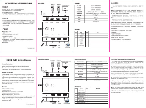
■ Please do not dismantle the equipment, avoid damaging the internal electrical component.
HDMI Type A x1 (female)
Switch way
Key switch, remote control switch
Automatic scanning interval
Default 5 seconds (time 5~999 seconds adjustable)
Resolution
safety of the user, please observe the following matters during the process of installation, use and maintenance.
■ Please do not use this product in the following places: the place of dust, soot and electric conductivity dust, corrosive gas, combustible gas; the place exposed to high temperature, condensation,wind and rain; the occasion of vibration and impact. Electric shock, fire, wrong operation can lead to damage and deterioration to the product, either;
Atlona 2x16 HDMI 切换器用户指南说明书
.................................................. 6
9.4 Unit Reset
.................................................. 6
10. Applications .................................................. 7
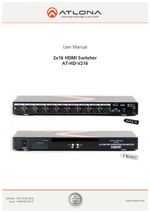
PANEL DESCRIPTION
1. Front Panel
12 3
45 6
7
1. POWER SWITCH. The power switch turns the unit on and off. The LED will illuminate red to indicate that the switcher is ON
9.1 Standby Mode
.................................................. 6
9.2 Power Off Mode
.................................................. 6
9.3 Front Panel Lock
2. Features .................................................. 2
3. Specification .................................................. 2
4. Package Contents
7. IR Extender
.................................................. 4
N6 无缝切换器 用户手册说明书

N6无缝切换器V3.0.0用户手册版权所有©2020西安诺瓦星云科技股份有限公司。
保留一切权利。
非经本公司书面许可,任何单位和个人不得擅自摘抄、复制本文档内容的部分或全部,并不得以任何形式传播。
商标声明是诺瓦科技的注册商标。
声明欢迎您选用西安诺瓦星云科技股份有限公司(以下简称诺瓦科技)的产品,如果本文档为您了解和使用产品带来帮助和便利,我们深感欣慰。
我们在编写文档时力求精确可靠,随时可能对内容进行修改或变更,恕不另行通知。
如果您在使用中遇到任何问题,或者有好的建议,请按照文档提供的联系方式联系我们。
对您在使用中遇到的问题,我们会尽力给予支持,对您提出的建议,我们衷心感谢并会尽快评估采纳。
目录1 产品概述 (1)产品简介 (1)产品特性 (1)2 外观说明 (3)前面板 (3)后面板 (4)产品尺寸 (5)3 应用场景 (6)4 液晶屏菜单操作 (7)操作说明 (7)主界面 (7)屏体配置 (9)4.3.2 输出模式 (9)4.3.3 屏体结构 (10)4.3.4 输出设置 (10)4.3.5 输出接口配置 (11)窗口设置 (11)4.4.1 窗口分屏模板 (11)4.4.2 BKG配置 (12)4.4.3 窗口配置 (13)场景设置 (14)输入设置 (15)画面控制 (15)测试画面 (16)预监选择 (17)高级设置 (18)4.10.2 系统模式 (18)4.10.3 同步模式 (18)4.10.4 AUX (18)4.10.5 Fn键设置 (19)4.10.6 返回主界面时长 (20)4.10.7 工厂复位 (20)4.10.8 HDCP开关 (20)4.10.9 硬件版本 (20)4.10.10 设备自检 (21)4.10.11 关于我们 (21)通讯设置 (21)5 V-CAN控制 (23)6 C1控制 (25)7 常见问题 (27)8 规格参数 (28)1 产品概述产品简介N6是由诺瓦科技自主研发的集视频处理,画面拼接,特效切换和多画面显示的高性能无缝切换器。
SL1 切换器用户手册说明书

WHAT IS THE SL1 SWITCH?• 113CM X 20CM X 2 CM - 45 X 7.8 X 0.8 "• 170 W MAX CONSUMPTION• 3.4 KG - 7.5 LBS• 3000°K TO 5600°K•24 VDC• FLICKER FREE AT ANY FRAME RATE •SL1 V4SL1 AC Power SupplySL1-EPS-V4Battery Mounting Plate SL1-MINI-VL-V4 or ABSL1 Driver SL1-CT-SWWDMX Driver UBB-DMXUSER MANUAL -POWERING OPTIONS• Place the Mount at the center of the SL1 and apply a quarter turn until the spring loaded pin drops in it’s lodging.• If you have purchased the SL1 with the Powerbox, you can attach the Powerbox at the back of the light before attaching the mount :1. Place the SL1 on a flat surface.2. Place the Powerbox on the back of the light, making sure the 4 feet are in their lodging.3. With an Allen Key n°4, screw the 4 spring loaded screw of the Powerbox to the SL1. Make sure the 4 screws are properly attached.• Once the Powerbox is attached you can mount any of the mounts to the Powerbox like you would on the head.1. On/Off2. DMX SWITCH• Switch between local andDMX control3. Local Indicator• If ON, the light is in local control mode 4. DMX Indicator• If ON, the light is in DMX control mode 5. 3200/DMX Addressing• In LOCAL mode, switches the CCT to 3200°K • In DMX mode, allows input ofDMX channel6. 5600/DMX Addressing• In LOCAL mode, switches the CCTto 5600°K• In DMX mode, increments the DMX digit7.DMX Signal• Red : no DMX input• Blinking Green : DMX signal recieved8. COLOR Indicator• If ON, the dimmer controls the CCT9. CCT Display10. SWITCH Button• Switch the function of the dimmer,from CCT control to INTENSITY control11. Intensity Indicator• If ON, the dimmer controlsthe intensity12. Intensity Display13. Dimmer• Changes CCT or intensity14. Power Out• Power out to the SL1 Head light15.Female Plate• Female plate for K1, K2 or HandleMount16. DMX IN - XLR517. DMX OUT - XLR518. Power IN - IEC151381124567910121314161718• Turn on the controls with the ON/OFF button.• power source (AC for the POWERBOX, for the DC/DC drivers).• If you have attached the controls at the back of the light, you can connect the cable-out directly to the controls. If you need to distance the SL1 from its controls, you can add the extension cable.CONTROLLING THE SL1 :SAFETY WARNING : Make sure power is off before connecting or disconnectingthe SL1 to the controls.• To control the brightness of the light, make sure to press the SWITCH button until the “Brightness” indicator is on. You can now control the brightness with the dimmer button.• You can switch the increment from 1% to 0.1% by pressing the dimmer button.• To switch from brightness to color temperature, press the SWITCH button once more until the “Color” indicator is on. You can now control the color of the SL1 with the dimmer button, from 3000°K to 5600°K.In local mode:The SL1 one takes 2 DMX channels, channel one is the brightness, channel 2 the color Setting up the DMX MODE :CONTROLLING THE SL1 (CONTINUED) :• Then, to control the SL1 in DMX, you need to switch from LOCAL to DMX mode. Do this by pressing the button between LOCAL and DMX. The DMX indicator will turn on when in DMX mode.• To setup the DMX address, press the first DMX button (also the 3200°K button). The first digit can be set by pushing the second DMX button (also the 5600°K button).• Press the 3200°K button again to change of digit. Repeat until all of your digits are set.• Once the address is set, the DMX indicator will blink if a DMX signal is received. Otherwise, please check your DMX signal.1. Menu• Go to the general menu 2. Back• Step back in menu• Lock/unlock UBB when pressed for 2secs.3. SWITCH• Change between CCT and intensity control4. CCT• Quickly change from 3200°k to 5600°K• Enter the preset menu to store or recall values5. Dimmer button• Press to change intensity or CCT • Select fine or coarse dimming when pressed• Navigate through the menu and push to validate6. USB plug• Upgrade the UBB’s firmware 7. 12~30VDC input8. Connector for Wifi antenna 9. Mounting plate for EPS and Battery mounts10. Attachment for shoulder strap 11. DMX IN 12. DMX OUT 13. LAN IN14. ON/OFF• Turns SL1 or MINI SWITCH ON 15. Door for antennas storage 16. Connector for Wireless DMX antenna17. 8 pins connector for SL1 SWITCH 18. 4 pins connector for Mini SWITCH1235498181712141311151610761. Connect the UBB to a power source (DMG EPS, DMG Battery mount or any 12 to 30VDC power supply)2. Connect the Mini SWITCH or SL1 SWITCH to the UBB3. Turn on the UBB by selecting which light you are powering (SL1 or Mini)Four modes are available :• LOCAL MODE• DMX MODE• Wireless DMX MODE• CUSTOM MODELOCAL MODE:DMX MODE:Control the UBB remotely with the Wireless DMXprotocol.• Make sure the Wireless DMX antenna should be intalled• Press the dimmer button to enter the DMX startnumber of the UBB• Validate by pressing goWireless DMX dot is red when no signal is received, greenwhen the UBB is connected to a Wireless DMX emitter.To synchronize with a new emitter, go back to general menu and enter Wireless DMX mode again.Control the UBB locally with the dimmer button.• Press the SWITCH button to change between CCT and intensity control• Press CCT button for a quick change between 3200°K and 5600°K• Press the dimmer button to select coarse or fineintensity tuningControl the UBB remotely by cable with the DMX protocol.• Press the dimmer button to enter the DMX startnumber of the UBB CUSTOM MODE:In custom mode the UBB acts as a translator betweendifferent protocols. It still controls the SL1 SWITCH orMini SWITCH connected to it.• Make sure the Wireless DMX antenna should be installed ifsing Wireless DMX.• Make sure the Wi-Fi antenna should be installed if using Wi-Fi.• Press the dimmer button to select data input, dataoutput and DMX address.• Validate by selecting «Go».If Wi-Fi input is selected, the UBB creates a Wi-Fi networks with the following specifications:SSID: UBB serial numberPassword: dmglumiereThese informations can be find in the “info” section of the UBB menu.Wireless DMX dot is red when no signal is received, green when the UBB is connected to a Wireless DMX emitter.• To synchronize with a new emitter, go back to general menu and enterWireless DMX mode again.CUSTOM MODE (FOLLOWING) :(...)Wi-Fi dot is red when no signal is received, green when the UBB is connected to a Wi-Fi device with an Art-Net app enabled.UPGRADING THE UBB :• Download the firmware from the DMG Lumière website:/upgrade• Copy the file to a USB stick• Insert the USB key in the UBB.If a correct file is found on the USB stick, the UBB will prompt an upgrade menu.• Select YES to upgrade• Wait for upgrade to finish. The UBB will turn off and on automatically toactivate the upgrade.INFO :Displays the firmware version, the Network name and password for the Wi-Fi mode.DMG Lumière lights or any Wireless DMX enabled lightOur wireless DMX is compatible with anypowered devices.WDMXWDMX WDMX WDMXWIFIWIFI12435876111091291. Connect the CT to a power source (DMG EPS, DMG Battery mount or any 12 to35VDC power supply)2. Connect the SL1 SWITCH to the CT3. Turn on the CT1. On/Off2. Intensity Indicator• If ON, the dimmer controlsthe intensity3. Intensity Display4. Color Indicator• If ON, the dimmer controls the CCT 5.SWITCH Button• Switch the function of the dimmer, from CCT control to INTENSITY control 6. 3200°K Addressing• Switches the CCT to 3200°K 7. 5600°K Adressing• Switches the CCT to 5600°K 8. Dimmer• Changes CCT or intensity9. Attachments for shoulder strap10.12~35 VDC input11.Mounting plate for EPS and Battery mounts12. Power Out• Power out to the SL1 Head lightCT GUIDELINESUSER MANUAL -General precautions• DMG Lumière products are made to be used by trained professionals only.DMG Lumière products are not for household use.Risk of falling• If the SL1 SWITCH, the MINI SWITCH or the MAXI SWITCH are not secured with their two security cables on the lights, there is a risk of falling and death.• Make sure the slings or chains chosen to secure the light complies with standards in the country you are in.Risk of electric shock and fire• High voltage when using with the powerbox and External power supply !• Use only the power supplies sold by DMG Lumière to power the lights.• When inputting 220V or 110V AC current, make sure the POWERBOX is connected to the ground before using.• Do not open the product. There are no user serviceable parts inside.Overheating• Do not operate the product if the ambient temperature exceeds 45° C.• Intensive use can cause the surface to become hot .• Let the product cool down completely before you handle it.• Do not cover the air vents !Intense light• Do not look at the light directlyWarnings• Stage and Studio Use Only• Dry Location Only• Hazardous Voltage• Risk of Electrical Shock• Disconnect Power Before Servicing• Not For Residential Use ApprovalsEU Safety :• EN 55015:2013• EN 61547:2009• EN 61000-3-2:2014• EN 61000-3-3:2013• EN 61000-4-2:2009• EN 61000-4-3:2006+A1:2008+A2:2010• EN 61000-4-4:2012• EN 61000-4-5:2006• EN 61000-4-6:2009• EN 61000-4-8:2010• EN 61000-4-11:2004• EN 62471FCC :• 47 CFR of part 15CSA and UL :• CSA C22.2 No. 250.4-14• CAN/CSA C22.2 No. 250.13-14• UL Standard No. 153• UL Standard No. 8750ROHS :• EPA3050B:1996• EN1122B:2011• EPA3052:1996• EPA7196A:1992• APE3540C:1996• EPA8270D:2007。
Pelco MS500系列手动视频切换器产品说明书

561C820 / REVISED 5-20-08International Standards Organization Registered Firm; ISO 9001 Quality SystemMS500 Series SwitcherMANUAL, VIDEO Product Features•Economical•4, 8, 12, 18, or 40 Inputs •Terminating or Looping •Desktop or Rack Mount•Compatible with Color or B-W Composite Video Signals•Single Monitor Output (Except 40-Position Switcher Which Has Two Monitor Outputs)•120 VAC Input Models OnlyThe MS500 Series of manual, passive switchers provide an econom-ical means of switching 4, 8, 12, 18, or 40 inputs to a single monitor. The interlocked manual push-button switches provide 75-ohm termination at each switch.The MS500L Series of manual, looping switchers provide the same functions as the MS500 manual switchers except no termination is used and connectors are provided so that the video inputs may be looped through and terminated elsewhere.Pelco has engineered a unique method of selecting over 18 inputs. By inter-wiring two sets of switches (4-position and 10-position), you can economically and reliably switch up to 40 inputs in only 1.75 inches (4.45 cm) of panel height on most models.All switchers are desktop models. Optional rack mounting kits are available.Audio follow options of single (AF) or balanced (BAF) audio are avail-able for up to 18 positions. AF switchers are equipped with SPST, nor-mally open switch closures for each position; BAF switchers haveDPDT, normally open switch closures for each position.MS504DT562Pelco, Inc. Worldwide Headquarters:3500 Pelco Way, Clovis, California 93612-5699 USAUSA & Canada Tel: (800) 289-9100 • FAX (800) 289-9150International Tel: +1 (559) 292-1981 • FAX +1 (559) MODELSMS504DT Manual switcher, 4 inputs, terminating MS508DT Manual switcher, 8 inputs, terminating MS512DT Manual switcher, 12 inputs, terminating MS518DT Manual switcher, 18 inputs, terminating MS504GDT Manual switcher, 4 inputs, illuminated buttonsMS508GDT Same as MS504GDT, 8 inputs MS512GDT Same as MS504GDT, 12 inputs MS518GDT Same as MS504GDT, 18 inputs MS504LDT Manual switcher, 4 inputs, looping MS508LDT Manual switcher, 8 inputs, looping MS512LDT Manual switcher, 12 inputs, looping MS518LDT Manual switcher, 18 inputs, looping MS540LDT Manual switcher, 40 inputs, looping MS504GLDT Manual switcher, 4 inputs, illuminated buttons, loopingMS508GLDT Same as MS504GLDT, 8 inputs MS512GLDT Same as MS504GLDT, 12 inputs MS518GLDT Same as MS504GLDT, 18 inputsMS504AF Manual switcher, 4 inputs, terminating with audio followMS508AF Manual switcher, 8 inputs, terminating with audio followMS518AF Manual switcher, 18 inputs, terminating with audio followMS504AFL Manual switcher, 4 inputs, looping, with audio followMS508AFL Manual switcher, 8 inputs, looping, with audio followMS512AFL Manual switcher, 12 inputs, looping, with audio followMS504BAF Manual switcher, 4 inputs, terminating with balanced audio followMS508BAF Manual switcher, 8 inputs, terminating with balanced audio followMS504BAFL Manual switcher, 4 inputs, looping with balanced audio followMS508BAFL Manual switcher, 8 inputs, looping with balanced audio followMS512BAFLManual switcher, 12 inputs, looping with balanced audio followVIDEOInputs4, 8, 12, 18, or 40 as indicated by the last two digits of the model number Video Connectors BNCAudio Connectors AF Switchers 1/8-inch RF phono jack BAF Switchers Terminal blockTerminationTerminated or Non-looping ModelsInput –75-ohm internal termination Output –75-ohm source termination Looping ModelsInput –High impedance looping Output –High impedance loopingELECTRICAL(Models MS500GDT, MS500GLDT, and MS540LDT)Input Voltage 120 VAC, 50/60 Hz Power Requirements 0.095 amp (11 VA)Fuse 3 AG 1/16 ASB Power Cord 3-wire grounded, 18 AWG (Model MS540LDT only)Output Amplifier One amplified output and one non-amplifiedoutput for use with MPT9000CZ/MPT9000PZ or KBD9000Gain Unity Frequency Response Flat within ±1 dB to 10 MHz Maximum Signal Level 2 Vp-pGENERALSwitching Interlocked manual push buttons Construction Cover Steel, black polyester powder coat Chassis Steel, zinc platedPanel Aluminum, black polyester powder coat Environment32° to 120°F (0° to 49°C)Dimensions/WeightAs noted below (weights approximate)CERTIFICATIONS/RATINGS•UL Listed•Meets NEMA Type 1 standardsOPTIONAL ACCESSORIESR300Rack mount kit for up to three switchers. (Factory racking available for R300 rack kits only.) 1 RU. Use with ᕡ above.RKS10Rack mount kit for single switcher. 1 RU. Use with ᕢ above.RKS20Rack mount kit for single switcher. 1 RU. Use with ᕣ above.RKS40Rack mount kit for single switcher. 2 RUs. Use with ᕤ above.Pelco and the Pelco logo are registered trademarks of Pelco, Inc.Product specifications and availability subject to change without notice.©Copyright 2008, Pelco, Inc. All rights reserved.ᕡMS504AF, MS504DT,MS504GDT, MS504GLDT, MS504LDT1.75" H x 5.3" W x 9.3" D (4.45 x 13.46 x 23.62 cm) Unit Weight: 3 lb (1.35 kg) Shipping Weight: 4 lb (1.81 kg)ᕢMS504AFL, MS504 BAF,MS504BAFL, MS508AF, MS508BAF, MS508BAFL, MS508DT, MS508GDT, MS508GLDT, MS508LDT, 1.75" H x 14.3" W x 9.3" D (4.45 x 36.32 x 23.62 cm)Unit Weight: 6 lb (2.71 kg) Shipping Weight: 8 lb (3.62 kg)ᕣMS508AFL, MS512AFL, MS512GDT, MS512GLDT, MS512LDT, MS518AF, MS518DT, MS518GDT, MS518GLDT 1.75" H x 17.12" W x 9.30" L (4.45 x 43.48 x 23.62 cm) Unit Weight: 7 lb (3.17 kg) Shipping Weight: 9 lb (4.07 kg) ᕤMS540LDT3.50" H x 17.12" W x 9.30" L (8.89 x 43.48 x 23.62 cm)Unit Weight: 9 lb (4.07 kg)Shipping Weight: 11 lb (4.98 kg)。
矩阵切换器使用说明书
矩阵切换器
Professional Matrix
前言
感谢您使用本公司矩阵切换器,使用时请注意以下事项:
1.本产品所使用电源必须有电源保护地线,输入、输出设备的电源保护地 线要为同一保护地线。确保设备的输入电源为 AC 100~240V/50Hz。
2.使用计算机控制本产品时必须保证控制计算机与本产品的连接电源保护 地线是同一个地线。
1
矩阵切换器
目录
Professional Matrix
前 言....................................................................................................................... 1 目 录....................................................................................................................... 2 一、清单、外形及安装说明 ................................................................................... 4
7
矩阵切换器
- 1、下载文档前请自行甄别文档内容的完整性,平台不提供额外的编辑、内容补充、找答案等附加服务。
- 2、"仅部分预览"的文档,不可在线预览部分如存在完整性等问题,可反馈申请退款(可完整预览的文档不适用该条件!)。
- 3、如文档侵犯您的权益,请联系客服反馈,我们会尽快为您处理(人工客服工作时间:9:00-18:30)。
科迪矩阵控制软件使用说明
第一章软件安装
本软件为绿色软件,将该科迪矩阵控制软件目录复制到硬盘上即可。
复制完成后,运行RWMP286.exe。
默认的用户名为:aaa,密码:123
第二章软件使用
运行RWMP286.exe后,会出现如下界面:
(以下图片仅供参考,软件版本以应用软件为准)
A切换画面简介:
上图中,每一个彩色圆饼处所处的交叉点位置对应一路信号的输入输出关系。
右方为输出信号(即矩阵的目的端口),上方为输入数(即矩阵的源信号端口)。
例如,上图表示输入1切换至输出1,输入2切换至输出2,......,输入16切换至输出16。
当鼠标在屏幕上移动时,对应的输入和输出路数颜色会变化,以示区别,上图中鼠标停留在输入16(in16)和输出14(out14)的位置上。
圆饼被分隔成几部分,就表示矩阵有多少层,上图中圆饼有红色、蓝色两部分,故有视频、音频两层;当只点亮其中一层时,就单独切换该层,若全部点亮,则为多层同时切换。
按钮:状态刷新按钮,点击该按钮,矩阵的所有状态将刷新一遍。
当矩阵规模较大时,刷新时间会较长(几秒至几十秒不等)。
按钮:通过点击该按钮,可以放大或缩小的大小和显示的圆饼个数。
按钮:在预置后,‘切换’为按照预置进行切换;‘取消’为取消预置键。
保存预置设置功能:。
按“增加”键,进行预置,
单击鼠标左键,如上图所示,预置切换路数,按“Done”即可按照自己定义的“Name”一栏的名称进行保存。
调用时,单击下拉菜单中选择已经预置的内容,所预置的内容通过“编辑”可以进行修改,并保存。
显示与矩阵之间的通讯数据,供专业人士参考。
B快速使用入门:
1、查询矩阵状态:
1)单路查询:鼠标左键单击屏幕右侧的输出按键,圆饼的位置就是所对应的输入路数。
2)多路查询:鼠标左键单击状态刷新按钮,所有路的状态将刷新一遍。
2、切换路数:
1)单路切换:鼠标左键双击输入、输出的交叉点位置,既将所对应的输入路切换到所对应的输出路。
鼠标左键单击输入、输出的交叉点位置,既将所对应的输入路预置到所
对应的输出路,之后按‘切换’键,即实现切换。
2)多路切换:鼠标左键单击多处输入、输出的交叉点位置,预置多路,之后按‘切换’键,即实现切换。
预置多路
点击‘切换’切换
3、锁定、解锁:
单击鼠标右键,选项中有“锁定”选项,单击它,即将该输出路数锁定。
锁定后,该输出路数不可切换。
若想切换必须先单击右键对该路进行“解锁”操作。
锁定前
锁定后
4、下拉菜单中的其他选项:
1)读矩阵配置:读取矩阵的设置并执行“刷新”操作。
2)打开:设置预置。
3)关闭:取消预置。
4)配置:设定一些软件配置,单击后出现系统设置界面。
通讯:通讯串口号选择;
速率:通讯的传输速率(不可更改);
层:矩阵的层数;(注:矩阵的层数和规模在软件启动后自动获取,一般不需要设置)输入:输入的最大路数;
输出:输出的最大路数;
使用TCP/IP通讯:
使用网口通讯时,请点击“使用TCP/IP通讯”,软件的默认IP地址为192.168.0.247(如上图),请根据使用环境或咨询网络管理员设定合理的IP地址,(也可以通过串口助手向设备发送*RI#命令读取设备的IP地址)端口选择处输入22,23,24中的一个,不支持其他的端口号。
注意:此处输入的IP地址必须与矩阵主机的IP地址一致,否则无法连通!
使用串口调试助手可以通过串口修改矩阵的IP地址,修改完成后必须对矩阵主机断电并重新上电,IP地址更改才能生效(具体串口指令请参考通讯协议的“读写IP地址指令”)。
5、定时切换的说明
选择定时切换后将出现如下界面
下面通过定时切换设置举例进行说明 (1)编辑定时切换列表区
通过对任务的插入、删除、清除的操作,编辑将要定制的任务列表。
每一列均代表在特定时间某一输入端口切换至某一输出端口。
比如,列表第一行表明,“循环1234567”周一至周日,每天的10:46:43,进行将输入端口1切换至输出端口1的操作。
在当前选中行之前插入任务
在当前选中行之后插入任务 删除当前选中行
删除所有行
(2)对单个任务的编辑 ①对切换内容的操作
注意:编辑操作必须先选中列表中的某一任务,否则操作无效。
对光标选中当前所在行进行操作
注意:
操作时必须选中某一行
通过对输入、输出的下拉选单进行指定路数的切换设置换
通过对层中的V 、A 前面的圆形标记的双击操作进行层的增减,必须至少有一层前面的圆形图标存在,代表切换某层或某几层
②对切换循环周期中日期的操作
通过对循环的下拉菜单选中已经预置好的循环种类,对应显示在右侧循环对话框中注意:
操作时必须选中某一行
对光标选中当前所在行进行操作
双击红色旗帜,
天作为预置切换的循环周期,
与左侧循环下拉菜单中不同,
对话框内显示为准进行周期切换
③对切换循环周期中时间的操作
对当前选中行进行的修改时间按操作,将显
示在上方任务列表中。
注意: 操作时必须选中某一行
对光标选中当前所在行进行操作 秒清
0操作即将该选中任务的秒清0。
简化
设定操作。
此操作同样在选定的任务中进行
(3)任务的保存与加载
将修改后的任务列表保存在指定目录
也可导入已有的任务列表添加到当前列表中。
(4)任务的启动
注意,所设置的任务,必须在设置页面中启动,并在总页面中勾选Task ,方可启动定时任务。
没有这两部分的启动,将无法进行定时的切换操作。
设置完成后,可保存任务列表,退出当前对话框。
通过对某一任务的双击操作,可以改变某一单个
任务的使能状态
也可通过“全部启动”或“全部停止”进行总的
使能和禁止的操作。
注意:启动定时切换,需要在设置中将任务列表中任务启动后
,在总 界面中,必须勾选Task 复选框
,此时右下角有红色闪动上下方向的箭头
,此时表明已启动定时切换。
6:关于输入输出信号名称的修改
如果需要修改软件上显示的输入输出端口名称,请打开title.txt 文件,编辑文件中对应的路数即可,注意要与默认的格式一致。
可修改名称。