丹佛斯变频器modbus设置
丹佛斯变频器PROFIBUS通讯配置
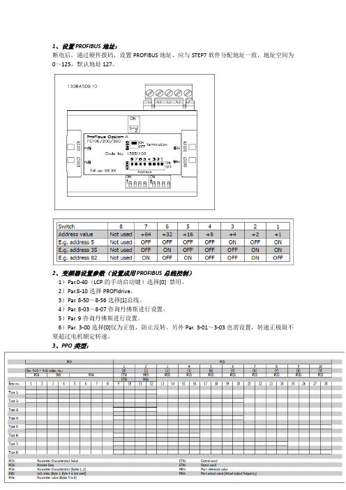
1、设置PROFIBUS地址:断电后,通过硬件拨码,设置PROFIBUS地址,应与STEP7软件分配地址一致,地址空间为0~125,默认地址127。
2、变频器设置参数(设置成用PROFIBUS总线控制)1)Par.0-40(LCP的手动启动键)选择[0] 禁用。
2)Par.8-10选择PROFIdrive。
3)Par. 8-50~8-56选择[1]总线。
4)Par. 8-03~8-07咨询丹佛斯进行设置。
5)Par. 9咨询丹佛斯进行设置。
6)Par. 3-00选择[0]仅为正值,防止反转。
另外Par. 3-01~3-03也需设置,转速正极限不要超过电机额定转速。
3、PPO类型:见上表,总共有PPO Type 1~8共8种模式。
PPO types 3、4、6、7和8用于非循环参数访问,只能访问PCD(过程控制数据),但是不能对PCV(变频器参数特征值)进行访问。
选择上述5种模式,PLC送出过程控制数据,变频器响应后返回过程状态数据。
对于过程控制数据,PCD头4个字节(图中1、2)由CTW (控制字)和MRV(主要参考值――速度)组成,用来控制电机起停以及速度给定。
下4个字节(图中3、4)写Par. 9-15[1]中设置的可以写的参数;对于状态数据,PCD头4个字节(图中1、2)由STW(状态字)和MAV(主要实际值――速度)组成,用来反应电机运行状态以及速度反馈值。
下4个字节(图中3、4)写Par. 9-16[1]中设置的可以读的参数。
后续字节为Par. 9-23中设置的参数。
PPO types 1、2、5可以对PCV(变频器参数特征值)和PCD(过程控制数据)进行读写。
所有PPO types都可以选择成Word consistent(只有PCV数据是连续的,不需要调用SFC14,15)和Module consistent(PCD,PCV数据是连续的,都有调用SFC14,15)。
4、CTW(控制字)/ STW(状态字):根据Par.8-10设置的不同可以选择PROFIdrive或者FC结构。
Danfoss变频器设置参数及说明及网络拓扑

Danfoss VLT5000系列变频器采用DP-Profbus总线控制方式,即所有的控制命令和状态反馈都是通过网络传送的。在系统中,5000系列变频器总是作为从站。每一台变频器具有唯一的DP地址。
5000系列变频器的相关知识请参考随机手册。在次主要对一些重要的参数设置进行一下说明,如果更换到变频器,请注意这些参数:
7
505
START SELECT
启动选择
SERIALPORT
总线控制
需更改
8
508
PRES.REF. SELECT
速度选择
SERIALPORT
总线控制
需更改
9
512
TELEGRAM PROFILE
电报行规
SERIALPORT
总线控制
需更改
10
804
RESPONSE AFTER BUS ERROR
断网功能
序号
参代码
功能
设定
备注
1
002
OPERATION SITE
本地/远程控制
REMOTE
远程
默认值
2
200
OUT FREQ RNG/ROT
输出频率范围/方向
132 HZ BOTH DIRECT
132 HZ双向
需更改
3
205
MAX REFERENCE
最大参考点
50.00
默认值
此值必须和上位设置的最大值相对应。
302变频器的设置参数及说明
序号
参代码
功能
设定
备注
1
0-02
电动机速度单位
1
需更改
2
DANFOSS_FC302变频器设置说明_DP

DANFOSS FC302变频器操作概要在对变频器进行设置时,最简单的方法是使用图形化本地控制面板(LCP),如图所示:1JUKAO19 1JStatus1234rpm 10^A~~^3,5Hz43,5^图17图形化本地控制面板LCP该控制面板分为四个功能组:1. 带有状态行的图形显示器。
2. 菜单键和指示灯:用于更改参数和切换显示功能3. 导航键和指示灯(LED)4. 操作键和指示灯(LED)所有数据都显示在图形LCP显示屏中,显示[Status](状态)时,最R-nOK多可以显示5项操作数据。
显示行: a. 状态行:显示图形和图形的状态信息b.第1-2行:操作员数据行,显示用户定义或选择的数据。
通过 按[Status ](状态)键,最多可以再增加一行。
c.状态行:用于显示文本的状态信息。
二、 DANFOSS FC302变频器电气接线图 电气接线图如下图所示:图18电气接线图(Li)~~ ---------------------------- Swilch Mode PowerSupply10Vdc 1如岛24Vdc+二:J77Z7/77768+1OVdc 0/4-205-0040咖缶>(N P N )(PNP)M/OUT)DN^TflFmlnalMdH/OUT)RS-4U)r(NPh) (PNP)aN/l = 0-20m^OFF/d=0-1DV(NPh) fPNP)Brake resis tor-1OVdc +1OVdc(o IN)powsr Input(COM RS-4S5)18 (D57 (D IN)二1OYdt+lOVdc 0/4-2052 [D-C mA54 (A IN):l?S-4fl5 * Inferf UCBS8D1 o庙PE ③£可二’:Analag OutpLtJLHJ 0/4-20 mAHE"㈣抽 (W) M百eFFSi三、DANFOSS FC302变频器参数设置A、1-**负载/电动机在本地控制面板(LCP)上,按键,进入参数设定界面,设定完成。
丹佛斯变频器参数设置

丹佛斯变频器参数设置1. 介绍丹佛斯变频器是一种能够调节电机转速和输出频率的装置,广泛应用于各种工业领域。
为了实现最佳性能和运行效果,合理的参数设置是非常重要的。
本文档将介绍丹佛斯变频器的参数设置方法,帮助用户正确配置变频器,以实现预期的控制效果。
2. 参数设置步骤2.1. 进入参数设置界面首先,您需要进入丹佛斯变频器的参数设置界面。
您可以通过以下步骤进行操作:1.打开变频器控制面板,通常位于变频器的前面板。
2.寻找“参数设置”按钮,并点击进入参数设置界面。
2.2. 基本参数设置在参数设置界面中,您将看到各种参数选项。
以下是一些基本参数的设置建议:•频率(Frequency):设置输出频率,通常以赫兹(Hz)为单位。
根据您的应用需求,选择适当的频率范围。
•电压(Voltage):设置输出电压,通常以伏特(V)为单位。
确保电压设定与电机额定电压一致。
•过载保护(Overload Protection):设置变频器的过载保护功能,以保护电机免受过载损坏。
根据电机的额定功率和负载情况,设置适当的过载保护参数。
2.3. 控制参数设置控制参数设置是影响变频器控制性能的重要因素。
以下是一些常见的控制参数设置:•加速时间(Acceleration Time):设置电机从启动到达设定频率所需的时间。
较短的加速时间可提高启动速度,但可能会对电机和机械系统造成冲击和损坏。
•减速时间(Deceleration Time):设置电机从运行状态减速到停止所需的时间。
适当的减速时间可以减少机械系统的损坏风险。
•PID控制参数:PID控制是一种常用的闭环控制方法,可以提高电机的响应速度和稳定性。
根据具体的应用需求,设置适当的PID控制参数,如比例(P)、积分(I)和微分(D)增益。
2.4. 保护参数设置保护参数设置是用来保护变频器和电机免受损坏的重要措施。
以下是一些常见的保护参数设置:•过流保护(Overcurrent Protection):设置电机的过流保护值,当电机电流超过这个值时,变频器将采取相应的保护措施,如降低输出频率或停机。
丹佛斯变频器modbus通讯
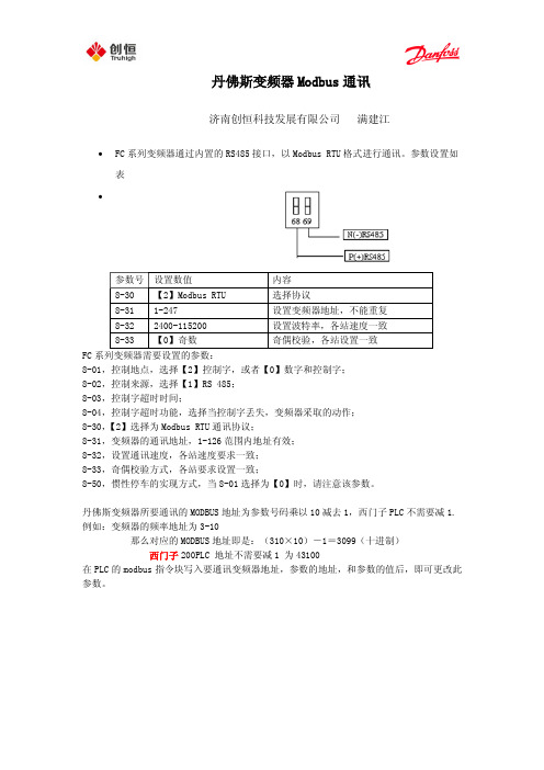
丹佛斯变频器Modbus通讯济南创恒科技发展有限公司满建江∙FC系列变频器通过内置的RS485接口,以Modbus RTU格式进行通讯。
参数设置如表∙FC系列变频器需要设置的参数:8-01,控制地点,选择【2】控制字,或者【0】数字和控制字;8-02,控制来源,选择【1】RS 485;8-03,控制字超时时间;8-04,控制字超时功能,选择当控制字丢失,变频器采取的动作;8-30,【2】选择为Modbus RTU通讯协议;8-31,变频器的通讯地址,1-126范围内地址有效;8-32,设置通讯速度,各站速度要求一致;8-33,奇偶校验方式,各站要求设置一致;8-50,惯性停车的实现方式,当8-01选择为【0】时,请注意该参数。
丹佛斯变频器所要通讯的MODBUS地址为参数号码乘以10减去1,西门子PLC不需要减1. 例如:变频器的频率地址为3-10那么对应的MODBUS地址即是:(310×10)-1=3099(十进制)西门子200PLC 地址不需要减1 为43100在PLC的modbus指令块写入要通讯变频器地址,参数的地址,和参数的值后,即可更改此参数。
∙电报结构(十六进制)∙地址字段包含8位数据,有效的地址范围为0-247(十进制),0为广播模式;1-247对相应地址的从站进行寻址。
功能字段包含8位数据,有效地代码范围为1-FF,功能字段用于在主站和从站之间发送消息。
当从主站向从站发送时,功能字段为主站的控制字;当从从站向主站传送时,功能字段为从站的状态字。
∙数据字段,是由几组字节两个十六进制数字(00至FF)构成,根据不同的功能代码,数据字段包含的位长、作用不一,针对常用的功能代码,举例如下:∙1、功能代码=1,读取线圈状态∙ 2、功能代码=5,写入单个线圈数值∙ 3、功能代码=F,写入多个线圈数值∙线圈及位的意义。
地址0-31为主站写入用控制位,32-63为从站返回的状态位,如下表所示:∙例如,使电机启动并运转在50%*最大参考值的报文如下∙其中位的个数为 20H=32个位,也就是从00地址起始到31为止的位;字节数,是指写入数值为4个字节;写入数值 047C 对应00-16位,在传送时低位在前,因此为7C 04;2000 对应16-31位,50%*最大参考值,在传送时低位在前,因此为00 20;对于停止,应发043C代码4、功能代码=3,读取保持寄存器状态,保存寄存器保持2字节(即16位)∙ 5、功能代码=6,写入单个寄存器∙ 6、功能代码=10,写入多个寄存器数值∙寄存器列表:∙例如,当要读取3-41,加速时间时,需要写的报文:∙计算参数3-41的地址 3-41 → 341*10-1=3409 → D51(十六进制);保持寄存器状态都为双字节,因此在字个数位置应该为 2 ;正常情况下,变频器返回的报文为,∙012C 为读出的加速度时间,转换成十进制并考虑到控制单位,得到加速时间为3秒。
丹佛斯(Danfoss) FC101和FC102变频器Novenco控制用户指南说明书

Pure competence in air.927665-0FREQUENCY CONVERTERS DANFOSS FC 101 AND FC 102NOVENCO CONTROL USER GUIDE927665-0GBFrequency converters Danfoss FC 101 and FC 102Novenco control user guideContents1.General2.Wire configuration3.First time run after installation4.Configuration of FC101 converter5.Configuration of FC102 converter6.Modbus configuration7.Reference documentation8.Patents and trademarks9.Declaration of conformity1.GeneralThe procedures in this guide serve as examples of how to control the Danfoss FC 101 and FC 102 frequency con-verters in combination with Novenco fans.Please read all relevant parts of this complete guide.Procedures and methods in this guide should be fol-lowed for the warranty to remain valid.2.Wire configurationCheck wires are correctly connected•Check that a wire connects the terminals no. 12 and 27 in the frequency converter.•Connect a control wire to terminal no. 18 in the fre-quency converter. The terminal must pull high (24V) to activate the converter.•Check the signal wire is connected to terminal no. 53. For voltage control the signal levels are 0 - 10V and for current control the levels are 4 - 20mA.•Check that ground is connected to terminals no. 20 and 55.Table 1.Icons in guideFigure 2Terminal block set up for current control3.First time run after installationHow to check the installation is correct1.Check the installation is powered off on the mainswitch.2.Check the fan and frequency converter are in-stalled correctly. Refer to the installation and maintenance guides for the fan and frequency converter.3.Power on the installation at the main switch. Thefrequency converter starts in idle mode.4.Push Hand On on the local control panel (LCP)on the frequency converter. This activates the fan rotor.5.Check the direction of rotation is consistent withthe arrows on the fan casing.6.Turn off the installation at the main switch.7.Connect the start signal wire to terminal no. 18.8.Voltage or current mode:Connect the reference wire to terminal no. 53.Modbus mode:Connect the reference wires to terminals no. 68 and 69.4.Configuration of FC101 converterThe converter is set up for voltage mode as standard. The minimum speed is indicated with 0V and the max-imum speed with 10V.Figure 3Wire diagram for the FC101+10 V DC4.1Change from voltage to current con-trolHow to change the FC101 to current control1.Push the Menu button on the LCP on the fre-quency converter.2.Push the ↓ and ↑ buttons to navigate to the Wiz-ard. Push OK to select.3.Push ↓ to navigate to the following menu item.6-19 Terminal 53 mode[1] Voltage mode4.Push OK to access and use the ↓ and ↑ to selectcurrent mode.5.Push OK to accept.The frequency converter now operates in current mode for control signals. The minimum speed is indicated with 4mA and the maximum speed with 20mA.5.Configuration of FC102 converter The converter is set up for voltage mode as standard.The minimum speed is indicated with 0V and the max-imum speed with 10V.Figure 4Wire diagram for the FC1025.1Change from voltage to current con-trolHow to change the FC102 to current control1.Remove the screw that holds the lid on the fre-quency converter.2.Pull out the LCP with a straight pull.3.Locate the text A53 U - I.4.Push the button from position U to I with ascrewdriver.5.Put the LCP back.6.Attach the lid and insert the screw.The frequency converter now operates in current mode for control signals. The minimum speed is indicated with 4mA and the maximum speed with 20mA. 6.Modbus configurationAll parameters are accessible through Modbus RTU (Re-mote Terminal Unit) either directly or via PCD (Process Data).To setup the Modbus RTU1.Push the Menu button two times.2.Push ↓ to navigate to8-** Comm. and Options.3.Push OK.4.Push ↓ to navigate to 8-3 FC port settings.5.Push OK.6.Push OK again.7.Push ↓ to navigate to [2] Modbus RTU.8.Push OK to confirm.9.Push ↓ to navigate down and check the followingsettings.•Address•Baud Rate•Parity / Stop bit•Minimum Response Delay•Maximum Inter-char..10.Push OK to select, the ↓ and ↑ buttons to changeand push OK to confirm settings.Write and start-stop notes•PCD: It is possible to configure up to 64 parame-ters in PCDs.Write PCDs in par. 8-42.xx, and read PCDs in par.8-43.xx. These PCDs are accessible via holdingregisters 28xx and 29xx.•Write control word: Par. 8-42.0 and par. 8-42.1 areset to the control word and as reference, respec-tively. Set par. 8-42[2-63] to the par. no. to write to.•Start-stop: Write the control word to register 2810to start or stop the converter.Read notes•The reference register is 2811 with 0 - 4000hex(0-100%).•Read status word: Par. 8-43.0 and par. 8-43.1 areset to status word and main actual value, respec-tively. Set par. 8-43[2-63] to the par. no. to readfrom.Figure 5Location of terminal 53Bit Bit value = 0Bit value = 100Reference value External selection LSB01Reference value External selection MSB02DC brake Ramp03Coasting No coasting04Quick stop Ramp05Hold output frequency Use ramp06Ramp stop Start07No function Rest08No function Jog09Ramp 1Ramp 210Data invalid Data valid11Relay 01 open Relay 01 active12Relay 02 open Relay 02 active13Parameter set-up Selection LSB14< Not used >< Not used >15No function ReverseTable 2.Control word bit positions•Read status word: Read the status word from reg-ister 2910.Other notes•Set the speed, i.e. the main actual value, with reg-ister 2911.•Read the configuration of par. 8-43.3.. with regis-ter 2912.•To configure a PCD to read a 32bit parameter re-quires configuration of two consecutive PCDs to the same parameter. For example, the parameter 16-10 Power [kW] is a 32bit integer, which may be configured in par. 8-43.2 and 8-43-3, or par. 8-43.4 and 8-43.5 and so on.The sizes of the different parameters are available in the programming guide.•To address parameters directly use the register no. = parameter no. x 10. For example, the par. 16-90 is accessible via register no 16900.•Some PLCs have 0 offsets, which means the value 1 must be subtracted from the register no. For ex-ample, reg. 2810 is 2809 etc.00Control not ready Control ready 01Drive not ready Drive ready 02Coasting Enable 03No error Trip04No error Error (no trip)05Reserved -06No error Triplock 07No warningWarning08Speed reference Speed = reference 09Local operationBus control10Out of frequency limit Frequency limit ok 11No operation On operation12Drive ok Stopped, auto start 13Voltage ok Voltage exceeded 14Torque ok Torque exceeded 15Timer okTimer exceededTable 3.Status word bit positionsNovenco Building & Industry A/S Industrivej 22Tel. +45 70 77 88 994700 Naestved Denmark7.Reference documentation•Danfoss Operating guideVLT ® HVAC basic drive FC 101Publication no. MG18AA02, 04/2018•Danfoss Programming guide VLT ® HVAC basic drive FC 101Publication no. MG18B502, 04/2018•Danfoss Design guideVLT ® HVAC basic drive FC 101Publication no. MG18C802, 04/2018•Danfoss Operating guide VLT ® HVAC drive FC 102Publication no. MG16O202, 04/2018•Danfoss Programming guide VLT ® HVAC drive FC 102Publication no. MG11CE02, 03/2015•Danfoss Design guide VLT ® HVAC drive FC 102Publication no. MG11BC02, 06/20148.Patents and trademarksNovenco ®ZerAx ® is a registered trademark of Novenco Building & Industry A/S.AirBox™ and NovAx™ are trademarks of Novenco Building & Industry A/S.VLT ® is a registered trademark of Danfoss A/S.The ZerAx ® processes of manufacture, technologies and designs are patented by Novenco A/S or Novenco Building & Industry A/S.Pending patents include Brazil no. BR-11-2012-008607-3, BR-11-2012-008543-3, BR-11-2012-008545-0, BR-11-2014-002282-8 and BR-11-2014-002426-0; India no. 4140/CHENP/2012, 4077/CHENP/2012, 821/CHENP/2014 and 825/CHENP/2014; PCT no. EP2012/064908 and EP2012/064928; South Korea no. 10-2012-7012154.Granted patents include Canada no. 2.777.140,2.777.141, 2.777.144, 2.832.131 and 2.843.132; China no. ZL2010800458842, ZL2010800460965, ZL2010800464275 and ZL2012800387210; EU no. 2488759, 2488760,2488761, 2739860 and 2739861; India no. 312464; South Korea no. 10-1907239, 10-1933724, 10-1980600 and 10-2011515; US no. 8.967.983, 9.200.641, 9.273.696 B2,9.683.577 and 9.926.943 B2. Granted designs include Bra-zil no. BR-30-2012-003932-0; Canada no. 146333; China no. 1514732, 1517779, 1515003, 1555664 and 2312963; EU no. 001622945-0001 to 001622945-0009 and 001985391 - 0001; India no. 246293; South Korea no. 30-0735804; US no. D665895S, D683840S, D692119S, D704323S,D712023S, D743018S, D755363S, D756500S, D821560S and D823452S.The NovAx Basic jet fans manufacturing processes, technologies and designs are patented by Novenco A/S or Novenco Building & Industry A/S.Granted patents include EU no. 2387670 and United Arab Emirates no. 1372. Granted designs include EU no. 001069884-0003, 001069884-0008, 001069884-0010, 001069884-0013, 001069884-0017, 001069884-0019, 001069884-0022, 001069884-0026 and 001069884-0028; United Arab Emirates no. D223/2009.The CGF jet fans designs are patented by Novenco A/S or Novenco Building & Industry A/S.Granted designs include EU no. 001610643-0001 to 001610643-0005.Copyright © 2016 - 2020,Novenco Building & Industry A/S.All rights are reserved.9.Declaration of conformityRefer to the declaration information in the documenta-tion for the fans and frequency converters.Figure 6QR code to this guide onPure competence in air. ttt͘EKs E Kͳ h/> /E'͘ KD。
丹佛斯变频器本地控制设置
丹佛斯变频器本地控制
设置
标准化管理处编码[BBX968T-XBB8968-NNJ668-MM9N]
丹佛斯变频器VLT2900本地控制参数设定步骤:
1.变频器上电,同时按动【QUICK MENU】+【+】进入菜单模式利用【+/-】键滚动显
示各参数找到
2.进入002本机/远程操作中本机操作(LOCAL)设置【1】
3.013本机控制按参数100的本机控制(闭环)
(LOC CTRL/AS P100) 设置【3】
4.参数203(参考值/反馈范围)设置为【0】或【1】
5.电机加速时间进入207取值加速时间30秒
6.电机减速时间进入208取值减速时间30秒
7.按动【QUICK MENU】利用【+/-】键滚动可快速进入003电机频率要改变数据值先
按【CHANGE DATA】利用【+/-】键改变参数值。
8.每次更改完数据后按【CHANGE DATA】来确认储存已改的参数值。
丹佛斯变频器参数设置
丹佛斯变频器参数设置丹佛斯变频器参数设置丹佛斯变频器是一种能够调节电机运行频率的设备,它能够实现电机的无级调速,使其按照不同的负载需求运行,达到节能降耗、提高生产效率的目的。
要想丹佛斯变频器达到最佳的运行效果,需要对其参数进行适当的设置。
本文将就丹佛斯变频器的参数设置进行详细介绍。
1.基本参数设置(1)工作/停止方式:选择工作方式时,需根据实际需要进行选择,一般有V/F控制、向量控制和直接转矩控制三种方式可选。
停止方式的设置也需根据实际需求确定,有自由停机、减速停机、急停等多种方式可选。
(2)电源输入:输入电压需与电机额定电压相同,同时还需进行频率设置。
(3)最大频率设置:最大频率设置应根据具体负载情况选择,通常应不大于电机额定转速。
(4)最小频率设置:最小频率的设置需考虑电机低速时的转矩输出,应根据实际负载和逆变器能力进行确定。
丹佛斯变频器支持多种通信协议,如MODBUS、PROFIBUS-DP、CANOPEN等。
通信参数主要包括通信地址、波特率、校验位等。
(1)加速时间和减速时间:加速时间和减速时间的设置需根据实际负载情况选择,不能过快或过慢,以免对电机造成损害。
(2)PID调节:在向量控制模式下,需进行PID(比例、积分、微分)参数的设置,以实现快速响应、精确控制的目的。
(3)倍率设置:可根据实际负载情况进行倍率设置,常见的倍率包括电压倍率和转矩倍率。
为了保护丹佛斯变频器和电机的安全运行,需对保护参数进行设置。
(1)过电流保护:可设置电机最大输出电流,以避免因负载过大而损坏电机。
(3)过压保护:当输入电压超过预设范围时,需自动停机以防止对电机造成伤害。
(5)过热保护:当丹佛斯变频器发生过热时,需自动停机,以避免设备损坏。
综上所述,丹佛斯变频器的参数设置需根据具体负载情况而定,需要谨慎选择和调整,以确保设备能够正常、安全、高效地运行。
丹佛斯变频器MODBUSRTU的通讯
关于丹佛斯变频器MODBUS RTU的通讯发布时间: 2008-11-18 12:03:40 被阅览数: 476 次一:MODBUS? RTU规约概术??? MODBUS规约是MODICOM公司开发的一个为很多厂商支持的开放规约MODBUS 协议是应用于电子控制器上的一种通用语言。
通过此协议,控制器相互之间、控制器经由网络(例如以太网)和其它设备之间可以通信。
它已经成为一通用工业标准。
有了它,不同厂商生产的控制设备可以连成工业网络,进行集中监控。
此协议定义了一个控制器能认识使用的消息结构,而不管它们是经过何种网络进行通信的。
它描述了控制器请求访问其它设备的过程,如果回应来自其它设备的请求,以及怎样侦测错误并记录。
它制定了消息域格局和内容的公共格式。
???? 二:丹佛斯MODBUS RTU概念????? DANFOSS 变频器在自动化领域中有着大量的应用,作为变频器专业供应商,DANFOSS 一直把提高产品的通信应用水平作为其重点工作之一。
基于MODBUS RTU协议,DANFOSS 开发了相应的控制集成卡,通过这种集成卡DANFOSS变频器可以以MODBUS RTU 协议方便与SCADA和HMI等设备集成在一起。
????????? DANFOSS? VLT2800或VLT5000(已停产)系列变频器MODBUS RTU通讯与FC300系列变频器的通讯类似?三:S7-200、台达PLC与丹佛斯变频器接线:?S7-200 DSUB9??????? DANFOSS???? 3----+------------------68???? 8------------------------69?台达PLC正信号+---------------------68负信号-----------------------69?四:丹佛斯变频器的参数设置?1.VLT5000(已停产)或VLT2800变频器相关通讯参数设置:561#---------2----RTU协议500#---------1----485地址为1???????????501#---------5----9600570#---------0----1停止位,EVEN校验其他参数使用初始化参数?2.FC300或FC51变频器相关通讯参数设置:8-30-----1----RTU协议8-3地址8-32----------波特率8-33----------1停止位,EVEN校验??五:PLC的程序例子如果该变频器加了MCO305同步卡或PROFIBUS卡,此通讯功能被占用。
丹佛斯变频器modbus设置
•FC系列变频器通过内置的RS485接口,以Modbus RTU格式进行通讯。
参数设置如表
•
参数号设置数值内容
8-30 【2】Modbus RTU选择协议
8-31 1-247 设置变频器地址,不能重复
8-32 2400-115200 设置波特率,各站速度一致
8-33 【0】奇数奇偶校验,各站设置一致
FC系列变频器需要设置的参数:
8-01,控制地点,选择【2】控制字,或者【0】数字和控制字;
8-02,控制来源,选择【1】RS 485;
8-03,控制字超时时间;
8-04,控制字超时功能,选择当控制字丢失,变频器采取的动作;
8-30,【2】选择为Modbus RTU通讯协议;
8-31,变频器的通讯地址,1-126范围内地址有效;
8-32,设置通讯速度,各站速度要求一致;
8-33,奇偶校验方式,各站要求设置一致;
8-50,惯性停车的实现方式,当8-01选择为【0】时,请注意该参数。
丹佛斯变频器所要通讯的MODBUS地址为参数号码乘以10减去1,西门子PLC 不需要减1.
例如:变频器的频率地址为3-10
那么对应的MODBUS地址即是:(310×10)-1=3099(十进制)西门子200PLC 地址不需要减1 为43100
在PLC的modbus指令块写入要通讯变频器地址,参数的地址,和参数的值后,即可更改此参数。
济南创恒满建江。
- 1、下载文档前请自行甄别文档内容的完整性,平台不提供额外的编辑、内容补充、找答案等附加服务。
- 2、"仅部分预览"的文档,不可在线预览部分如存在完整性等问题,可反馈申请退款(可完整预览的文档不适用该条件!)。
- 3、如文档侵犯您的权益,请联系客服反馈,我们会尽快为您处理(人工客服工作时间:9:00-18:30)。
FC系列变频器通过内置的RS485接口,以Modbus RTU格式进行通讯。
参数设置如表
参数号设置数值内容
8-30【2】Modbus RTU选择协议
8-311-247设置变频器地址,不能重复
8-322400-115200设置波特率,各站速度一致
8-33【0】奇数奇偶校验,各站设置一致
FC系列变频器需要设置的参数:
8-01,控制地点,选择【2】控制字,或者【0】数字和控制字;
8-02,控制来源,选择【1】RS 485;
8-03,控制字超时时间;
8-04,控制字超时功能,选择当控制字丢失,变频器采取的动作;
8-30,【2】选择为Modbus RTU通讯协议;
8-31,变频器的通讯地址,1-126范围内地址有效;
8-32,设置通讯速度,各站速度要求一致;
8-33,奇偶校验方式,各站要求设置一致;
8-50,惯性停车的实现方式,当8-01选择为【0】时,请注意该参数。
丹佛斯变频器所要通讯的MODBUS地址为参数号码乘以10减去1,西门子PLC不需要减1.
例如:变频器的频率地址为3-10
那么对应的MODBUS地址即是:(310×10)-1=3099(十进制)
西门子200PLC 地址不需要减1 为43100
在PLC的modbus指令块写入要通讯变频器地址,参数的地址,和参数的值后,即可更改此参数。
济南创恒满建江。