英国阿尔法Alphasense硫化氢传感器 H2S-A1
硫化氢检测仪的使用方法
硫化氢检测仪的使用方法
硫化氢检测仪通常是用于测量空气中硫化氢(H2S)浓度的仪器。
以下是一般的使用方法:
1. 准备:确保仪器已经经过校准并处于工作状态。
检查传感器是否完好,并确认电池电量足够。
2. 设置:根据需要,设定测量单位和报警阈值。
一般来说,硫化氢检测仪会配备一个液晶显示屏,可以用按钮或旋钮设置相关参数。
3. 打开仪器:按下开关按钮或旋转开关,打开检测仪。
4. 预热:检测仪通常需要一段时间进行预热,以确保传感器的准确测量。
等待预热完成。
5. 进行测量:将检测仪的传感器暴露在待测空气中,可以通过吸气泵或直接靠近气体源进行检测。
等待一段时间,直到测量结果稳定并显示在屏幕上。
6. 结果读取:读取屏幕上显示的硫化氢浓度值。
确保浓度值在安全范围内。
如果超过设定的报警阈值,仪器可能会发出声音或光闪烁以示警告。
7. 关闭仪器:使用完毕后,按下关闭按钮或旋转关闭开关,将检测仪关闭。
注意事项:
- 在操作过程中,确保按照仪器的说明书进行正确、安全的操作。
- 确保仪器定期校准,以保证测量结果的准确性。
- 使用仪器时,应遵循相关的安全操作规程,戴好个人防护装备。
- 如果检测到空气中硫化氢浓度过高,应采取必要的措施确保人员安全,如迅速撤离危险区域并报警。
H2S传感器应用电路
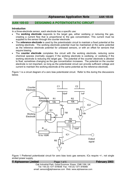
AAN 105-03DESIGNING A POTENTIOSTATIC CIRCUITIntroductionIn a three-electrode sensor, each electrode has a specific use:• The working electrode responds to the target gas, either oxidising or reducing the gas, creating a current flow that is proportional to the gas concentration. This current must be supplied to the sensor through the counter electrode.• The reference electrode is used by the potentiostatic circuit to maintain a fixed potential at the working electrode. The working electrode potential must be maintained at the same potential as the reference electrode potential for unbiased sensors, or with an offset for sensors that require biasing.• The counter electrode completes the circuit with the working electrode, reducing some chemical species (normally oxygen) if the working electrode is oxidising, or oxidising if the working electrode is reducing the target gas. The potential of the counter electrode is allowed to float, sometimes changing as the gas concentration increases. The potential on the counter electrode is not important, so long as the potentiostat circuit can provide sufficient voltage and current to maintain the working electrode at the same potential as the reference electrode. Figure 1 is a circuit diagram of a zero bias potentiostat circuit. Refer to this during the discussions below.Figure 1 Preferred potentiostat circuit for zero bias toxic gas sensors. ICs require +/-, not single ended power supply.© Alphasense Limited Page 1 of 5 February 2003A typical potentiostat circuit consists of three parts:1 Control circuit with bias voltage, if required2 Current measuring circuit3Shorting FET to connect the working electrode to the reference electrode when power is off Control CircuitThe control op amp (IC2 in figure 1) provides the current to the counter electrode to balance the current required by the working electrode.The inverting input into IC2 is connected to the reference electrode and must not draw any significant current from the reference electrode. An op amp with an input bias current of less than 5nA is recommended.When switching on the circuit, the depletion mode JFET (Q1 in Fig 1)goes to a high impedance state and IC2 provides the current to maintain the working electrode at the same potential as the reference electrode. Any offset due to the input offset voltage in IC2 will therefore cause a sudden shift in potential at switch-on. Toxic gas sensors have a large capacitance, so significant currents can flow for small potential shifts, so ensure that your op amp has a low offset voltage, certainly less than 1 mV and preferably less than 100µV; also check the op amp offset voltage at the maximum usage temperature.Typically, for an oxidisable gas (such as CO) with a platinum reference electrode, the counter electrode will be -300 to -400mV from the ground potential. However, if hydrogen ions rather than oxygen molecules are reduced, then the potential could be as large as -1.05V. Also, reducing gases (such as NO2 or Chlorine) force the counter electrode to oxidise water, evolving oxygen; in this case the potential relative to the reference electrode is between +600 and +800 mV, depending on the type of reference electrode. Therefore, you must allow IC2 enough voltage swing to drive the counter electrode to the required potential and with sufficient current demanded by the sensor. If the circuit is unable to do this, then extreme non-linearities will occur at higher concentrations. It is best to allow ±1.1V swing on IC2 (plus any imposed bias voltage). This means that for a CO or H2S sensor the counter electrode wants to be typically -350 mV below the ground point, so IC2 needs a negative supply. If you are using a single ended low voltage power supply, pay particular attention to the available output swing on the op amp at the required current.Table 1 below shows the maximum generated steady state current for each type of sensor. At full scale no sensor generates more than 210µA, but allow at least 500µA for a general purpose circuit, although this can be decreased for specific, well tested sensor/ circuit combinations. Beware- when switching the circuit ON in the presence of an electroactive gas or when a new sensor is first connected, the sensor may give a surge current of several mA that may cause IC1 to clamp, depending on the current drive capacity of IC1; it is unlikely that IC1 can maintain the virtual earth on its inverting input with a high feedback resistor during such a high current transient. Always connect the sensor before powering the circuit.Circuit stability and noise reduction in the control circuit relies on R1, R2, C1 and C2; C2 may not be necessary for certain op amps. If eliminating C2, then C1 may be increased- between 10 and 100 nF. Suggested op amps are OP90 (single op amp) and OP 296 (dual op amp).© Alphasense Limited Page 2 of 5 February 2003Bias voltageNormally, Alphasense toxic gas sensors are operated in the zero bias mode; however, certain sensors, such as NO sensors, require a bias voltage: typically ±150 or 300mV for an NO sensor. Alternatively, sensor cross-sensitivity to certain gases can be enhanced by adding a bias voltage.BEWARE! performance can also be degraded if you bias incorrectly! Remember that biasing a normally unbiased sensor may damage the sensor and certainly voids the sensor warranty. Consult Alphasense for further advice.If you wish to inject a bias voltage then also ensure that your bias voltage is stable: changes of even a few mV can affect sensitivity to gases and rapid changes in the bias voltage by only a mV will generate transient effects for up to hours on the sensor output. A simple method of biasing the sensor is shown in figure 2 below. The 10K load resistor to ground can be removed to reduce the current on V bias.Biasing should be maintained when the instrument is switched off - this is normally accomplished by using a button cell battery that remains on at all times. In this case, the input offset of IC2 is not critical, but its drift with temperature etc. must be kept small.Current Measuring CircuitThe measuring circuit is a single stage op amp (IC1) in a transimpedance configuration; the sensor current is reflected across R4, generating an output voltage relative to the virtual earth. C3 reduces high frequency noise. It is sometimes desirable to use two opamp stages to give the required output; the first stage should use a low value for R4 to allow the circuit to oppose the sensor current in transient conditions, followed by a second voltage gain stage to give the required output. The input offset voltage of IC1 will add to the sensor bias voltage (as the working electrode will be offset from 0V) so the input offset should be kept low. Remember that the generated current can be either positive or negative: sensors that oxidise at the working electrode (e.g. CO) generate a © Alphasense Limited Page 3 of 5 February 2003current into IC2, while reducing working electrodes (e.g. Cl2 or NO2) sink a current. So for the second case, ensure that IC2 has adequate current sinking capability.The measuring circuit uses a combination of the (load resistor (R load) plus internal sensor resistance) and the (internal sensor capacitance) to establish an RC circuit; the selection of R load is a compromise between fastest response time (low resistance R load) and best noise (high resistance R load): this RC circuit affects both the rms noise and the response time: the response time increases linearly with increasing R load resistance, while noise decreases rapidly with increasing R load resistance. If you need highest resolution, then forfeit fast response time. Likewise, if fast response time is critical, then reduce the resolution of your display or sample the signal faster and average over several readings in software to eliminate jitter. Due to the low impedance nature of the circuit, it is better to use an opamp with low noise current (usually at the expense of noise voltage)to get the best overall noise performance.As sensor current flows through R load, there will be a small change to the sensor bias potential. This has the effect of increasing the sensor settling time as the sensor will require a short time to re-stabilise when gas is applied, but this transient will normally not be seen except at high gas concentrations and high R load resistance.Refer to Table 1 below to calculate the required gain for your measuring circuit. If your detector/ instrument does not use the full scale of the sensor, then simply multiply the Sensitivity by your Range to determine the maximum current from the sensor. Since the sensitivity is the typical value, allow 20% more than the typical full scale output into your A/D converter.Sensor FullScale(ppm)Sensitivity(nA/ppm)(typical)Full Scaleoutput(µA)Full Scaleoutput(V)Calibrationpoint(ppm)CO-BF, CO-B1, CO-BX1,000100100 1.00 400 CO-AF1,00070700.70400 CO-AX2,00065130 1.30400 CO-AE 10,00030300 3.00 2,000 CO-DF1,00040740.74400 H2S-AH 501,200600.60 20 H2S-BH502,000850.8520 H2S-A1 100750750.75 20 H2S-B1200370740.7420 H2S-BE2,00090180 1.80 400 H2S-AE2,000105210 2.10400 H2S-D1100140140.1420 SO2-AF20500100.10 20 SO2-BF100350350.3520 SO2-AE2,00070140 1.40400 NO2-A1 20-3508-0.08 10 NO2-B120-75022-0.2210 NO2-AE200-35070-0.75100 NO-A1,-B1250400100 1.0050 NO-AE1,000100100 1.00400 Cl2-A120-3708-0.0710 CL2-B120-900220.2210 Table 1. List of output parameters and calibration point for Alphasense toxic gas sensors.© Alphasense Limited Page 4 of 5 February 2003Shorting FETIt is normal practice to add a shorting FET for unbiased sensors so that the reference and working electrodes are shorted together (with a residual resistance of a few tens of ohms) when power is removed from the circuit. This ensures that the working electrode is maintained at the same potential as the reference electrode when the circuit is switched off. The shorting FET is normally open circuit as long as power is applied. This “zero bias” state ensures that when you switch the circuit back on, the sensor is ready immediately. If you do not use a shorting FET and leave the sensor open circuit when the circuit is off, the toxic gas sensor will take a few hours to stabilise when next switched on.If you are supplying a bias voltage through IC2, then when you switch off the circuit, the sensor will be zero biased and hence when you reapply a bias voltage it will take a significant time (up to several hours) for the sensor to re-establish equilibrium. It is recommended that, for biased circuits, the bias voltage be maintained on at all times and the shorting FET not used. This will not affect the operating life of the sensor.The JFET (Q1) should be a p-type FET. Recommended FET types include surface mount or TO-92 packages as per Table 2 below.Manufacturer Product Code TypeSiliconix SST177Surface MountSiliconix J175TO-92Siliconix J176TO-92Siliconix J177TO-92Fairchild J175TO-92Table 2. Recommended p-FETs for short circuiting reference and working electrodes when the potentiostat circuit is off.Noise, RFI/EMI ScreeningIdeally, the measuring and controlling op amps in a potentiostat are fitted directly underneath the sensor to keep the shortest leads because of the low impedance and low sensor currents. Alphasense Application Note AAN 103 gives further advice on reducing noise and improving RFI/EMI screening.Sensor CalibrationNote that toxic gas sensor sensitivities are variable,typically ±15%. So you must calibrate in software to correct for sensor-to-sensor sensitivity variations. Alphasense maintains a database of the sensitivity of every sensor tested at Alphasense, but remember that sensitivity will drift downwards with time, typically 0.5% to 2% per month, depending on the sensor type, relative humidity and gas concentration/ temperature conditions. See Application Note AAN 108 for more information.It is also normal to correct for temperature dependence of the sensitivity; zero current is not normally temperature corrected, but for measurements requiring high accuracy at low concentrations, contact Alphasense for advice.© Alphasense Limited Page 5 of 5 February 2003。
硫化氢气体检测仪工作原理分析

硫化氢气体检测仪工作原理分析介绍硫化氢气体检测仪是一种可用于检测空气中硫化氢浓度的仪器设备。
由于硫化氢是一种臭鸡蛋味的有毒气体,容易引起人体中枢神经系统的损伤和死亡,因此,硫化氢气体检测仪在化工、制药、环保等工业领域使用得非常广泛。
本文将会从硫化氢气体检测仪的工作原理进行分析。
硫化氢气体检测仪的工作原理硫化氢气体检测仪的工作原理主要基于双极性半导体传感器,采用了化学传感技术。
传感器的灵敏度随着气体浓度的增加而不断提高。
传感器可以在不同的温度下工作,使它们更加适用于不同的工业环境。
下面是硫化氢气体检测仪的详细工作原理:1.空气搜集器首先,空气被搜集器中的泵子吸入,经过滤网和冷却器,完全去除较大的杂质颗粒,并降低空气温度,以确保空气纯净度和检测精确度。
由此得到的空气,将会和燃料气体以非稀释方式混合在一起。
2.燃料电极搜集器中的混合气体被输送到燃料电极上,与燃料电极上的电化学反应发生,使得燃料电极上形成一定浓度的氢离子(H),如下所示:H2 + 2e- -> 2 H+3.检测电极检测电极由双极性半导体材料构成。
由于检测电极与燃料电极之间的距离非常接近,当氢离子(H)与空气中的硫化氢分子(H2S)相互作用时,会产生一定的电信号,并通过检测电极上传到微处理器中进行反馈处理。
4.反馈处理微处理器将检测到的信号进行反馈处理,得到空气中硫化氢的浓度,以及相关的报警信息。
当检测到空气中的硫化氢浓度超过一定的阈值时,硫化氢气体检测仪将立即发出声音和光线警报,通知用户先行撤离。
总结本文从硫化氢气体检测仪的工作原理进行了详细分析。
硫化氢气体检测仪的工作原理主要基于双极性半导体传感器,采用了化学传感技术。
通过合理的空气搜集、燃料电极和检测电极的结构设计以及微处理器的反馈处理,硫化氢气体检测仪实现了对空气中硫化氢浓度的监测和报警。
硫化氢气体检验方法

硫化氢气体检验方法
硫化氢(H₂S)是一种有毒气体,因此需要进行检测以确保环境和工作场所的安全。
以下是一些用于检测硫化氢气体的常见方法:
1.传感器检测器:这是最常见和便捷的检测方法之一。
传感器检
测器通常是手持式的,可以携带到需要检测的地方。
这些检测
器使用化学传感器或电化学传感器,可以快速、准确地检测硫
化氢浓度。
一些传感器检测器还可以提供声音或视觉警告以示
警报。
2.气体检测管:气体检测管是一种使用简便的检测方法,通过颜
色变化来指示硫化氢浓度。
用户将一端打开,将其置于待检测
气体中,通过观察管内试剂颜色变化来判断气体浓度。
3.气体检测仪器:高级的气体检测仪器通常用于长期或定期的气
体监测,尤其在工业环境中。
这些设备可以实时监测硫化氢浓
度,并记录数据。
一旦浓度超过设定的安全水平,检测仪器将
发出警报。
4.固相吸附管:固相吸附管是一种简单但有效的气体检测方法。
用户将吸附管置于空气中,硫化氢会被吸附到管中的吸附剂上。
然后,用户将吸附剂送到实验室进行分析,以确定硫化氢浓度。
5.颗粒计数器:这是一种检测空气中硫化氢颗粒浓度的方法。
颗
粒计数器使用激光或其他技术来计算颗粒数量,从而确定硫化
氢的浓度。
在进行硫化氢气体检测时,务必遵循安全操作规程,并使用经过校
准和合格的检测设备。
如果在工作中发现高浓度的硫化氢,必须立即采取适当的措施,例如通风或撤离,以确保工作环境的安全。
现代传感器技术-8-化学量传感器-2016

2019/11/24
15
8 化学传感器
8.2.3 电化学式气体传感器
原理:电化学式气体传感器利用电化学原理将感受的气体 转换成可用输出信号。 分类:按电解质的不同可分为液体电解质和固体电解质, 而液体电解质又分为电流型和电位型。 1)电流型液体电解质气体传感器 电流型气体传感器:以电化学电池中工作电极与对比电极 之间响应电流为检测信号的气体传感器。它将气体与电解 质溶液反应而产生的电解电流作为传感器输出。 (1) 原电池(伽伐尼电池)型气体传感器 被检测气体在原电池中能产生自发电化学反应的气体传感 器称为“伽伐尼电池型”气体传感器。它通过检测电流来检 测气体的体积分数。
理想的气体传感器需具备以下条件:
① 选择性检测某种单一气体,对其他气体不响应或低响应.
② 对被测气体灵敏度高,能检测允许范围内的气体浓度.
③ 对检测信号响应快,重复性好.
④ 长期工作稳定性好.
⑤ 使用寿命长.
⑥ 成本低,使用维护方便。
2019/11/24
6
8 化学传感器
8.2.1 气体传感器概述
3)气体传感器的选用
2019/11/24
8
8 化学传感器
8.2.2 半导体式气体传感器
2)典型电阻式气敏元件 (1) SnO2气敏元件
以典型N型半导体材料SnO2为基材制备,是目前应用最 广的一种气敏元件;检测对象包括CH4、C3H8、CO, C2H5OH、H2S等可燃性气体和呼出气体中的酒精、NO等。 相对其他氧化物半导体气敏元件的特点: ①工作温度低。其最佳工作温度在300℃以下,可节约能源 并延长气敏元件的使用寿命。 ②在一般检测范围内(被测气体体积分数为102~104 L/L), 其电阻率变化范围大,输出信号强,无需高倍放大,因而 信号处理较方便。
硫化氢传感器

硫化氢传感器:一项重要的环境保护技术近年来,环境保护已经成为了全球各国政府和民间团体的热点话题。
随着工业化和城市化的快速发展,大量的有害气体和化学物质排放给环境带来巨大的威胁。
其中,硫化氢被认为是一种高度有害的气体,对人类身体健康和自然生态环境都带来了不可避免的危害。
为了有效地控制和减轻硫化氢对环境的影响,的研发和应用显得尤为重要。
一、的基本原理是用于检测并 quant 转硫化氢浓度的一种设备。
通常工作于一定的温度、湿度和大气压等条件下。
它们的基本结构通常由传感元件、放大器、显示器和控制电路等部分组成。
传感元件一般采用半导体、电化学或红外光学等不同的技术,它们具备不同的检测速度、灵敏度和电子学特性。
其中,半导体是一种最常见的传感器,它是用玻璃或石英管封装一个半导体材料,通过半导体材料与空气接触并发生化学反应,从而测量硫化氢浓度。
电化学则是采用电化学原理测量硫化氢气体的浓度,它们的精度和灵敏度一般比半导体高。
红外线则是利用硫化氢特殊的吸收光谱进行测量,测量精度比较高且对其他气体的干扰较小。
目前研发中的微机电系统(MEMS)具有更高的灵敏度和稳定性。
二、的应用范围硫化氢被广泛应用于生物制造、化学工业、碳化物制造、纺织加工、食品加工、医疗废物处理等领域。
在饲养场等生产领域中,硫化氢是由动物粪便、糞尿、沼气等发酵物质释放出来的。
在化工和制药工业中,硫化氢是生产过程中常见的废气之一。
硫化氢气体浓度高、味道难闻、易燃易爆,如果时间长、浓度过高的话,会对人体、环境产生非常严重的危害。
应用得相当广泛,主要目的是用于环保、安全、减少人力、物力资源浪费等。
以生产领域为例,可以用于检测饲养场的沼气,从而有效地控制有害气体的排放,保护当地生态环境。
在化工和制药工业中,可用于检测和控制生产过程中的硫化氢排放,避免对员工身体健康和环境的影响。
此外,在卫生保洁、医疗等方面,也有着广泛的应用。
三、的发展前景在全球环保政策的倡导下,已经被广泛应用于各个领域。
硫化氢H2S浓度探头

硫化氢H2S浓度探头硫化氢H2S浓度探头产品描述:硫化氢H2S浓度探头适用于各种环境和特殊环境中的硫化氢H2S浓度和泄露,在线检测及现场声光报警,对危险现场的作业安全起到了预警作用,此仪器采用进口的电化学传感器和微控制器技术,具有信号稳定,精度高,重复性好等优点,防爆接线方式适用于各种危险场所,并兼容各种控制器,PLC,DCS等控制系统,可以同时实现现场报警和远程监控,报警功能,4-20mA标准信号输出,继电器开关量输出。
硫化氢H2S浓度探头产品特性:进口电化学传感器具有良好的抗干扰性能,适用寿命8年。
采用先进微处理技术,响应速度快,测量精度高,稳定性和重复性好。
检测现场具有具有现场声光报警功能,气体浓度超标即时报警,是危险场所作业的安全保障。
4现场带背光大屏幕LCD显示,直观显示气体浓度,类型,单位,工作状态等。
5独立气室,更换传感器无须现场标定,传感器关键参数自动识别。
6全量程范围温度数字自动跟踪补偿,保证测量准确性。
检测气体:空气中的硫化氢H2S检测范围:0~100ppm,0~200ppm,0~1000ppm,0~1000ppm,0~5000ppm,100%LEL可选。
分别率:0.01ppm(0~100ppm);0.1ppm(0~1000ppm);1ppm(0~10000ppm以上);0.1LEL.工作方式:固定式连续工作,扩散式,管道式,流通时,泵吸式可选。
检测误差:≦1%(F.S)响应时间:≦10S输出信号:电流信号输出4-20MA报警方式:2路无源节点信号输出,报警点可设置。
工作环境:-20℃~50℃(特殊要求:(-40℃~+70℃)相对湿度:≦90%RH工作电压:DC12~30V传感器寿命:3年防爆形式:探头变送器及传感器均为隔爆型。
防爆等级:Exd II CT6连接电缆:三芯电缆(单根线径≧1.5mm);建议选用屏蔽电缆。
连接距离:≦1000m.防护等级:IP65.外形尺寸:183X143X107mm.重量:1.5Kg.硫化氢H2S浓度探头简单介绍:硫化氢H2S浓度探头●自动温度补偿,零点,满量程漂移补偿●防高浓度气体冲击的自动保护功能●全软件校准功能,用户也可自行校准,用3个按键实现,操作简单●二线制4-20mA输出硫化氢H2S浓度探头应用场所医药科研、制药生产车间、烟草公司、环境监测、学校科研、楼宇建设、消防报警、污水处理、工业气体过程控制石油石化、化工厂、冶炼厂、钢铁厂、煤炭厂、热电厂、、锅炉房、垃圾处理厂、隧道施工、输油管道、加气站、地下燃气管道检修、室内空气质量检测、危险场所安全防护、航空航天、军用设备监测等。
硫化氢电化学传感器说明书
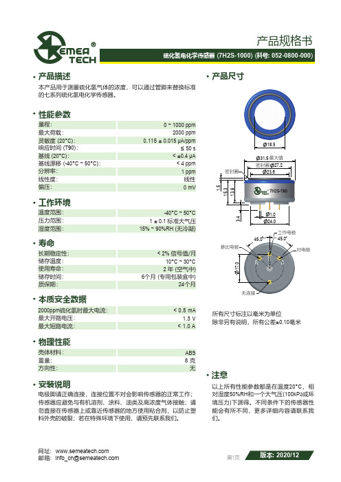
产品尺寸· 产品描述· 工作环境· 寿命· 本质安全数据· 物理性能· 安装说明·· 产品规格书最大荷载:灵敏度 (20°C ):响应时间 (T 90):基线 (20°C ):量程:温度范围:最大短路电流:最大开路电压: 2000ppm 硫化氢时最大电流:REV.: 2016-01性能参数·注意湿度范围:长期稳定性:储存温度:使用寿命:储存时间:24个月6个月 (专用包装盒中)ABS 分辨率:基线漂移 (-40°C ~ 50°C ):线性度:偏压:线性15% ~ 90%RH (无冷凝)2 年 (空气中)1 ± 0.1 标准大气压-40°C ~ 50°C 10°C ~ 30°C 以上所有性能参数都是在温度20°C ,相对湿度50%RH 和一个大气压(100kPa 或环境压力)下测得。
不同条件下的传感器性能会有所不同,更多详细内容请联系我们。
8 克无< 0.5 mA 1.3 V < 1.0 A网址: 邮箱: *********************重量:方向性:壳体材料: 第1页版本: 2020/120 mV< ±0.4 μA 0 ~ 1000 ppm ≤ 50 s< 4 ppm 2000 ppm 1 ppm0.115 ± 0.015 μA/ppm< 2% 信号值/月压力范围:质保期:电极脚请正确连接,连接位置不对会影响传感器的正常工作;传感器应避免与有机溶剂、涂料、油类及高浓度气体接触;请勿直接在传感器上或靠近传感器的地方使用粘合剂,以防止塑料外壳的破裂;若在特殊环境下使用,请预先联系我们。
本产品用于测量硫化氢气体的浓度,可以通过管脚来替换标准的七系列硫化氢电化学传感器。
- 1、下载文档前请自行甄别文档内容的完整性,平台不提供额外的编辑、内容补充、找答案等附加服务。
- 2、"仅部分预览"的文档,不可在线预览部分如存在完整性等问题,可反馈申请退款(可完整预览的文档不适用该条件!)。
- 3、如文档侵犯您的权益,请联系客服反馈,我们会尽快为您处理(人工客服工作时间:9:00-18:30)。
H2S-A1 Performance Data
Figure 2 Sensitivity Temperature Dependence
110
Technical Specification
% sensitivity (referenced to 20 OC)
105
Figure 2 shows the variation in sensitivity caused by changes in temperature. This data is taken from a typical batch of sensors. The mean and ± 95% confidence intervals are shown.
Mean "+95% conf." "-95% conf."
100
95
90
85
80 -30 -20 -10 0 10 20 30 40 50
Temperature (OC)
Figure 3 Zero Temperature Dependence
0.5 0.4 0.3
Zero output, referenced to 20oC (equivalent ppm)
78 to 93 100 to 110 <± 0.2 <± 0.2 <-20 <-25 <4 <10 <1.5 <0.2 <0.5 <0.1
KEY SPECIFICATIONS Temperature range Pressure range Humidity range Storage period Load resistor Weight
°C kPa % rh continuous months @ 3 to 20°C (stored in sealed pot) Ω (recommended) g
-30 to 50 80 to 120 15 to 90 6 10 to 47 <6
深圳市深国安电子科技有限公司
地址:广东省深圳市龙华新区牛栏前大厦C507 蒋小姐:134 2876 2631 电话:86 755-85258900 网址:www.singoan.com www.singoan.com.cn www.shenguoan.com
0.2 0.1 0 -20 -10 0 10 -0.1 -0.2 -0.3 -0.4 -0.5 Mean "+95 %conf." "-95 % conf." 20 30 40 50
Figure 3 shows the variation in zero output caused by changes in temperature, expressed as ppm gas equivalent. This data is taken from a typical batch of sensors. The mean and ± 95% confidence intervals are shown.
ENVIRONMENTAL Sensitivity @ -20°C Sensitivity @ 50°C Zero @ -20°C Zero @ 50°C CROSS SENSITIVITY NO2 Cl2 NO SO2 CO H2 C2H4 NH3 sensitivity sensitivity sensitivity sensitivity sensitivity sensitivity sensitivity sensitivity
H2S-A1 Hydrogen Sulfide Sensor
Figure 1 H2S-A1 Schematic Diagram
Technical Specification
All dimensions in millimetres (± 0.1mm)
Top View PERFORMANCE Sensitivity Response time Zero current Resolution Range Linearity Overgas limit LIFETIME Zero drift Sensitivity drift Operating life
Temperature (OC)
Figure 4 Sensitivity Long Term Stability
900 800 700
Output (nA/ppm)
600 500 400 300 200 100 0 0 500 1000
Figure 4 shows the excellent long term stability of the H2S-A1, which results from the combination of a patented design, superior electrochemistry and good process control.
% (output @ -20°C/output @ 20°C) @ 20ppm % (output @ 50°C/output @ 20°C) @ 20ppm ppm equivalent change from 20°C ppm equivalent change from 20°C % measured gas @ 10ppm % measured gas @ 10ppm % measured gas @ 50ppm % measured gas @ 20ppm % measured gas @ 400ppm % measured gas @ 400ppm % measured gas @ 400ppm % measured gas @ 20ppm NO2 Cl2 NO SO2 CO H2 C2 H 4 NH3
Bottom View
Side View 550 to 875 <25 <± 0.3 <0.05 100 0 to -4 500 <0.1 <3 >24
nA/ppm in 20ppm H2S t90 (s) from zero to 20ppm H2S ppm equivalent in zero air RMS noise (ppm equivalent) ppm H2S limit of performance warranty ppm error at full scale, linear at zero and 20ppm H2S maximum ppm for stable response to gas pulse ppm equivalent change/year in lab air % change/year in lab air, monthly test months until 80% original signal (24 month warranted)
Time (days)
2000
2500
深圳市深国安电子科技有限公司
地址:广东省深圳市龙华新区牛栏前大厦C507 蒋小姐:134 2876 2631 电话:86 755-85258900 网址:www.singoan.com www.singoan.com.cn www.shenguoan.com