冲压模具设计中英文对照外文翻译文献
冲压弯曲件冲压模具设计说明书(包含中英翻译)
冲压弯曲件冲压模具设计摘要随着中国工业不断地发展,模具行业也显得越来越重要。
本文针对支架弯曲件的冲裁工艺性和弯曲工艺性,分析比较了成形过程的三种不同冲压工艺(单工序、复合工序和连续工序),确定用一幅级进模完成落料、冲孔和一幅单工序模完成弯曲的工序过程。
介绍了支架弯曲件冷冲压成形过程,经过对支架的批量生产、零件质量、零件结构以及使用要求的分析、研究,按照不降低使用性能为前提,将其确定为冲压件,用冲压方法完成零件的加工,且简要分析了坯料形状、尺寸,排样、裁板方案,冲压工序性质、数目和顺序的确定,进行了工艺力、压力中心、模具工作部分尺寸及公差的计算,并设计出模具。
还具体分析了模具的主要零部件(如冲孔凸模、落料凸模、卸料装置、弯曲凸模、垫板、凸模固定板等)的设计与制造,冲压设备的选用,凸凹模间隙调整和编制一个重要零件的加工工艺过程。
列出了模具所需零件的详细清单,并给出了合理的装配图。
通过充分利用现代模具制造技术对传统机械零件进行结构改进、优化设计、优化工艺方法能大幅度提高生产效率,这种方法对类似产品具有一定的借鉴作用。
关键词:支架,模具设计,级进模,冲孔落料,弯曲Stamping Bending Stamping Mold DesignABSTRACTWith China's industrial developing constantly, mold industry is becoming more and more important. Based on the stent bending blanking process and bending process, Comparative analysis of the process of forming three different stamping process (single processes, complex processes and continuous processes) confirm completion of the blanking, punching and a single procedure completed the bending modulus processes. On the cover of the cold bending stents,right after the cover of the mass production, quality components, and the use of structural components of the analysis, research, in line with lower performance prerequisite to the identification of stampings, Stamping method used to complete the processing components, and a brief analysis of the blank shape, size, layout, the conference board, stamping processes in nature, number and sequence determination. For the process, the center of pressure, the die size and the tolerance of the calculation, design mold. Also analyzes the mold of the main components (such as mould, punch hole punch, unloader device, punch, plate, bending plate etc) design and manufacturing, stamping equipment selection, punch-gap adjustment and establishment of a vital parts machining process. Die requirements set out a detailed list of parts, and gives a reasonable assembly. By fully utilizing modern manufacturing technology to mold traditional mechanical parts for structural improvements, design optimization, process optimization methods can greatly enhance production efficiency, the method of similar products have some reference.KEY WORDS: stents,mold design,progressive die,punching blanking, bending目录前言 (1)第1章对加工零件的工艺分析 (5)1.1零件分析 (5)1.1.1 冲压件的工艺分析 (5)1.1.2 分析比较和确定工艺方案 (6)1.1.3 弯曲件的工艺分析 (7)第2章冲裁模 (8)2.1 冲压模具的工艺分析与设计计算 (8)2.2 工作力的计算 (10)2.2.1 落料力 (10)2.2.2 冲孔力 (10)2.2.3 卸料力 (11)2.2.4 推料力 (11)2.2.5 冲侧刃缺口的力 (12)2.2.6 总冲压力 (12)2.3 确定模具压力中心 (12)2.4确定凸、凹模刃口尺寸 (15)2.4.1 冲孔部分 (16)2.4.2 落料部分 (17)2.5 成型零部件的结构设计 (18)2.5.1冲孔凸模结构设计 (18)2.5.2冲孔凸模结构设计 (19)2.5.3凹模结构设计 (19)2.6 模具的整体设计 (20)2.6.1选择模具结构形式 (20)2.6.2操作方式 (20)2.6.3模架类型 (21)2.6.4定位方式的选择 (21)2.6.5卸料和出料方式的选择 (21)2.6.6导向方式选择 (21)2.6.7定位零件设计 (21)2.6.8导料板设计 (21)2.6.9卸料板设计 (22)2.6.10垫板设计 (23)2.6.11模柄选择 (24)2.6.12凸模固定板的设计 (25)2.6.13导柱导套选择 (26)2.6.14模座选择 (26)2.6.15螺钉、销钉的选用 (27)2.6.16装配图设计 (27)2.6.17模架的选取 (27)2.6.18冲压设备的选择 (28)第3章弯曲模 (29)3.1冲压零件的工艺分析 (29)3.2模具结构 (29)3.3必要的计算 (29)3.3.1弯曲力的计算 (30)3.3.2弹顶器的计算 (31)3.3.3回弹量的确定 (31)3.3.4弯曲凸模的圆角半径 (31)3.3.5弯曲凹模的圆角半径及其工作部分的深度 (31)3.3.6弯曲凸模和凹模之间的间隙 (32)3.3.7弯曲凸模和凹模宽度尺寸的计算 (32)3.4模具总体设计 (33)3.4.1凹模结构设计 (33)3.4.2凸模结构设计 (34)3.4.3定位板结构设计 (34)3.4.4模柄选择 (35)3.4.5模架的选取 (35)3.4.6销钉的选用 (36)3.4.7压力机的选取 (36)3.4.8装配图设计 (37)第4章模具制造技术要求 (38)4.1表面粗糙度及标准 (38)4.2加工精度 (39)4.2.1尺寸偏差 (39)4.2.2形位公差 (39)4.2.3配合要求 (39)结论 (41)谢辞 (42)参考文献 (43)外文资料翻译 (45)前言冷冲压是利用安装在压力机上的冲模对材料施加压力,使其产生分离或塑性变形,从而获得所需要零件(俗称冲压件或冲件)的一种压力方法。
模具外文翻译(冲压)
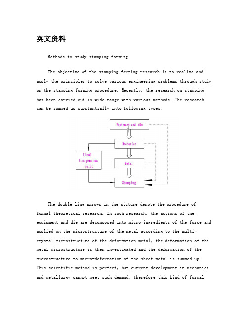
英文资料Methods to study stamping formingThe objective of the stamping forming research is to realize and apply the principles to solve various engineering problems through study on the stamping forming procedure. Recently, the research on stamping has been carried out in wide range with various methods. The research can be summed up substantially into following types.The double line arrows in the picture denote the procedure of formal theoretical research. In such research, the actions of the equipment and die are decomposed into micro-ingredients of the force and applied on the microstructure of the metal according to the multi-crystal microstructure of the deformation metal, the deformation of the metal microstructure is then investigated and the deformation of the microstructure to macro-deformation of the sheet metal is summed up. This scientific method is perfect, but current development in mechanics and metallurgy cannot meet such demand, therefore this kind of formaltheoretical research is still in burgeoning, and is not applicable in practice.Since the formal theoretical research method encounters formidable difficulty, a kind of simplified theoretical method appears in the research field of the stamping forming. The characteristic of this kind of research method is denoted by continuous line in the picture, whichis the main trend of the recent research. This research assumes metal as the ideal homogeneous solid and simplifies the property parameters, the boundary conditions and the blank geometrical parameters of the metal, the stamping process and principle are analyzed and described by mathematical method. Naturally, the assumptions adopted in the analysis would induce some deviation between the real stamping process and its simulation. The result is certainly approximate and does not reflect the real stamping process completely. Especially in analyzing complex stamping forming, this theory is not so valid. In recent years, due to the development of the finite element method and computer technology, this kind of theoretical method has greatly progressed, it shows applicable prospect even in analyzing complex stamping forming. The application of this kind of theoretical method mainly focuses on some special stamping deformation investigation, and it is expected that more achievements can be obtained in the fundamental principle of stamping forming. On the other hand, due to the simplification and assumptions, experiments are indispensable to test the validity of this theory.The third method to study stamping forming is shown by dashed dotted line in the picture. The characteristic of this method is that ignoring the deformation process of the blank under the action of the load during stamping forming conditions (including the structure of thedie, the geometrical parameters of the die working portion and the properties of the stamping equipment) with the final results of the stamping forming. It is a rational empirical method, and widely used in stamping technology filed in recent years. This method is intuitional, simple and easy to be adopted by engineers, but it cannot be used to reveal the real procedure of the stamping deformation, so it is not the radical method to investigate the principles of the stamping forming more thoroughly and its usage is strictly limited.The fourth method to study stamping forming is denoted by dashed line in the picture. Based on the fundamental knowledge of the mechanics and metallurgy, the essential characteristics and principle of the stamping forming are investigated to solve the practical problems in stamping process. In comparison with other plastic processes, the characteristics of the stamping forming, the principles of the sheet metal deformation are unique. So this method has definitely aim and the analysis results can be used directly to solve different problems in stamping forming. The characteristics and effects of this research of this research of this research method are illustrated by following examples.(1)The sequence of the stamping process can be decided by the trend rule of the stamping deformation.(2)According to the rule of uniform velocity distribution in the outer flange of the deformation zone during multi-pass deep drawing for the box parts, the shape and dimension of the blank during process sequence can be calculated. Therefore the calculation the for deep boxparts of the multi-pass deep drawing technology is based on scientific foundation to improve the technique level of stamping forming.(3)According to the research on the wrinkle during the sheet metal forming caused by non-uniform tensile and shearing force, a new research field is developed beyond the traditional compressive instability theory. The results obtained offer an effective measure to cope directly with wrinkle during stamping forming.(4)The theory of sorting stamping forming based on the characteristics of the stamping deformation and mechanics and mechanics is an easy approach to systematize of the stamping forming, and can be used to deepen the investigation on stamping forming limit, to point out a clear and definite direction for improve the stamping forming limit.Above examples indicate that this method is closely relevant to the real stamping forming process. It can be used to analyze and solve the stamping forming problems effectively. Although this method is in the junior stage, mainly focusing on the qualitative analysis for stamping forming now . With the constant progress of this method and combined with modern mechanics, the breakthrough of this method is expected to further enhance stamping forming technology.。
外文翻译-冲压模具设计成型方面
英文翻译4 Sheet metal forming and blanking4.1 Principles of die manufacture4.1.1 Classification of diesIn metalforming,the geometry of the workpiece is established entirely or partially by the geometry of the die.In contrast to machining processes,ignificantly greater forces are necessary in forming.Due to the complexity of the parts,forming is often not carried out in a single operation.Depending on the geometry of the part,production is carried out in several operational steps via one or several production processes such as forming or blanking.One operation can also include several processes simultaneously(cf.Sect.2.1.4).During the design phase,the necessary manufacturing methods as well as the sequence and number of production steps are established in a processing plan(Fig.4.1.1).In this plan,the availability of machines,the planned production volumes of the part and other boundary conditions are taken into account.The aim is to minimize the number of dies to be used while keeping up a high level of operational reliability.The parts are greatly simplified right from their design stage by close collaboration between the Part Design and Production Departments in order to enable several forming and related blanking processes to be carried out in one forming station.Obviously,the more operations which are integrated into a single die,the more complex the structure of the die becomes.The consequences are higher costs,a decrease in output and a lower reliability.Fig.4.1.1 Production steps for the manufacture of an oil sumpTypes of diesThe type of die and the closely related transportation of the part between dies is determined in accordance with the forming procedure,the size of the part in question and the production volume of parts to be produced.The production of large sheet metal parts is carried out almost exclusively using single sets of dies.Typical parts can be found in automotive manufacture,the domestic appliance industry and radiator production.Suitable transfer systems,for example vacuum suction systems,allow the installation of double-action dies in a sufficiently large mounting area.In this way,for example,the right and left doors of a car can be formed jointly in one working stroke(cf.Fig.4.4.34).Large size single dies are installed in large presses.The transportation of the parts from one forming station to another is carried out mechanically.In a press line with single presses installed one behind the other,feeders or robots can be used(cf.Fig.4.4.20 to 4.4.22),whilst in large-panel transfer presses,systems equipped with gripper rails(cf.Fig.4.4.29)or crossbar suction systems(cf.Fig.4.4.34)are used to transfer the parts.Transfer dies are used for the production of high volumes of smaller and medium size parts(Fig.4.1.2).They consist of several single dies,which are mounted on a common base plate.The sheet metal is fed through mostly in blank form and also transported individually from die to die.If this part transportation is automated,the press is called a transfer press.The largest transfer dies are used together with single dies in large-panel transferpresses(cf.Fig.4.4.32).In progressive dies,also known as progressive blanking dies,sheet metal parts are blanked in several stages;generally speaking no actual forming operation takes place.The sheet metal is fed from a coil or in the form of metal ing an appropriate arrangement of the blanks within the available width of the sheet metal,an optimal material usage is ensured(cf.Fig.4.5.2 to 4.5.5). The workpiece remains fixed to the strip skeleton up until the laFig.4.1.2 Transfer die set for the production of an automatic transmission for an automotive application-st operation.The parts are transferred when the entire strip is shifted further in the work flow direction after the blanking operation.The length of the shift is equal to the center line spacing of the dies and it is also called the step width.Side shears,very precise feeding devices or pilot pins ensure feed-related part accuracy.In the final production operation,the finished part,i.e.the last part in the sequence,is disconnected from the skeleton.A field of application for progressive blanking tools is,for example,in the production of metal rotors or stator blanks for electric motors(cf.Fig.4.6.11 and 4.6.20).In progressive compound dies smaller formed parts are produced in several sequential operations.In contrast to progressive dies,not only blanking but also forming operations are performed.However, the workpiece also remains in the skeleton up to the last operation(Fig.4.1.3 and cf.Fig.4.7.2).Due to the height of the parts,the metal strip must be raised up,generally using lifting edges or similar lifting devices in order to allow the strip metal to be transported mechanically.Pressed metal parts which cannot be produced within a metal strip because of their geometrical dimensions are alternatively produced on transfer sets.Fig.4.1.3 Reinforcing part of a car produced in a strip by a compound die setNext to the dies already mentioned,a series of special dies are available for special individual applications.These dies are,as a rule,used separately.Special operations make it possible,however,for special dies to be integrated into an operational Sequence.Thus,for example,in flanging dies several metal parts can be joined together positively through the bending of certain metal sections(Fig.4.1.4and cf.Fig.2.1.34).During this operation reinforcing parts,glue or other components can be introduced.Other special dies locate special connecting elements directly into the press.Sorting and positioning elements,for example,bring stamping nuts synchronised with the press cycles into the correct position so that the punch heads can join them with the sheet metal part(Fig.4.1.5).If there is sufficient space available,forming and blanking operations can be carried out on the same die.Further examples include bending,collar-forming,stamping,fine blanking,wobble blanking and welding operations(cf.Fig.4.7.14 and4.7.15).Fig.4.1.4 A hemming dieFig.4.1.5 A pressed part with an integrated punched nut4.1.2 Die developmentTraditionally the business of die engineering has been influenced by the automotive industry.The following observations about the die development are mostly related to body panel die construction.Essential statements are,however,made in a fundamental context,so that they are applicable to all areas involved with the production of sheet-metal forming and blanking dies.Timing cycle for a mass produced car body panelUntil the end of the 1980s some car models were still being produced for six to eight years more or less unchanged or in slightly modified form.Today,however,production time cycles are set for only five years or less(Fig.4.1.6).Following the new different model policy,the demands ondie makers have also changed prehensive contracts of much greater scope such as Simultaneous Engineering(SE)contracts are becoming increasingly common.As a result,the die maker is often involved at the initial development phase of the metal part as well as in the planning phase for the production process.Therefore,a much broader involvement is established well before the actual die development is initiated.Fig.4.1.6 Time schedule for a mass produced car body panelThe timetable of an SE projectWithin the context of the production process for car body panels,only a minimal amount of time is allocated to allow for the manufacture of the dies.With large scale dies there is a run-up period of about 10 months in which design and die try-out are included.In complex SE projects,which have to be completed in 1.5 to 2 years,parallel tasks must be carried out.Furthermore,additional resources must be provided before and after delivery of the dies.These short periods call for pre-cise planning,specific know-how,available capacity and the use of the latest technological and communications systems.The timetable shows the individual activities during the manufacturing of the dies for the production of the sheet metal parts(Fig.4.1.7).The time phases for large scale dies are more or less similar so that this timetable can be considered to be valid in general.Data record and part drawingThe data record and the part drawing serve as the basis for all subsequent processing steps.They describe all the details of the parts to be produced. The information given in theFig.4.1.7 Timetable for an SE projectpart drawing includes: part identification,part numbering,sheet metal thickness,sheet metal quality,tolerances of the finished part etc.(cf.Fig.4.7.17).To avoid the production of physical models(master patterns),the CAD data should describe the geometry of the part completely by means of line,surface or volume models.As a general rule,high quality surface data with a completely filleted and closed surface geometry must be made available to all the participants in a project as early as possible.Process plan and draw developmentThe process plan,which means the operational sequence to be followed in the production of the sheet metal component,is developed from the data record of the finished part(cf.Fig.4.1.1).Already at this point in time,various boundary conditions must be taken into account:the sheet metal material,the press to be used,transfer of the parts into the press,the transportation of scrap materials,the undercuts as well as thesliding pin installations and their adjustment.The draw development,i.e.the computer aided design and layout of the blank holder area of the part in the first forming stage–if need bealso the second stage–,requires a process planner with considerable experience(Fig.4.1.8).In order to recognize and avoid problems in areas which are difficult to draw,it is necessary to manufacture a physical analysis model of the draw development.With this model,theforming conditions of the drawn part can be reviewed and final modifications introduced,which are eventually incorporated into the data record(Fig.4.1.9).This process is being replaced to some extent by intelligent simulation methods,throughwhich the potential defects of the formed component can be predicted and analysed interactively on the computer display.Die designAfter release of the process plan and draw development and the press,the design of the die can be started.As a rule,at this stage,the standards and manufacturing specifications required by the client must be considered.Thus,it is possible to obtain a unified die design and to consider the particular requests of the customer related to warehousing of standard,replacement and wear parts.Many dies need to be designed so that they can be installed in different types of presses.Dies are frequently installed both in a production press as well as in two different separate back-up presses.In this context,the layout of the die clamping elements,pressure pins and scrap disposal channels on different presses must be taken into account.Furthermore,it must be noted that drawing dies working in a single-action press may be installed in a double-action press(cf.Sect.3.1.3 and Fig.4.1.16).Fig.4.1.8 CAD data record for a draw developmentIn the design and sizing of the die,it is particularly important to consider the freedom of movement of the gripper rail and the crossbar transfer elements(cf.Sect.4.1.6).These describe the relative movements between the components of the press transfer system and the die components during a complete press working stroke.The lifting movement of the press slide,the opening and closing movements of the gripper rails and the lengthwise movement of the whole transfer are all superimposed.The dies are designed so that collisions are avoided and a minimum clearance of about 20 mm is set between all the moving parts.4 金属板料的成形及冲裁4. 模具制造原理4.1.1模具的分类在金属成形的过程中,工件的几何形状完全或部分建立在模具几何形状的基础上的。
冲压模具成型外文翻译参考文献
冲压模具成型外文翻译参考文献(文档含中英文对照即英文原文和中文翻译)4 Sheet metal forming and blanking4.1 Principles of die manufacture4.1.1 Classification of diesIn metalforming,the geometry of the workpiece is established entirely or partially by the geometry of the die.In contrast to machining processes,ignificantly greater forces are necessary in forming.Due to the complexity of the parts,forming is often not carried out in a single operation.Depending on the geometry of the part,production is carried out in several operational steps via one or several production processes such as forming or blanking.One operation can also include several processes simultaneously(cf.Sect.2.1.4).During the design phase,the necessary manufacturing methods as well as the sequence and number of production steps are established in a processing plan(Fig.4.1.1).In this plan,theavailability of machines,the planned production volumes of the part and other boundary conditions are taken into account.The aim is to minimize the number of dies to be used while keeping up a high level of operational reliability.The parts are greatly simplified right from their design stage by close collaboration between the Part Design and Production Departments in order to enable several forming and related blanking processes to be carried out in one forming station.Obviously,the more operations which are integrated into a single die,the more complex the structure of the die becomes.The consequences are higher costs,a decrease in output and a lower reliability.Fig.4.1.1 Production steps for the manufacture of an oil sumpTypes of diesThe type of die and the closely related transportation of the part between dies is determined in accordance with the forming procedure,the size of the part in question and the production volume of parts to be produced.The production of large sheet metal parts is carried out almost exclusively using single sets of dies.Typical parts can be found in automotive manufacture,the domestic appliance industry and radiator production.Suitable transfer systems,for example vacuum suction systems,allow the installation of double-action dies in a sufficiently large mounting area.In this way,for example,the right and left doors of a car can be formed jointly in one working stroke(cf.Fig.4.4.34).Large size single dies are installed in large presses.The transportation of the parts from oneforming station to another is carried out mechanically.In a press line with single presses installed one behind the other,feeders or robots can be used(cf.Fig.4.4.20 to 4.4.22),whilst in large-panel transfer presses,systems equipped with gripper rails(cf.Fig.4.4.29)or crossbar suction systems(cf.Fig.4.4.34)are used to transfer the parts.Transfer dies are used for the production of high volumes of smaller and medium size parts(Fig.4.1.2).They consist of several single dies,which are mounted on a common base plate.The sheet metal is fed through mostly in blank form and also transported individually from die to die.If this part transportation is automated,the press is called a transfer press.The largest transfer dies are used together with single dies in large-panel transfer presses(cf.Fig.4.4.32).In progressive dies,also known as progressive blanking dies,sheet metal parts are blanked in several stages;generally speaking no actual forming operation takes place.The sheet metal is fed from a coil or in the form of metal ing an appropriate arrangement of the blanks within the available width of the sheet metal,an optimal material usage is ensured(cf.Fig.4.5.2 to 4.5.5). The workpiece remains fixed to the strip skeleton up until the laFig.4.1.2 Transfer die set for the production of an automatic transmission for an automotive application-st operation.The parts are transferred when the entire strip is shifted further in the work flow direction after the blanking operation.The length of the shift is equal to the center line spacing of the dies and it is also called the step width.Side shears,very precise feeding devices or pilot pins ensure feed-related part accuracy.In the final production operation,the finished part,i.e.the last part in the sequence,is disconnected from the skeleton.A field of application for progressive blanking tools is,for example,in the production of metal rotors or stator blanks for electric motors(cf.Fig.4.6.11 and 4.6.20).In progressive compound dies smaller formed parts are produced in several sequential operations.In contrast to progressive dies,not only blanking but also forming operations areperformed.However, the workpiece also remains in the skeleton up to the last operation(Fig.4.1.3 and cf.Fig.4.7.2).Due to the height of the parts,the metal strip must be raised up,generally using lifting edges or similar lifting devices in order to allow the strip metal to be transported mechanically.Pressed metal parts which cannot be produced within a metal strip because of their geometrical dimensions are alternatively produced on transfer sets.Fig.4.1.3 Reinforcing part of a car produced in a strip by a compound die setNext to the dies already mentioned,a series of special dies are available for special individual applications.These dies are,as a rule,used separately.Special operations make it possible,however,for special dies to be integrated into an operational Sequence.Thus,for example,in flanging dies several metal parts can be joined together positively through the bending of certain metal sections(Fig.4.1.4and cf.Fig.2.1.34).During this operation reinforcing parts,glue or other components can be introduced.Other special dies locate special connecting elements directly into the press.Sorting and positioning elements,for example,bring stamping nuts synchronised with the press cycles into the correct position so that the punch heads can join them with the sheet metal part(Fig.4.1.5).If there is sufficient space available,forming and blanking operations can be carried out on the same die.Further examples include bending,collar-forming,stamping,fine blanking,wobble blanking and welding operations(cf.Fig.4.7.14 and4.7.15).Fig.4.1.4 A hemming dieFig.4.1.5 A pressed part with an integrated punched nut4.1.2 Die developmentTraditionally the business of die engineering has been influenced by the automotive industry.The following observations about the die development are mostly related to body panel die construction.Essential statements are,however,made in a fundamental context,so that they are applicable to all areas involved with the production of sheet-metal forming and blanking dies.Timing cycle for a mass produced car body panelUntil the end of the 1980s some car models were still being produced for six to eight years more or less unchanged or in slightly modified form.Today,however,production time cycles are set for only five years or less(Fig.4.1.6).Following the new different model policy,the demands ondie makers have also changed prehensive contracts of much greater scope such as Simultaneous Engineering(SE)contracts are becoming increasingly common.As a result,the die maker is often involved at the initial development phase of the metal part as well as in the planning phase for the production process.Therefore,a muchbroader involvement is established well before the actual die development is initiated.Fig.4.1.6 Time schedule for a mass produced car body panelThe timetable of an SE projectWithin the context of the production process for car body panels,only a minimal amount of time is allocated to allow for the manufacture of the dies.With large scale dies there is a run-up period of about 10 months in which design and die try-out are included.In complex SE projects,which have to be completed in 1.5 to 2 years,parallel tasks must be carried out.Furthermore,additional resources must be provided before and after delivery of the dies.These short periods call for pre-cise planning,specific know-how,available capacity and the use of the latest technological and communications systems.The timetable shows the individual activities during the manufacturing of the dies for the production of the sheet metal parts(Fig.4.1.7).The time phases for large scale dies are more or less similar so that this timetable can be considered to be valid in general.Data record and part drawingThe data record and the part drawing serve as the basis for all subsequent processing steps.They describe all the details of the parts to be produced. The information given in theFig.4.1.7 Timetable for an SE projectpart drawing includes: part identification,part numbering,sheet metal thickness,sheet metal quality,tolerances of the finished part etc.(cf.Fig.4.7.17).To avoid the production of physical models(master patterns),the CAD data should describe the geometry of the part completely by means of line,surface or volume models.As a general rule,high quality surface data with a completely filleted and closed surface geometry must be made available to all the participants in a project as early as possible.Process plan and draw developmentThe process plan,which means the operational sequence to be followed in the production of the sheet metal component,is developed from the data record of the finished part(cf.Fig.4.1.1).Already at this point in time,various boundary conditions must be taken into account:the sheet metal material,the press to be used,transfer of the parts into the press,the transportation of scrap materials,the undercuts as well as thesliding pin installations and their adjustment.The draw development,i.e.the computer aided design and layout of the blank holder area of the part in the first forming stage–if need bealso the second stage–,requires a process planner with considerable experience(Fig.4.1.8).In order to recognize and avoid problems in areas which are difficult to draw,it is necessary to manufacture a physical analysis model of the draw development.With this model,theforming conditions of the drawn part can be reviewed and final modifications introduced,which are eventually incorporated into the data record(Fig.4.1.9).This process is being replaced to some extent by intelligent simulation methods,through which the potential defects of the formed component can be predicted and analysed interactively on the computer display.Die designAfter release of the process plan and draw development and the press,the design of the die can be started.As a rule,at this stage,the standards and manufacturing specifications required by the client must be considered.Thus,it is possible to obtain a unified die design and to consider the particular requests of the customer related to warehousing of standard,replacement and wear parts.Many dies need to be designed so that they can be installed in different types of presses.Dies are frequently installed both in a production press as well as in two different separate back-up presses.In this context,the layout of the die clamping elements,pressure pins and scrap disposal channels on different presses must be taken into account.Furthermore,it must be noted that drawing dies working in a single-action press may be installed in a double-action press(cf.Sect.3.1.3 and Fig.4.1.16).Fig.4.1.8 CAD data record for a draw developmentIn the design and sizing of the die,it is particularly important to consider the freedom of movement of the gripper rail and the crossbar transfer elements(cf.Sect.4.1.6).These describe the relative movements between the components of the press transfer system and the die components during a complete press working stroke.The lifting movement of the press slide,the opening and closing movements of the gripper rails and the lengthwise movement of the whole transfer are all superimposed.The dies are designed so that collisions are avoided and a minimum clearance of about 20 mm is set between all the moving parts.4 金属板料的成形及冲裁4. 模具制造原理4.1.1模具的分类在金属成形的过程中,工件的几何形状完全或部分建立在模具几何形状的基础上的。
模具设计与制造专业外文翻译--冲压成形与板材冲压

模具设计与制造专业外文翻译--冲压成形与板材冲压外文原文Characteristics and Sheet Metal Forming1.The article overviewStamping is a kind of plastic forming process in which a part is produced by means of the plastic forming the material under the action of a die. Stamping is usually carried out under cold state, so it is also called stamping. Heat stamping is used only when the blank thickness is greater than 8-100mm. The blank material for stamping is usually in the form of sheet or strip, and therefore it is also called sheet metal forming. Some non-metal sheets (such as plywood, mica sheet, asbestos, leather)can also be formed by stamping.Stamping is widely used in various fields of the metalworking industry, and it plays a crucial role in the industries for manufacturing automobiles, instruments, military parts and household electrical appliances, etc.The process, equipment and die are the three foundational problems that needed to be studied in stamping.The characteristics of the sheet metal forming are as follows:(1) High material utilization(2) Capacity to produce thin-walled parts of complex shape.(3) Good interchangeability between stamping parts due to precision in shape and dimension.(4) Parts with lightweight, high-strength and fine rigidity can be obtained. (5) High productivity, easy to operate and to realize mechanization and automatization.The manufacture of the stamping die is costly, and therefore it only fits to mass production. For the manufacture of products in small batch and rich variety, the simple stamping die and the new equipment such as a stamping machining center, are usually adopted to meet the market demands.The materials for sheet metal stamping include mild steel, copper, aluminum, magnesium alloy and high-plasticity alloy-steel, etc.Stamping equipment includes plate shear punching press. The former shears plate into strips with a definite width, which would be pressed later. The later can be used both in shearing and forming.2(Characteristics of stamping formingThere are various processes of stamping forming with different working patterns and names. But these processes are similar to each other in plastic deformation. There are following conspicuous characteristics in stamping:,1,(The force per unit area perpendicular to the blank surface isnot large but is enough to cause the material plastic deformation. It is much less than the inner stresses on the plate plane directions. In most cases stamping forming can be treated approximately as that of the plane stress state to simplify vastly the theoretical analysis and the calculation of the process parameters.,2,(Due to the small relative thickness, the anti-instability capability of the blank is weak under compressive stress. As a result, the stamping process is difficult to proceed successfully without using the anti-instability device (such as blank holder). Therefore the varieties of the stamping processes dominated by tensile stress are more than dominated by compressive stress.,3,(During stamping forming, the inner stress of the blank is equal to or sometimes less than the yield stress of the material. In this point, the stamping is different from the bulk forming. During stamping forming, the influence of the hydrostatic pressure of the stress statein the deformation zone to the forming limit and the deformation resistance is not so important as to the bulk forming. In some circumstances, such influence may be neglected. Even in the case when this influence should be considered, the treating method is also different from that of bulk forming. ,4,(In stamping forming, the restrain action of the die to the blank is not severs as in the case of the bulk forming (such as die forging). In bulk forming, the constraint forming is proceeded by the die with exactly the same shape of the part. Whereas in stamping, in most cases, the blank has a certain degree of freedom, only one surface of the blank contacts with the die. In some extra cases, such as the forming of the blank on the deforming zone contact with the die. The deformation in these regions are caused and controlled by the die applying an external force to its adjacent area. Due to the characteristics of stamping deformation and mechanicsmentioned above, the stamping technique is different form the bulk metal forming:,1,(The importance or the strength and rigidity of the die in stamping forming is less than that in bulk forming because the blank can be formed without applying large pressure per unit area on its surface. Instead, the techniques of the simple die and the pneumatic and hydraulic forming are developed.2,2,(Due to the plane stress or simple strain state in comparisonwith bulk forming, more research on deformation or force and power parameters has been done. Stamping forming can be performed by more reasonable scientific methods. Based on the real time measurement and analysis on the sheet metal properties and stamping parameters, by means of computer and some modern testing apparatus, research on the intellectualized control of stamping process is also inproceeding. ,3,(It is shown that there is a close relationship between stamping forming and raw material. The research on the properties of the stamping forming, that is, forming ability and shape stability, has become a key point in stamping technology development, but also enhances the manufacturing technique of iron and steel industry, and provides a reliable foundation for increasing sheet metal quality. 3(Categories of stamping formingMany deformation processes can be done by stamping, the basic processes of the stamping can be divided into two kinds: cutting and forming.Cutting is a shearing process that one part of the blank is cut from the other. It mainly includes blanking, punching, trimming, parting and shaving, where punching and blanking are the most widely used. Forming is a process that one part of the blank has some displacement from the other. It mainly includes deep drawing, bending, local forming, bulging, flanging, necking, sizing and spinning.In substance, stamping forming is such that the plastic deformation occurs in the deformation zone of the stamping blank caused by the external force. The stress state and deformation characteristic of the deformation zone are the basic factors to decide the properties of the stamping forming. Based on the stress state and deformation characteristics of the deformation zone, the forming methods can be divided into several categories with the same forming properties and be studied systematically. The deformation zone in almost all types of stamping forming is in the plane stress state. Usually there is no force or only small force applied on the blank surface. When is assumed that the stress perpendicular to the blank surface equals to zero, two principal stresses perpendicular to each other and act on the blank surface produce the plastic deformation of the material. Due to the small thickness of the blank, it is assumed approximately the two principal stresses distribute uniformly along the thickness direction.Based on this analysis, the stress state and the deformation characteristics of the deformation zone in all kinds of stamping forming can bedenoted by the points in the coordinates of the plane principal stresses and the coordinates of the corresponding plane principal strains.4(Raw materials for stamping formingThere are a lot of raw materials used in stamping forming, and the properties of these materials may have large difference. The stamping forming can be succeeded only by determining the stamping method, the forming parameters and the die structures according to the properties and characteristics of the raw materials. The deformation of the blank during stamping forming has been investigated quite thoroughly. The relationships between the material properties decided by the chemistry component and structure of the material and the stamping forming has been established clearly. Not only the proper material can be selected based on the working condition and usage demand, but also the new material can be developed according to the demands of the blank properties during processing the stamping part. This is an important domain in stamping forming research. The research on the material properties for stamping forming is as follows:efinition of the stamping property of the material. ,1,(D,2,(Method to judge the stamping property of the material, find parameters to express the definitely material property of the stampingforming, establish the relationship between the property parameters and the practical stamping forming, and investigate the testing methods of the property parameters.,3,(Establish the relationship among the chemical component, structure, manufacturing process and stamping property.The raw materials for stamping forming mainly include various metals and nonmetal plate. Sheet metal includes both ferrous and nonferrous metals. Although a lot of sheet metals are used in stamping forming, the most widely used materials are steel, stainless steel, aluminum alloy and various composite metal plates. 5(Stamping forming property of sheet metal and its assessing method The stamping forming property of the sheet metal is the adaptation capability of the sheet metal to stamping forming. It has crucial meaning to the investigation of the stamping forming property of the sheet metal. In order to produce stamping forming parts with most scientific, economic and rational stamping forming process and forming parameters, it is necessary to understand clearly the properties of the sheet metal, so as to utilize thepotential of the sheet metal fully in the production. On the other hand, to select plate material accurately and rationally in accordance with the 4characteristics of the shape and dimension of the stamping forming part and its forming technique is also necessary so that a scientific understanding and accurate judgment to the stamping forming propertiesof the sheet metal may be achieved. There are direct and indirecttesting methods to assess the stamping property of the sheet metal.Practicality stamping test is the most direct method to assess stamping forming property of the sheet metal. This test is done exactly in the same condition as actual production by using the practical equipment and dies. Surely, this test result is most reliable. But this kind of assessing method is not comprehensively applicable, and cannotbe shared as a commonly used standard between factories.The simulation test is a kind of assessing method that after simplifying and summing up actual stamping forming methods, as well as eliminating many trivial factors, the stamping properties of the sheet metal are assessed, based on simplified axial-symmetric forming method under the same deformation and stress states between the testing plate and the actual forming states. In order to guarantee the reliability and generality of simulation results, a lot of factors are regulated in detail, such as the shape and dimension of tools for test, blank dimension and testing conditions(stamping velocity, lubrication method and blank holding force, etc). Indirect testing method is also called basic testing method its characteristic is to connect analysis and research on fundamental property and principle of the sheet metal during plastic deformation, and with the plastic deformation parameters of the sheet metal in actual stamping forming, and then to establish the relationship between the indirect testing results(indirect testing value) and the actual stamping forming property (forming parameters). Becausethe shape and dimension of the specimen and the loading pattern of the indirect testing are different from the actual stamping forming, the deformation characteristics and stress states of the indirect test are different from those of the actual one. So, the results obtained form the indirect test are not the stamping forming parameters, but are the fundamental parameters that can be used to represent the stamping forming property of the sheet metal.rdHans Gastrow Molds 130 Proven Designs . 3 edition . Munich : Hanser Publisher ,2002 .300-307 .中文译文冲压成形与板材冲压1(概述通过模具使板材产生塑性变形而获得成品零件的一次成形工艺方法叫做冲压。
毕业设计外文翻译_冲压模具设计成型方面
英文翻译4 Sheet metal forming and blanking4.1 Principles of die manufacture4.1.1 Classification of diesIn metalforming,the geometry of the workpiece is established entirely or partially by the geometry of the die.In contrast to machining processes,ignificantly greater forces are necessary in forming.Due to the complexity of the parts,forming is often not carried out in a single operation.Depending on the geometry of the part,production is carried out in several operational steps via one or several production processes such as forming or blanking.One operation can also include several processes simultaneously(cf.Sect.2.1.4).During the design phase,the necessary manufacturing methods as well as the sequence and number of production steps are established in a processing plan(Fig.4.1.1).In this plan,the availability of machines,the planned production volumes of the part and other boundary conditions are taken into account.The aim is to minimize the number of dies to be used while keeping up a high level of operational reliability.The parts are greatly simplified right from their design stage by close collaboration between the Part Design and Production Departments in order to enable several forming and related blanking processes to be carried out in one forming station.Obviously,the more operations which are integrated into a single die,the morecomplex the structure of the die becomes.The consequences are higher costs,a decrease in output and a lower reliability.Fig.4.1.1 Production steps for the manufacture of an oil sumpTypes of diesThe type of die and the closely related transportation of the part between dies is determined in accordance with the forming procedure,the size of the part in question and the production volume of parts to be produced.The production of large sheet metal parts is carried out almost exclusively using single sets of dies.Typical parts can be found in automotive manufacture,the domestic appliance industry and radiator production.Suitable transfer systems,for example vacuum suction systems,allow the installation of double-action dies in a sufficiently large mounting area.In this way,for example,the right and left doors of a car can be formed jointly in one working stroke(cf.Fig.4.4.34).Large size single dies are installed in large presses.The transportation of the parts from one forming station to another is carried out mechanically.In a press line with single presses installed one behind the other,feeders or robots can be used(cf.Fig.4.4.20 to 4.4.22),whilst in large-panel transfer presses,systems equipped with gripper rails(cf.Fig.4.4.29)or crossbar suction systems(cf.Fig.4.4.34)are used to transfer the parts.Transfer dies are used for the production of high volumes of smaller and mediumsize parts(Fig.4.1.2).They consist of several single dies,which are mounted on a common base plate.The sheet metal is fed through mostly in blank form and also transported individually from die to die.If this part transportation is automated,the press is called a transfer press.The largest transfer dies are used together with single dies in large-panel transfer presses(cf.Fig.4.4.32).In progressive dies,also known as progressive blanking dies,sheet metal parts are blanked in several stages;generally speaking no actual forming operation takes place.The sheet metal is fed from a coil or in the form of metal ing an appropriate arrangement of the blanks within the available width of the sheet metal,an optimal material usage is ensured(cf.Fig.4.5.2 to 4.5.5). The workpiece remains fixed to the strip skeleton up until the laFig.4.1.2 Transfer die set for the production of an automatic transmission for an automotive application-st operation.The parts are transferred when the entire strip is shifted further in the work flow direction after the blanking operation.The length of the shift is equal to the center line spacing of the dies and it is also called the step width.Side shears,very precise feeding devices or pilot pins ensure feed-related part accuracy.In the final production operation,the finished part,i.e.the last part in the sequence,is disconnected from the skeleton.A field of application for progressive blanking tools is,for example,in the production of metal rotors or stator blanks for electric motors(cf.Fig.4.6.11 and 4.6.20).In progressive compound dies smaller formed parts are produced in several sequential operations.In contrast to progressive dies,not only blanking but alsoforming operations are performed.However, the workpiece also remains in the skeleton up to the last operation(Fig.4.1.3 and cf.Fig.4.7.2).Due to the height of the parts,the metal strip must be raised up,generally using lifting edges or similar lifting devices in order to allow the strip metal to be transported mechanically.Pressed metal parts which cannot be produced within a metal strip because of their geometrical dimensions are alternatively produced on transfer sets.Fig.4.1.3 Reinforcing part of a car produced in a strip by a compound die setNext to the dies already mentioned,a series of special dies are available for special individual applications.These dies are,as a rule,used separately.Special operations make it possible,however,for special dies to be integrated into an operational Sequence.Thus,for example,in flanging dies several metal parts can be joined together positively through the bending of certain metal sections(Fig.4.1.4and cf.Fig.2.1.34).During this operation reinforcing parts,glue or other components can be introduced.Other special dies locate special connecting elements directly into the press.Sorting and positioning elements,for example,bring stamping nuts synchronised with the press cycles into the correct position so that the punch heads can join them with the sheet metal part(Fig.4.1.5).If there is sufficient space available,forming and blanking operations can be carried out on the same die.Further examples include bending,collar-forming,stamping,fine blanking,wobble blanking and welding operations(cf.Fig.4.7.14 and4.7.15).Fig.4.1.4 A hemming dieFig.4.1.5 A pressed part with an integrated punched nut4.1.2 Die developmentTraditionally the business of die engineering has been influenced by the automotive industry.The following observations about the die development are mostly related to body panel die construction.Essential statements are,however,made in a fundamental context,so that they are applicable to all areas involved with the production of sheet-metal forming and blanking dies.Timing cycle for a mass produced car body panelUntil the end of the 1980s some car models were still being produced for six to eight years more or less unchanged or in slightly modified form.Today,however,production time cycles are set for only five years or less(Fig.4.1.6).Following the new different model policy,the demands ondie makers have also changed prehensive contracts of much greater scope such as Simultaneous Engineering(SE)contracts are becoming increasinglycommon.As a result,the die maker is often involved at the initial development phase of the metal part as well as in the planning phase for the production process.Therefore,a much broader involvement is established well before the actual die development is initiated.Fig.4.1.6 Time schedule for a mass produced car body panelThe timetable of an SE projectWithin the context of the production process for car body panels,only a minimal amount of time is allocated to allow for the manufacture of the dies.With large scale dies there is a run-up period of about 10 months in which design and die try-out are included.In complex SE projects,which have to be completed in 1.5 to 2 years,parallel tasks must be carried out.Furthermore,additional resources must be provided beforeand after delivery of the dies.These short periods call for pre-cise planning,specific know-how,available capacity and the use of the latest technological and communications systems.The timetable shows the individual activities during the manufacturing of the dies for the production of the sheet metal parts(Fig.4.1.7).The time phases for large scale dies are more or less similar so that this timetable can be considered to be valid in general.Data record and part drawingThe data record and the part drawing serve as the basis for all subsequent processing steps.They describe all the details of the parts to be produced. The information given in theFig.4.1.7 Timetable for an SE projectpart drawing includes: part identification,part numbering,sheet metal thickness,sheet metal quality,tolerances of the finished part etc.(cf.Fig.4.7.17).To avoid the production of physical models(master patterns),the CAD data should describe the geometry of the part completely by means of line,surface or volume models.As a general rule,high quality surface data with a completely filleted and closed surface geometry must be made available to all the participants in a project as early as possible.Process plan and draw developmentThe process plan,which means the operational sequence to be followed in the production of the sheet metal component,is developed from the data record of the finished part(cf.Fig.4.1.1).Already at this point in time,various boundary conditionsmust be taken into account:the sheet metal material,the press to be used,transfer of the parts into the press,the transportation of scrap materials,the undercuts as well as the sliding pin installations and their adjustment.The draw development,i.e.the computer aided design and layout of the blank holder area of the part in the first forming stage–if need bealso the second stage–,requires a process planner with considerable experience(Fig.4.1.8).In order to recognize and avoid problems in areas which are difficult to draw,it is necessary to manufacture a physical analysis model of the draw development.With this model,the forming conditions of the drawn part can be reviewed and final modifications introduced,which are eventually incorporated into the data record(Fig.4.1.9).This process is being replaced to some extent by intelligent simulation methods,through which the potential defects of the formed component can be predicted and analysed interactively on the computer display.Die designAfter release of the process plan and draw development and the press,the design of the die can be started.As a rule,at this stage,the standards and manufacturing specifications required by the client must be considered.Thus,it is possible to obtain a unified die design and to consider the particular requests of the customer related to warehousing of standard,replacement and wear parts.Many dies need to be designed so that they can be installed in different types of presses.Dies are frequently installed both in a production press as well as in two different separate back-up presses.In this context,the layout of the die clamping elements,pressure pins and scrap disposal channels on different presses must be taken into account.Furthermore,it must be noted that drawing dies working in a single-action press may be installed in a double-action press(cf.Sect.3.1.3 and Fig.4.1.16).Fig.4.1.8 CAD data record for a draw developmentIn the design and sizing of the die,it is particularly important to consider the freedom of movement of the gripper rail and the crossbar transfer elements(cf.Sect.4.1.6).These describe the relative movements between the components of the press transfer system and the die components during a complete press working stroke.The lifting movement of the press slide,the opening and closing movements of the gripper rails and the lengthwise movement of the whole transfer are all superimposed.The dies are designed so that collisions are avoided and a minimum clearance of about 20 mm is set between all the moving parts.4 金属板料的成形及冲裁4. 模具制造原理4.1.1模具的分类在金属成形的过程中,工件的几何形状完全或部分建立在模具几何形状的基础上的。
(完整版)冲压类外文翻译、中英文翻译冲压模具设计

"sheet-metal forming". Sheet-metal forming ( also called stamping or pressing )is
is hard to imagine the scope and cost of these facilities without visiting an
Minimum bend radii vary for different metals, generally, different annealed metals
be bent to a radius equal to the thickness of the metal without cracking or
modes can be illustrated by considering the deformation of small sheet elements
Sheet forming a simple cup
the blank flange as it is being drawn horizontally through
Minimum bend radius for various materials at room temperature
Condition
Hard
0 6T
0 4T
0 2T
5T 13T
0.5T 6T
0.5T 4T
0.7T 3T
2.6T 4T
——thickness of material
one punch to prevent its buckling under pressure from the ram of the press.
冲压模具设计毕业外文翻译 中英文翻译 外文文献翻译

冲压模具设计毕业外文翻译中英文翻译外文文献翻译毕业设计(论文)外文资料翻译系部:专业:姓名:学号:外文出处: The Pofessional English of DesignManufacture for Dies & Moulds附件: 1.外文资料翻译译文,2.外文原文。
指导教师评语:签名:年月日附件1:外文资料翻译译文冲压模具设计对于汽车行业与电子行业,各种各样的板料零件都是有各种不同的成型工艺所生产出来的,这些均可以列入一般种类“板料成形”的范畴。
板料成形(也称为冲压或压力成形)经常在厂区面积非常大的公司中进行。
如果自己没有去这些大公司访问,没有站在巨大的机器旁,没有感受到地面的震颤,没有看巨大型的机器人的手臂吧零件从一个机器移动到另一个机器,那么厂区的范围与价值真是难以想象的。
当然,一盘录像带或一部电视专题片不能反映出汽车冲压流水线的宏大规模。
站在这样的流水线旁观看的另一个因素是观看大量的汽车板类零件被进行不同类型的板料成形加工。
落料是简单的剪切完成的,然后进行不同类型的加工,诸如:弯曲、拉深、拉延、切断、剪切等,每一种情况均要求特殊的、专门的模具。
而且还有大量后续的加工工艺,在每一种情况下,均可以通过诸如拉深、拉延与弯曲等工艺不同的成形方法得到所希望的得到的形状。
根据板料平面的各种各样的受应力状态的小板单元体所可以考虑到的变形情形描述三种成形,原理图1描述的是一个简单的从圆坯料拉深成一个圆柱水杯的成形过程。
图1 板料成形一个简单的水杯拉深是从凸缘型坯料考虑的,即通过模具上冲头的向下作用使材料被水平拉深。
一个凸缘板料上的单元体在半径方向上被限定,而板厚保持几乎不变。
板料成形的原理如图2所示。
拉延通常是用来描述在板料平面上的两个互相垂直的方向被拉长的板料的单元体的变形原理的术语。
拉延的一种特殊形式,可以在大多数成形加工中遇到,即平面张力拉延。
在这种情况下,一个板料的单元体仅在一个方向上进行拉延,在拉长的方向上宽度没有发生变化,但是在厚度上有明确的变化,即变薄。