四通道调光模块使用说明书
四通道触摸IC数据手册
数据手册DATASHEET产品名称四键触摸开关IC一、概述产品名称是是一款使用电容式感应原理设计的触摸 IC,其稳定的感应方式可以应用到各种不同电子类产品,面板介质可以是完全绝缘的材料,专为取代传统的机械结构开关或者普通按键而设计。
提供4个触摸输入引脚及4个直接输出引脚。
该IC采用CMOS工艺制造,结构简单,性能稳定。
该IC通过引脚可配置成多种模式,可广泛应用于灯光控制、玩具、家用电器等产品。
二、特点1、工作电压:2.0V~5.5V2、工作电流@VDD=3V 无负载时,低功耗模式下典型值小于 4.0uA3、各触摸按键灵敏度可以由外部电容进行调节(0~50pF)4、提供同步输出模式,保持输出模式,开漏输出,CMOS 高电平有效或低电平有效输出,经由 TOG/AHLB/OD 引脚选择5、上电后约有 0.5 Sec 的系统稳定时间,在此期间内不要触摸 Touch PAD,且触摸功能无效6、有自动校准功能,当无按键被触摸时,系统重新校准周期约为 4.0 Sec三、应用范围:1、家用电器2、安防产品3、数码产品4、消费类电子产品5、LED 照明6、玩具四、封装示意图产品名称采用SOP14封装,原理封装示意图如下所示图1 封装示意图五、引脚描述表 1 引脚功能描述注:引脚类型,I => CMOS 输入,I/PH => 带上拉电阻的 CMOS 输入,I/PL =>带下拉电阻的CMOS 输入;O/OD=>CMOS/开漏输出,P =>电源/地。
六、功能描述6.1 灵敏度调节PCB 板上感应焊盘尺寸大小及走线会直接影响灵敏度,因此灵敏度调节需要根据实际应用的PCB 应进行调节,ASC0104 提供一些外部调节灵敏度的方法。
6.1.1 改变感应焊盘尺寸大小若其他条件固定不变,使用一个较大的感应焊盘将会增大其灵敏度,反之灵敏度将下降,但是感应焊盘的尺寸大小也必须是在其有效范围值内。
6.1.2 改变面板厚度若其他条件固定不变,使用一个较薄的面板也会将灵敏度提高,反之灵敏度则下降,但是面板的厚度必须低于其最大值。
四通道说明书(中英文混合)

四通道功放说明书内装物品:必须保证下面所示所有附件全都提供并未被损坏。
整机说明手册保修卡合格证非常感谢您对产品的信赖。
为了您更好的使用产品,请详细阅读说明书,以便获得最理想的使用效果。
警告:为防止火灾或触电危险,切勿将本设备放置雨淋或潮湿环境中。
使用安全●电源:本装置只能使用说明上所标注的电源种类。
●电源线保护:要注意电源线不要被重物压挤,特别要注意电源线的插头。
装置上的出线处及方便插座处,切忌拉、抽电源线,不要把电源设在人员来往频繁的地方,以免造成因插头破损而发生触电或火灾事故。
●通风:本装置必须置于通风良好的场所,离墙距离不能小于10CM,不要将本装置置于床上、沙发、地毯,或类似的东西的表面上使用,以免拦住通风口。
●水/湿气:不能在离水很近的地方使用,例如:浴缸、洗漱池、洗手盆、潮湿的地下室及游泳池附近等使用。
●温度:本装置必须远离热源。
例如:散热器、加热电阻、各种炉子及其他发热装置等。
●电击:必须防止物品或水掉进机内。
如果掉进金属或其他导电物品,会使装置内部产生电击短路的。
●清洁:不要使用腐蚀性溶液,避免损坏设备。
●异常气味:当发现有异常气味或冒烟等现象,应立即切断电源并拔出逝者插头,与供货商或最近的维修部门联系、寻求维修服务。
●长期闲置时:为安全起见,请切断电源开头,拔掉电源插头,以防火灾发生。
●安全接地:本产品通过电源线的接地导线接地,为了避免电击,为了您和他人的人身安全,使用过程,请将产品可靠接地。
注意:因机内存有高压,非电子专业人员切勿白拆卸机壳,如果内部电子零件被非正常接触,可能发生严重电击事故。
若发生此类事故,本公司概不负责。
1机身高度 Height Of Frame 2RU生产工艺 Manufacturing Processes SMD频率响应Frequency Response : 20 Hz –20 kHz总谐波失真THD <0.05%信噪比Signal To Noise Ratio >80 dB阻尼系数Damping Coefficient>200 >200分离度Degree Of Separation >60 dB转换速率Slew Rate >12V/μs输入灵敏度Input Sensitivity 0.775Vrms输入阻抗(不平衡/平衡) Input Impedance(Unbalance/Balance) 10kΩ/20 kΩ电压增益(8Ω时)V oltage Gain( @8 Ω) 834.3dB 36.0dB功放拓扑类别Output Circuit Type 3-tier Class H风路从后板吸风向前后吹The air flow is from the rear panel to the front panel面板介绍Voltage Switch On/Off背板介绍:Air Vent3Ch1 Ch2立体声与桥接开关Limiter Switch简介:Brief Introdution●非常感谢您购买本公司的音频功率放大器。
通用型调光执行模块,1联,2联,4联说明书

通用型调光执行模块,1联产品号 : 3901 REGHE通用型调光执行模块,2联产品号 : 3902 REGHE通用型调光执行模块,4联产品号 : 3904 REGHE使用说明1安全指南电气设备的安装和连接只允许由电气专业人员执行。
可能引发严重伤害、火灾或财物损失。
请完整阅读并遵守操作说明。
电击危险。
在对设备或负载施工前先安全断开。
电击危险。
设备不应断开。
即使在输出端关闭时,负载也不得孤立于电网。
当设置的运行方式与负载类型不匹配时,可能导致调光器和负载毁坏危险。
在连接或更换负载之前正确设置调光原理。
火险。
在使用感应变压器操作时,必须遵守每种变压器相应制造商的使用说明。
只能使用符合EN 61558-2-6(VDE 0570,第 2-6 部分)的安全隔离变压器。
该说明书属于产品的组成部分,必须由最终用户妥善保管。
LED 灯的连接功率和调光质量取决于灯类型和安装情况。
连接功率可能与给定的值存在偏差。
对于功能的正常运作,调光结果和调光质量,我们无法做出任何保证。
2设备结构图像 1: 2 路调光执行器外观图像 2: 4 路调光执行器外观(1)手动操作键盘(2)编程按键和编程 LED(3)KNX 接口(4)电网接口(选配,如果工作时无总线电压,应该配备)(5)状态 LED(6)输出端接线端子3功能系统信息该设备为 KNX 系统的产品,符合 KNX 标准。
可通过 KNX 培训掌握详细的专业知识。
设备功能会根据软件有所不同。
软件版本、功能范围及软件本身的详细信息请参阅制造商的产品数据库。
借助 KNX 认证软件设计、安装及调试设备。
可以在我们的网页上实时查询最新的产品数据库以及技术说明。
正常应用V04 以上设备版本(参见压印)以及应用程序。
–开关和调光:白炽灯,高压卤素灯,可调光的高压 LED 灯,可调光的节能灯,可调光的电感变压器(带低压卤素灯或低压 LED 灯),可调光的电子变压器(带低压卤素灯或低压 LED 灯)–按照 EN 60715 安装至配电箱中的支承轨道上。
GC-4674 4 通道模拟量输出模块(0V~+10V)用户手册说明书

GC-46744-channel analog output module(0V~+10V)User manualDocument version:V3.01(2020/12/21)Vhandy Technology GC-4674user manualContents1.Function introduction (3)1.1Function overview (3)1.2Performance characteristics (3)1.3Typical application (3)2.Equipment installation and use (3)2.1Module fixing (4)2.2Wiring method (4)2.3System status indicator (6)2.4Use in combination with PLC400/510series (6)2.5Combination with GCAN-IO-8000series equipment (7)3.Technical specifications (8)4.Disclaimer (9)5.Module selection table (10)Sales and service (12)1.Function introduction1.1Function overviewGC-4674(4-channel analog output module,0V~+10V)can be used to output signals in the range of0V~+10V.This terminal module can provide electrical isolation signals with a resolution of12bits for the processing layer.The GC-4674module has 2two-wire output terminals,which are especially suitable for installation in a control cabinet to save space.The GC-4674module has a common ground potential terminal, and the power contacts are connected together.The reference ground of the output terminal is the0V power contact.1.2Performance characteristics●The number of output points is4;●The signal voltage is0V~+10V;●Power supply via GC-bus;●The measurement error is less than±0.1%(full scale);●The measurement resolution is12bits;●The conversion time is about4ms;●The electrical isolation is1500Vrms(GC-bus/signal voltage);●GC-bus current consumption is150mA;●The bit width output in the process image is4x2bytes;●Configuration without address settings,through the bus coupler or controller configuration;●Applicable to all GCAN-PLC-400series and GCAN-8000series bus terminal modules;●Working temperature range:-40℃~+85℃;●Size:length100mm*width69mm*height12mm.1.3Typical application●The standard analog signal can be output according to the instruction;●It can be used to adjust the opening of valves,gates and other control equipment;●Connect to the bus coupler or controller to realize the transmission of analog signals.2.Equipment installation and useThis chapter will explain in detail the installation method,wiring method,meaning of the indicator light and the meaning of the interface of the GC-4674module.2.1Module fixingThe installation method of GC-4674module is shown in Figure2.1.You need to use a flat-blade screwdriver to assist in installation.Figure2.1GC-4674module installationFirst,you need to install the fieldbus coupler on the rail,and then attach the GC-4674 module to the right side of the fieldbus coupler or other modules to add this component.Please insert the GC-4674module inward along the slot as shown in Figure2.1until the lock catches.The GC-4674module is powered by GC-bus,no additional power supply is required. You only need to connect the power supply to the bus coupler and connect the GC-4674to the module composed of the bus coupler to realize the power supply of the GC-4674.2.2Wiring methodAs shown in Figure2.2,first insert a flat-blade screwdriver into the square hole and hold the screw in the square hole.Then insert the cable into the circular hole.After plugging it in,pull out the screwdriver and the cable can be firmly locked in the circular hole.Figure2.2GC-4674module installationFigure2.3GC-4674module wiring terminal blockThe wiring terminal block of GC-4674module is shown in Figure2.3.GC-4674 contains2groups of output points,and can connect to2groups of analog signals at most.The serial numbers corresponding to each terminal and their meanings are shown in Table2.1.2.3System status indicatorThe GC-4674module has2running indicators to indicate the running status of the device.The specific indication function of the indicator light is shown in Table2.2.When the output signal of the GC-4674module is activated,the running indicator will2.4Use in combination with PLC400/510seriesGCAN-PLC-400/510supports programming in five languages.The following uses ST language as an example to introduce how to use GCAN-PLC-400to program and write the status of the analog output of the GC-4674module.When GC-4674module performs ST programming definition,it is necessary to define the variable type,output signal position,start character,separator,etc.For example: "AO AT%Q0.0:INT;",where"0.0"represents the start address of the first channel, each channel occupies2bytes,0V~+10V corresponds to0~4095,so the second channel’s The starting address is Q2.0.When the user uses more than one GC-4674 module,the second GC-4674needs to be defined from"Q8.0",because each4674has 4channels;"%"(percent sign)is the direct variable start symbol:":"(semicolon)is a variable or type e the symbol variable AO to write the signed integer from the%Q0.0address.AT stands for the address of variable access and theadditional attributes of the variable(Note:Input only affects input,output only affects output,and output and input do not affect each other.That is,if there is and only an input module in front of the output module,then no matter how many input modules there are in front,the address of the first output module is still Q0.0.)2.5Combination with GCAN-IO-8000series equipmentThe status of the analog output is represented by two bytes.For example: GCAN-IO-8000module node number is1,if you want the input state of channel1of the first GC-4674module to be+5V,and the input state of other channels are all0V, you need to set the GCAN-IO-8000module Write CAN data frame ID is0x201,data length(DLC)is8,frame data is0xFF,0x07,0x00,0x00,0x00,0x00,0x00,0x00 data.3.Technical specifications4.DisclaimerThank you for purchasing GCAN's GCAN series of hardware and software products. GCAN is a registered trademark of Shenyang Vhandy Technology Co.,Ltd.This product and manual are copyrighted by Vhandy Technology.Without permission,it is not allowed to reproduce in any form.Before using,please read this statement carefully.Once used,it is deemed to be an endorsement and acceptance of the entire content of this statement.Please strictly abide by the manual,product description and related laws,regulations,policies and guidelines to install and use the product.In the process of using the product,the user promises to be responsible for his actions and all consequences arising therefrom.Vhandy Technology will not be liable for any losses caused by improper use,installation,or modification by users.The final interpretation right of the disclaimer belongs to Vhandy TechnologyVhandy Technology GC-4674user manual 5.Module selection tableGCAN-PLC-400series products consist of a programmable main control module, several GC series IO modules and a terminal resistance module.GC series IO modules currently include five categories:digital input,digital output, analog input,analog output,and communication extension.The specific selectionGC-3844/3854/3864K type/S type/T typethermocoupleThermocouple4-channelAnalog output GC-4602Voltage output,16bits-5V~+5V2-channel GC-4622Voltage output,16bits-10V~+10V2-channel GC-4642Current output,16bits0-20mA2-channel GC-4652Current output,16bits4-20mA2-channel GC-4662Voltage output,16bits0~5V2-channel GC-4672Voltage output,16bits0~10V2-channel GC-4674Voltage output,12bits0~10V4-channelSpecial module GC-6101RS232/RS485extension--GC-6201GPRS extension--GC-62214G extension--GC-6501WiFi extension--Table5.1Selection tableSales and serviceShenyang Vhandy Technology Co.,Ltd.Address:Room401,D11Block,SISP.,Hunnan District,Shenyang,Liaoning,China E-mail:****************Tel/Whatsapp:+86136****1762Skype:live:sygckjWeChat:gckj777Website:。
VIAVI T-BERD MTS 四通道 OTDR 模块说明书

VIAVI SolutionsData SheetVIAVIT-BERD/MTS Quad OTDR ModuleFor T-BERD®/MTS-2000, -4000 V2, -5800, CellAdvisor 5G and OneAdvisor-800 PlatformsThe VIAVI Quad OTDR module is the ideal test tool for installers/contractors, wireless service providers, or any user dealing with both single-mode and multimode applications every day. It is perfect for use in installing, turning up, and maintaining premises and enterprise, access, metro, and wireless fronthaul/backhaul networks.Key Featuresy Up to 37 dB dynamic range insingle-mode and 26 dB in multimode y Quad-wavelength version with850, 1300, 1310, and 1550 nm and a dual-wavelength version with 850 and 1300 nmy Integrated continuous wave (CW) light source and power meter y TIA/IEC pass/fail thresholds y Propagation delay measurement in multimode (TIA-568-C)y Optimized for 10 MB to 40 GE testing y Certifies Tier 2 premises networks** y IEC 61280-4-1-compliant using an external modal controllery Ready for SLM, FTTA-SLM, and FTTH-SLM intelligent optical application softwareThe VIAVI Quad OTDR module features fast acquisition time, sharp resolution, up to a 26 dB multimode dynamic range, and up to a 37 dB single-mode dynamic range for installing and maintaining fiber links. Its integrated light source and power meter, accessible through both OTDR ports (multimode and single-mode), let users quickly identify fiber without switching ports and conduct a full range of fiber certification tests.The Quad module’s optical performance combined with the T-BERD/MTS, CellAdvisor 5G and OneAdvisor-800 platform’s complete suite of features ensures that testing is done right—the first time.Standard test features include: y Automatic macrobend detectiony Summary results table with pass/fail analysis y Bidirectional OTDR analysisy FastReport on-board report generation*Compatible with models -5811P/L and -5822P.**For Tier 1 certification, see the VIAVI Certifier40GT-BERD/MTS-2000 one-slot handheld modular platform fortesting fiber networksT-BERD/MTS-4000 V2 Two-slot handheld modular platform fortesting fiber networksT-BERD/MTS-5800Handheld test instrument for testing 10 G Ethernet and fiber networksCellAdvisor 5GCell site test solutionOneAdvisor-800All-in-One Cell-site Installation and Maintenance Test SolutionSpecifications1. Using a mode conditioner2. Laser at 25°C3. The one-way difference between the extrapolated backscattering level at the start of thefiber and the RMS noise level after 3-minutes averaging4. Measured at ±1.5 dB down from the peak of an unsaturated reflective event5. Measured at ±0.5 dB from the linear regression using an F/UPC-type reflectanceOrdering Information Array Multimode and Quad OTDR Modules and OptionsMultimode 850, 1300 nm OTDR module E4123MMQuad 850/1300/1310/1550 nm OTDR module E4146QUADContinuous and Modulated Source option E41OTDRLSPower Meter option E41OTDRPMAccessoriesEF modal controller for 50 µm MM fiber−SC/PC EFJEF50CONSCPCEF modal controller for 50 µm MM fiber−FC/PC EFJEF50CONFCPCUniversal Optical ConnectorsStraight connectors (single-mode port)EUNIPCFC,EUNIPCSC,EUNIPCST,EUNIPCDIN,EUNIPCLC8° angled connectors (single-mode port)EUNIAPCFC,EUNIAPCSC,EUNIAPCDIN,EUNIAPCLCStraight connectors (multimode port)EUNIPCFCMM,EUNIPCSCMM,EUNIPCSTMM,EUNIPCDINMM,EUNIPCLCMMFor more information on T-BERD/MTS-2000, -4000 V2,-5800, CellAdvisor 5G and OneAdvisor-800 test platforms,please refer to their respective data sheets and brochures.Contact your VIAVI representative for additionalinformation regarding your specific needs.2 VIAVI T-BERD/MTS Quad OTDR Module© 2021 VIAVI Solutions Inc.Product specifications and descriptions in this document are subject to change without notice.Patented as described at /patentsquad-ds-fop-tm-ae 30168207 906 0721Contact Us+1 844 GO VIAVI (+1 844 468 4284)To reach the VIAVI office nearest you, visit /contactVIAVI Solutions。
F2--04AD--1和F2--04AD--1L 4通道模拟电流输入模块说明书

F2--04AD--1,(L)4-Ch.Current InputThe following tables provide the specifications for both the F2--04AD--1and F2--04AD--1L Analog Input Modules (all specifications are the same for both modules except for the input voltage requirements).Review these specifications to make sure the module meets your application requirements.Number of Channels 4,single ended (one common)Input Range 4to 20mA current Resolution 12bit (1in 4096)Step Response 4.0mS to 95%of full step change Crosstalk--80dB,1/2count maximumActive Low-pass Filtering --3dB at 80Hz,2poles (--12dB per octave)Input Impedance250Ω 0.1%,½W current input mA current Absolute Maximum Ratings --40mA to +40mA,input Converter typeSuccessive approximation(0025%Linearity Error (End to End) 1count (0.025%of full scale)maximum Input Stability1countFull Scale Calibration Error counts maximum,@20mA input (Offset error not included) 12current maximum Offset Calibration Error 7counts maximum,@4mA current input Maximum Inaccuracy @25°C (77°y .5%F).65%0to 60_C (32to 140°F)Accuracy vs.Temperature ppm/_C maximum full scale calibration y p 50(including maximum offset change)0032A fast-acting current Recommended Fuse (external)0.032A,Series 217fast-acting,inputsPLC Update Rate 1channel per scan maximum (DL230CPU)4channels per scan maximum (DL240/250--1/260CPU)Digital 12binary data bits,2channel ID bits,2diagnostic bits InputsInput points required 16point (X)input modulemaximum Power Budget Requirement 50mA maximum,5VDC (supplied by base)External Power Supply 80mA maximum,18to 30VDC (F2-04AD-1)90mA maximum,10to 15VDC (F2-04AD-1L)Operating Temperature 0to 60_C (32to 140°F)Storage Temperature -20to 70_C (-4to 158°F)Relative Humidity 5to 95%(non-condensing)Environmental air No corrosive gases permitted Vibration MIL STD 810C 514.2ShockMIL STD 810C 516.2Noise ImmunityNEMA ICS3--304One count in the specification table is equal to one least significant bit of the analog data value (1in 4096).The F2-04AD-1,(L)Analog Input appears as a 16-point discrete input module.The module can be installed in any slot of a DL205system.The available power budget and discrete I/O points are the limiting factors.Check the user manual for your particular model of CPU and I/O base for more information regarding power budget and number of local,local expansion or remote I/O points.InputSpecificationsGeneralSpecificationsAnalog Input Configuration RequirementsF2--04AD--1,(L)4-Ch.Current InputThe F2--04AD--1,(L)module has a removable connector to make wiring easier.Simply squeeze the top and bottom retaining clips and gently pull the connector from the e the following diagram to connect the field wiring.The diagram shows separate module and transmitter power supplies.If you desire to use only one field-side supply,just combine the supplies’positive (+)terminals into one node,and remove the transmitter supply.2or 3wire:Isolation between input signal and power supply.Isolation between input signal,power supply,and 4--20mA output.4wire:NOTE 1:Shields should be grounded at the signal source.NOTE 2:More than one external power supply can be used,provided all the power supply commons are connected.NOTE 3:A Series 217,0.032A fast-acting fuse is recommended for 4--20mA current loops.NOTE 4:If the power supply common of an external power supply is not connected to 0VDC on the module,then theoutput of the external transmitter must be isolated.T o avoid “ground loop”errors,recommended 4--20mAtransmitter types are:Module Supply NOTE 5:Use 10--15VDC for F2-04AD-1LUse 18--30VDC for F2-04AD-124Volts Model ShownWiring Diagram。
4路通用调光器SDK-U4-10(EIB)操作手册说明书

Operating Manual for 4-way Universal dimmer SDK-U4-10 (EIB)Art. No. 215.0143.001 IntroductionThe 4-way universal dimmer is suitable for use with all conventional dimmable types of light-ing. There are 4 separate dimmer inputs and outputs, each with a load capacity of 570W. The control circuits automatically detect the connected load, and automatically change over from forward phase control to reverse phase control, and regulate the light output using a suitable control characteristic (Ueff). • Control of incandescent lamps, high-voltage halogen filament lamps, as well aslow voltage halogen lamps with magnetic and electronic transformer.The 4-way universal dimmer is controlled by the EIB bus system. By setting parameters ac-cordingly, the device can accomplish the following functions: • dimming functions • lighting scenes functions • sequence controls • time functions • blocking functions • switching functions • error and status messages1.1 Intended useThe universal dimmer is intended only for the control of light sources, and is designed for indoor use in electrical control panels.The manufacturer (and/or supplier of the SDK-U4-10 (EIB)) is not liable for any personal injury or property damage whatsoever, arising from use other than the intended use or from failure to comply with the information set out in this operating manual. Instructions2.1 ResponsibilitiesThe person installing the unit is responsible for ensuring protection against personal injury and property damage, and also for the provision ofthe necessary information to the installation owner. He is also responsible for ensuring compliance with the applicable general health and safety regulations and the specific safety regulations applying to work on medium-voltage electrical installations.2.2 ResidualhazardsPotential residual hazard from contact with medium-voltage (230 VAC) conductors.When the SDK-U4-10 (EIB) is used for its intended purpose, the equipment meets all relevant standards and regulations relating to the avoidance of personal injury and property damage. However, residual hazards arising from power-conductors cannot be completely eliminated. The key areas with a potential residual hazard are shown in the adjacent illustration.2.3 Regulations specific to the equipmentDANGER!The SDK-U4-10 (EIB) universal dimmer must be installed and used only in a perfect condition and in accordance with the operating manual. The unit must be disconnected from the power supply before any electrical terminals (power supply and dimmer output, etc.) are connected or disconnected. Work carried out on live terminals can result in severe injury from electric shocks.Output LD is not disconnected from the power supply when the dimmer is switched off. A separate automatic safety cut-out must be installed in the power feed.The universal dimmer SDK-U4-10 (EIB) cannot be used for a high voltage transformer for neon signs.If the universal dimmer SDK-U4-10 (EIB) is used with a transformer for low voltage incandescent lamps, there must be assured that the inrush current never exceeds 22 A (danger with short connections, cold spiral-wound filament, aso.) Attention!Connection and disconnection of the load or parts of the load is not permitted during operation.Into the power feed there must be a miniature circuit breaker or a fuse adapted to the load (maximum 10A type B). Connecting other load through the terminals "N" and "L" (looping) is not allowed.3 InstallationThe SDK is mounted on a top-hat rail. It is clipped in to the rail from below. Gentle pressure is then applied to the top front to snap it in place.Installation position: Terminals horizontal Horizontal spacing:min. 1mmMinimum vertical rail grid spacing:115mm (90+25mm) (excluding conduit)Recommended vertical rail grid spacing: 160mm (with 40mm conduit)Each individual SDK generates 23W dissipation power under rated load. If a number of dimmers are installed in an electrical cabinet, measures must be taken to ensure that the temperature of the individual control units does not exceed 70°C.SDK-U4-10 (EIB) Operating Manual 24 Control ModesThe SDK is controlled by a EIB standard bus.The following illustrations show the connections used and the required settings.4.1 Connection of the EIB busThe EIB bus contains power supply (24V) as well as the bus signal (tele-gram) in a 2wire twisted pair cable.Connect the EIB bus to the two plug-in terminals marked "BUS". Connect the negative polarity to the black and the positive to the red plug-in termi-nal.4.2 Operating ParametersThe system programmer can set the following parameters for each channel: • Operating mode (each channel separately or two parallel) • Switching functions • Time functions • Lighting scenes functions • Sequence control • Blocking functions • Operating and error status4.3 CommissioningWhen delivered, the SDK-U4-10 (EIB) has no device and group addresses.The needed functions can be activated in the parameter setting. During project management with the ETS software only the activated objects will be visible.Important:Due to the built in bus coupler (BCU 2.1) the following measures must be taken before commissioning the device: for ETS 2.0 V1.2 / 1.3 and for ETS 3.0- service packs and all patches must be installed - product data base must not be older than 09/2005The application program must always be completely copied into the device. Partial copies lead to malfunctioning.For announcing the device to the system, press the "PROG"-button with a small screwdriver. The red LED will light up during the transmission.3SDK-U4-10 (EIB) Operating Manual5 LoadCircuitThe 4-way universal dimmer is capable ofcontrolling 230V incandescent lamps, low voltage halogen lamps with electronic or magnetic transformers up to a maximum current of 2.5 A (570 W). The dimmed voltage is present at output "LD". The universal dim-mer uses transistor circuitry to control the output voltage.Mixed load (inductive and capacitive) on one output are not allowed!From one channel to the next channel on the same dimmer the connections "N" and "L" may be looped (two terminals per connection). It is not allowed to connect another device through these terminals.Test function:Each circuit can be individually tested bypressing the relevant "TEST"-key on the power section. One press of the key switches the circuit on. A second, long press activates dimming, while a third press reverses the dimming into brightening. To switch off, it is necessary to interrupt the power supply (safety cut-out). A value generated with the test-key is overwritten if another value is demanded from the EIB bus (and vice versa).INCANDESCENT LAMPLOW-VOLTAGE-HALOGENLAMP5.1 Parallel power connectionTo increase the power, two dimming circuits ( A+B and C+D ) can be software-connected in parallel ( 2 x 570W = 1140W ). • The circuits connected together must be in the same phase. • On the power section, the contacts of the common dimming circuits must be connected together (L with L, N with N and LD with LD). • The parallel connection must be software-programmed.6 LED Indicators on the DimmerThe dimmer has 1 LED on the interface section and 4 LEDs on the power section:Interface section: Red LED ON During pressing the programming button the LED is on. OFF Unit is operating normally or supply is not connected. Power section:Green LED 1–4 ON Dimming circuit on (over the EIB bus or the "Test" keys). OFF Dimming circuit off.7 Fault Finding and EliminationFaultRemedyLamp does not brighten.The relevant lighting circuit can be dimmed or brightened by pressing one of the keys on the power sec-tion, after removing the bus cable. If the circuits do not respond, check the load circuit wiring.Check the bus voltage on the SDK (red LED must come on while pressing the programming button).SDK-U4-10 (EIB) Operating Manual 4 8 Technical DataTypeArticle number Mechanical data:SDK-U4-10 (EIB) 215.0143.00Case: Steel sheet with aluminium coolerDimensions: Width:216.5mmHeight: 90 mmDepth: 44 mm (from top-hat pr.)Weight: 850gInstallation: On DIN top-hat profile rails 35 mmMains power connection: 4 plug-in terminals max. 2.5 mm²Load connection: 1 plug-in terminal max. 2.5 mm²Control connections:Ambient conditions:2 plug-in terminals max. 0.8 mm²Ambient temperature: ta 0-40 °C max. Do not blockairflow at cooler.Storage temperature: 70 °C max.Air humidity: 10%...80% relative air humidity,non-condensingCase temperature: tc 70 °C max.IP protection: IP20Electrical data: per channelMains voltage: 230 V ±10%Mains frequency: 50 / 60 HzPreliminary fuse: 10 A max. (type B)Dimming output technology: Transistor-driven forward phasecontrol / reverse phase controlMaximum load, dimming output: 570 W / VA (2.5A) resistive / inductive / capacitiveMinimum load, dimming output: 5 W resistiveLeakage power at rated load: 5.7 W at rated loadLeakage power on standby: 1.4 WCooling: Naturalaircirculation No-load voltage: Approx. 55 V rmsShort-circuit protection: Electronic fast cut-offOverload protection: Temperature monitoring. (triggervalue approx. 85°C)Symmetry errors: Not measurableImpulse switching flank: 100µs, rated load with inc.-lamp Operational and fault indicator: Green "Run" LED per channelKeys (integrated single-key control): On / brighter / dimmer. (for test purposes at initial start-up)Insulation: 2500 V betw. interface / dimmer Switch-on delay: approx. 1s (mains switch-on)The product data base for the SDK-U4-10 (EIB) can be found in the "download"-section on www.se-ag.ch. Control:Operational voltage: 28VDV (from EIB-Bus) Bus protocol: EIBIndications: LED (Program) red Control elements: Programming buttonCE mark:as per 89/336/EWG and 73/23/EWGEN 60669-2-1 Safety requirementsEN 55015 Interference transmission EN 55014-2 (VDE 0875) Radio interferenceEN 61000-3-2 HarmonicsWould you like more «varintens» information? Visit our web site! www.se-ag.che-mail:*************se Lightmanagement AGGüterstrasse 11, CH-8957 Spreitenbach, SwitzerlandTel. +41 56 418 76 11, Fax +41 56 401 49 86。
LK511 4路通道间隔离电流型AO模块使用说明书
0
Byte4:Bit7 通道 4 故障模式输出值 0:输出保持;1:输出故障安全值
0
Byte13~Byte14 通道 1 故障安全值
0~655353
0
Byte15~Byte16 通道 2 故障安全值
0~65535
0
Byte17~Byte18 通道 3 故障安全值
0~65535
0
Byte19~Byte20 通道 4 故障安全值
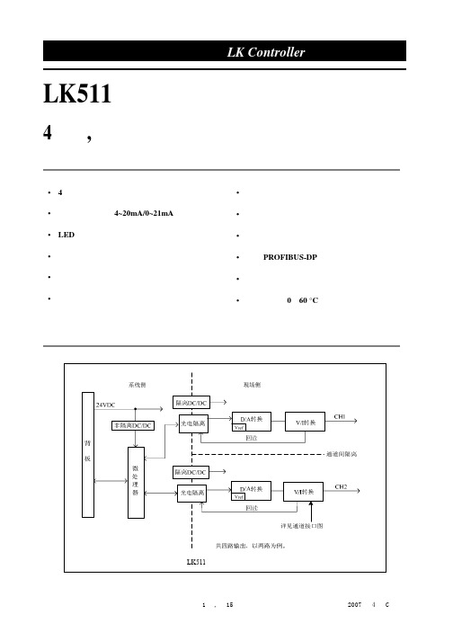
接线说明
LK511 模块电流输出接线图
注: 1. 4路电流型AO,仅使用图中4对接线端子,其余端子不用,严禁接线。 2. 每路信号分别用两根导线(屏蔽线缆)连接到现场设备上。
第 3 页,共 15 页
LK511 模块的接线端子固定在背板上,位于模块安装位的正下方。采用双排 18 位新型压力卡接端子, 相比较传统的螺钉端子,接线更加方便,更加牢固。
热备份冗余 DP 双网,高可靠性。符合 EN50170 欧洲标准,采用总线型网络拓朴结构,最大通讯速 率 1.5Mbps,通讯介质屏蔽双绞线。
LK511 模块支持 PROFIBUS-DP 从站协议,接收主站的输出数据并上传诊断信息。安装在本地背板 上,则从站地址由 LK511 模块所在槽位唯一确定;安装在扩展背板上,则从站地址由背板基地址和 LK511 模块所在槽位的偏移地址共同确定。
LK511 模块通过回读值对输出通道进行断线和输出故障的检测。CPU 把回读值与理论回读值进行比 较,诊断通道状态并上报诊断数据。
回读电流<4mA,则输出回路开路,通道断线,通道相关诊断区上报“断线故障”; 回读值与理论回读值之间误差>5%F.S.,则通道相关诊断区上报“通道输出故障”; 当通道所有故障均恢复时,通道相关诊断区上报“通道故障恢复”; 当通道上没有加负载时,视为通道断线,上报“断线故障”。 LK511 模块只在发生故障和故障恢复时分别上报一次诊断数据。针对不同的现场情况,出现故障时 模块的诊断处理方式也有所不同。
- 1、下载文档前请自行甄别文档内容的完整性,平台不提供额外的编辑、内容补充、找答案等附加服务。
- 2、"仅部分预览"的文档,不可在线预览部分如存在完整性等问题,可反馈申请退款(可完整预览的文档不适用该条件!)。
- 3、如文档侵犯您的权益,请联系客服反馈,我们会尽快为您处理(人工客服工作时间:9:00-18:30)。
调光模块内置丰富的通讯接口,可通过RS-232、RS-485或者ETHERNET等通讯接口实现与可编 程中央控制控制主机或者PC机通讯,可通过给调光模块设置不同的ID,同一通讯接口同时对多台调光 模块实现通信控制。
调光模块机身面板上提供了手动按键及LED状态指示灯,能通过机身的手动按键自由控制各路调 光,并由面板上LED指示灯指示当前通道工作状态。
四通道网络型调光模块
4通道网络调光模块
用 户 使 用 说 明 书
在使用产品前,请先详细阅读本使用手册
四通道网络型调光模块
模块——用户手册》只作为用户操作指示,不作为维修服务用途。 发行日期起,此后功能或相关参数若有变更,将另作补充说明,恕不另行通知, 详细可向各经销商查询。
本手册为产品生产商版权所有,未经许可,任何单位或个人不得将本手册之 部 分或其全部内容作为商业用途。
四通道网络型调光模块
! 安全操作指南
为确保设备可靠使用及人员的安全,在安装、使用和维护时,请遵守以下事项:
在设备安装时,应确保电源线中的地线接地良好,请勿使用两芯插头。确保设备的输入电 源的电压与主控机标注所需电压一致。
2
四通道网络型调光模块
二、结构与联接
2.1 前面板说明
○1 ○2 ○3
○1 、: 通道1~通道4 通道工作状态指示灯,通道打开时,对应指示灯亮,关闭通道,指示灯灭。 ○2 、LCD显示屏:调光模块工作状态显示及参数显示。 ○3 、Button按键:
非专业人士未经许可,请不要试图拆开设备部件,不要私自维修,以免发生意外事故或加 重设备的损坏程度。
不要将任何腐蚀性化学粉末或液体洒在设备上或其附近。
iii
四通道网络型调光模块
目录
一、功能介绍: ........................................................................................................................................................2 二、结构与联接 ........................................................................................................................................................3
机器内有交流220V 高压部件,安装、接线时请勿带电操作,以免发生触电危险。 请勿将设备置于过冷或过热的地方。
设备电源在工作时会发热,因此要保持工作环境的良好通风,以免温度过高而损坏机器。
阴雨潮湿天气或长时间不使用时,应关闭设备电源总闸。
在下列操作之前一定要将设备的输入交流电源线从交流供电电源处断开: A.取下或重装设备的任何部件。 B.断开或重接设备的任何电器插头或其它连接。
值。 3、多达 10 条调光曲线配置,支持多种种类的灯线性调光,在调节范围内亮度的改变完全一致,亮度
值控制采用百分比调光范围:0%(最暗)-100%(最亮),实际调光精度:13009 级(0-13009) 4、调光模块提供以下控制接口:
(1)提供 RS-232 IN、RS-232 OUT、RS-485、网络(同时支持 HTTP、TCP、UDP 工作方式) 接口,内嵌 Web 服务器,可通过 IE 等浏览器登录进行实时亮度调节及设备参数配置,多个设备可 进行 RS-232、RS-485 级联,最大可支持 999 台级联,可连接电脑和中控系统。 (2)提供 6 个按键配合面板液晶屏进行选项控制。 5、调光模块提供 4 个 LED 指示灯和 1 个 1602 字符液晶显示屏,4 个 LED 指示灯用于 4 个通道的状 态指示,指示灯的亮度会随着通道亮度调光值同步变化。 6、外接 8 个 IO 端口 8 个成对控制 4 个回路的亮度单独控制,IO 端口 1、2 控制通道一,IO 端口 3、4 控制通道二,IO 端口 5、6 控制通道三,IO 端口 7、8 控制通道四。前 IO 端口与 GND 脚短路,亮度持续增加,后 IO 端口与 GND 短路,亮度持续降低。 7、能够实现淡入淡出功能,淡入淡出时间可有 0 秒~~~255 秒可调 8、RS-232 和 RS-485 通讯时,提供通讯 LED 指示灯闪烁。 9、面板提供设备工作状态 LED 指示灯,快速确定设备的工作状态。 10、提供掉电记忆功能,来电后可恢复断电前状态,(通过上位机软件发送控制命令配置掉电记忆功 能,出厂默认为关闭,来电后采取渐变恢复的方式,平滑的把通道亮度值恢复到掉电前的状态) 11、支持改变串口通讯波特率,适应任何的波特率(300、600、900、1200、2400、4800、9600、 19200、38400、57600、115200 等)。 12、支持设备、通道、场景的备注命名及保存(支持中英文命名,提供 30 个英文字符及 15 个汉字字符 输入),可直观的显示设备、各通道、场景的实际连接备注,方便后期的维护。 13、提供 8 组场景的设置及调用。 14、提供跟机控制软件,可在 WINDOWS 各平台下运行。