PHANToM Haptic Interface and
FF中文介绍

触觉式三维设计系统公司简介•苏州文武系统工程有限公司是新型产业发展联盟的中小企业,在苏州工业园区行政中心附近。
全面的技术力量和专业的团队,为客户提供非接触式白光三维扫描仪、喷墨叠加式快速成型机、触觉式三维概念设计软件和三维检测、逆向工程、正向三维设计等相关处理软件及先进制造技术产品、技术支持和技术服务等一系列解决方案,主要用于计算机辅助检测、逆向工程、计算机辅助设计、快速原型和快速模具等,应用行业包括汽车制造、船舶制造、航空航天、模具制造、机械加工、制鞋、手机制造、牙科和整形、大学教育和科研等。
苏州文武系统工程有限公司是德国Breuckmann苏州办事处、美国3D SYSTEMS、美国SensAble、加拿大InnovMetric、美国SpaceClaim等公司在中国区的合作伙伴。
•我们提供的产品包括Breuckmann的白光扫描仪SmartSCAN、StereoSCAN、d-Station、b-Inspect、NaviSCAN和3D SYSTEMS喷墨叠加式快速成型机ProJet HD3000、ProJetSD3000、ProJet CP3000、ProJet CPX3000、ProJet5000、V-Flash以及SensAble概念设计系统FreeForm Modeling Plus、FreeForm Modeling,还有InnovMetric三维检测软件Polyworks、SpaceClaim无参化设计软件SpaceClaim2009等。
•公司理念:诚信、服从、执行、智慧、竞争•公司文化:互助是团队精神的核心•公司精神:合作、团结、耐力、执著、拼搏、和谐共生美国Sensable触觉式设计系统SensAble公司发展介绍SensAble Technologies 一个世界领导级的3D 触觉设计系统公司,源自于1990 年麻省理工学院(MIT)的研究项目,以“将触觉延伸到计算机内”为理念,致力于为制造业提供有效的设计方案,让设计者能与计算机直接互动。
面向磁悬浮视触觉交互的多速率系统框架

2021575触觉是人类赖以探索世界的重要感觉通道。
如今,提供实体触觉存在许多方式,如机械[1]、超声波[2]、喷气式[3]、磁悬浮[4]。
目前广泛使用的Geomagic Touch的Phantom[1]触觉设备基于机械传动方式提供触觉反馈,交互过程中受到机械关节固有摩擦、惯性的影响,且操作空间有限。
基于超声波[2]、喷气式[3]的非接触触觉反馈方式消除了机械交互方式中的固有摩擦,但仍存在些许不足,例如超声波触觉设备存在力传输距离较短、对噪声敏感、存在安全隐患等问题[2];喷气式设备由于采用空气作为力传导介质,力在压缩空气场中的传导速度较慢,且力反馈缺乏时空特性,操作空间有限[3]。
基于磁悬浮的非接触式触觉反馈消除了机械交互方式中的固有摩擦,且可通过自适应调节磁感线圈电流、摆放角度等方式,实现灵活的6-DOF触觉反馈[4],操作更加自由、稳面向磁悬浮视触觉交互的多速率系统框架石杰元1,袁志勇1,廖祥云2,赵俭辉11.武汉大学计算机学院,武汉4300722.中国科学院深圳先进技术研究院,广东深圳518055摘要:非接触式磁悬浮视触觉交互克服了机械式交互的固有摩擦,具有广阔应用前景,但存在交互过程中虚拟工具穿透物体、图形渲染与触觉渲染速率不一致等问题。
针对上述问题,提出面向磁悬浮视触觉交互的多速率系统框架,通过扩展三自由度(3-DOF)单射线触觉渲染方法,利用多射线对虚拟工具进行建模,避免工具穿透,实现六自由度(6-DOF)触觉渲染;通过多速率并行,实现速率不一致模块间相互协同;通过构建映射滤波算法,实现视觉定位数据到虚拟工具位姿的稳定映射。
实验结果表明,该系统能有效避免交互过程中的穿透现象,并提供稳定、真实的视触觉反馈。
关键词:视触觉交互;触觉渲染;磁悬浮;多速率并行文献标志码:A中图分类号:TP391.9doi:10.3778/j.issn.1002-8331.1912-0425Multirate Systematic Framework for Magnetic Levitation Visuo-Haptic InteractionSHI Jieyuan1,YUAN Zhiyong1,LIAO Xiangyun2,ZHAO Jianhui11.School of Computer,Wuhan University,Wuhan430072,China2.Shenzhen Institute of Advanced Technology,Chinese Academy of Sciences,Shenzhen,Guangdong518055,ChinaAbstract:Contactless magnetic levitation visuo-haptic interaction eliminates the inherent friction in the mechanical inter-actions and has promising prospects.However,there exist some problems in manipulating processes such as the unrealistic penetrations between the virtual tool and other virtual objects,the running velocity conflict between haptic rendering and graphical rendering.Aiming at these problems,a multirate systematic framework for magnetic levitation visuo-haptic interaction is proposed.By extending3-DOF ray-based haptic rendering methods,a6-DOF haptic rendering method is proposed which models the virtual tool using multiple rays avoiding penetrations.To handle the running velocity conflict, a multirate parallelization is performed.In addition,a mapping algorithm from the binocular positioning data to the posi-tions of virtual tool is proposed.Experimental results demonstrate that this system can prevent penetrations efficiently and produce stable and realistic visuo-haptic feedback.Key words:visuo-haptic interaction;haptic rendering;magnetic levitation;multirate parallelization基金项目:国家自然科学基金(61902386)。
克雷尔Phantom III立体扬声器预设置指南说明书
Phantom IIIStereo PreamplifierQUICK SETUP GUIDEGetting StartedThank you for your purchase of the Krell Phantom III Stereo Preamplifier . The Phantom III features Krell Current Mode circuit topologies, balanced technology, and a robust power supply for exceptional audio performance. The Phantom III preamplifier is the first Krell preamplifier to include an optional digital input module. It is also the first Krell preamplifier to include a headphone output. A thoughtful suite of menu options ensures that the Phantom III can be customized for the greatest ease of operation.The preamplifier’s front panel provides power, input selection, level control, menu functions, and status display. The rear panel allows connection to audio sources, power amplifiers, AC power, and other system components.The remote control provides power, preamplifier, level control, navigation and customization functions, CD and DVD player controls and menu configuration.Do not place the preamplifier where it could be exposed to dripping or splashing.Do not remove or bypass the ground pin on the end of the AC cord. This may cause radio fre-quency interference (RFI) to be introduced into your playback system.The ventilation slots on the top and bottom of the preamplifier must be unobstructed at all times during operation. Do not place flammable material on top of or beneath the component. Turn off all systems’ power before connecting the preamplifier to any component.Make sure all cable terminations are of the highest quality, free from frayed ends, short circuits, or cold solder joints.THERE ARE NO USER-SERVICEABLE PARTS INSIDE ANY KRELL PRODUCT1. Open the shipping box and remove the top layer of foam. Y ou will see theseitems:2. Carefully remove all items from the shipping box.3. Place the preamplifier in a safe location and remove the protective plastic wrap-ping.We recommend that you place the preamplifier on a firm, level surface, away from excessive heat, humidity, or moisture. The preamplifier requires at least two inches (5 cm) of clearance on each side and at least two inches (5 cm) of clearance above to provide adequate ventilation. Installations inside cabinetry may need extra venti-lation.The Phantom III preamplifier has superb regulation and does not require a dedi-cated AC circuit. Avoid connections through extension cords or multiple AC adapt-ers. High quality 15 amp AC strips are acceptable. The use of AC line conditioning devices is not recommended. The features provided by these devices are already on board the Phantom III.WARNINGSKrell Phantom III 1UnpackingKrell Industries, LLC., 45 Connair Road,Orange, CT 06477-3650 USA TEL203-298-4000,FAX203-891-2028,***************************WEB SITE Connecting the Phantom III to Y our SystemPosition the preamplifier where you intend to use it in your system.1. Neatly arrange and organize wiring to and from the preamplifier and all compo-nents. Separate the AC wires from any audio cables to prevent hum or other unwanted noise from being introduced into the system.2. Connect the outputs of your source equipment to the appropriate balanced(11), or single-ended inputs (12) on the Phantom III.3. Connect the main outputs (13) on the Phantom III to your amplifier’s inputs. 4. Connect the supplied AC power cord to the IEC power cord receptacle (17)of the preamplifier.5. Plug the other end of the AC power cord into AC power and turn on the rearpower switch. The display (3) shows PHANTOM III SOFTWARE VERSION , and the stand-by/power LED (4) illuminates red, indicating that the Phantom III is in stand-by mode. When the display shuts off, the Phantom III is ready to be pow-ered on.NoteUse only the power cord provided with the Phantom III to make the connection to AC power. Operation with a power cord other than the one supplied by Krell can induce noise, limit cur-rent, or otherwise impair the ability of the preamplifier to perform optimally.After the Phantom III is connected to your system and to AC power you may begin operation:1. Press the power button (1) on the front panel, or the remote control power key.The standby/power LED turns blue. The display shows the factory default input: S-1, and level: 000. The Phantom III is now in the operational mode.2. With the preamplifier output muted, or the volume fully attenuated, select asource manually using the front panel input select buttons (5 or 6) or the remote input select keys. Start playing the source. Use the level control knob (10) or the remote level keys to set the volume to a comfortable level.3. T o return the preamplifier to the stand-by mode, press the power button (1)or remote power key. (We recommend leaving the Phantom III in the stand-by mode when it is not playing music.)The balance function allows adjustment of the left and right balance. The options are: CENTER, L .5-5 dB <, R .5-5 dB >. The remote control has direct keys (D) to make these adjustments. For front panel adjustment follow the steps listed below.1. Press the preamplifier menu button (9), then use the level control knob, or theremote control up and down keys to select: BALANCE.2. Press the enter button (8) or remote enter key. The display shows the defaultmode: CENTER.3. Use the level control knob, or the up and down keys, to select the desired bal-ance option from 0 to +5 dB in .5 dB increments, left or right.4. Press the enter button or key to confirm the selection. The display reads:BALANCE.5. Press the menu button to exit the menu.4 Krell Phantom IIIOperating thePhantom III1 Preamplifier chassis1 IEC connector (AC power) cord 1 Remote control2 AAA remote batteries1 T -10 T orx wrench for remote 1 Quick Setup GuidePlacementAC POWER GUIDELINESSERIAL NUMBEROverviewChannel Balance AdjustmentKrell recommends using bal-anced interconnect cables. Balanced interconnect cables not only can minimize sonic loss but are also immune to induced noise, especially with installations using long cables. Balanced connections have 6 dB more gain than single-ended connections. When level matching is critical, keep this gain value in mind.NoteSave all packing materials. If you need to ship the Phantom III in the future, repack the unit in its original packaging to prevent shipping damage.This product complies with the EMC directive (89/336/EEC)and the low-voltage directive (73/23/EEC).This CLASS 1 apparatus must be connected to a MAINS socket outlet with a protective earthing connection.The owner's reference for this product, including a detaileddescription of features, technolo-gies, and warranty is available on the web at: MODEL Phantom III Preamplifier2 Krell Phantom IIIKrell Phantom III 3Figure 1 The Phantom III Front Panel Figure 2 The Phantom III Remote ControlFigure 3 The Phantom III Back PanelThis product is manufactured in the United States of America. Krell® is a registered trademark of Krell Industries, LLC., and is restricted for use by Krell Industries, LLC. its subsidiaries, and authorized agents. Krell Current Mode™ and Evolution CAST™ are trademarks of Krell Industries, LLC. All other trademarks and trade names are registered to their respective companies.© 2012 by Krell Industries, LLC., All rights reserved.Front Panel11 Balanced inputs: B-1 and B-2These XLR balanced analog source input connectors are wired as follows: Pin 1 GroundPin 2 Non-inverting Pin 3 Inverting 12 Single-ended inputs:S-1, S-2, and S-3 There are 3 single-ended analog source inputs with RCA con-nector pairs.13 Main outputsThe Phantom III is equipped with one bal-anced XLR output pair and one single-ended RCA output pair.Customizing thePhantom III1 PowerUse this to switch the preamplifier between stand-by and opera-tional modes.2 Display This provides channel status messages, in-cluding input selection, volume level, balance offset, and menu selec-tions.3 Infrared sensor This receives com-mands from the remote control. Make sure this is not obstructed.4 Stand-by/Power LED This preamplifier LED illuminates red (stand-by) when the Phantom III is plugged into a stan-dard AC wall receptacle and rear power switch is on. The LED illuminates blue (operational mode) when the power button (1) is pressed while the Phantom III is in stand-by mode.5 Analog Input selectors Use these to select the corresponding rear panel input that is connected to a single-ended (S-1, S-2, S-3), or balanced (B-1, B-2) ana-log source. The display (2) shows the selected input and volume level. Pressing the input but-ton on the active source will mute all outputs. A second press will unmute the outputs.6 Digital Input selec-tor (functional with optional D/A converter module)Use this to select the D/A converter module. Pressing and holding the digital button will cycle through the addi-tional digital inputs.7 Headphone Jack1/4" stereo headphone jack. The main outputs are muted when head-phones are being used.8 Enter buttonUse this to configure the menu functions of the Phantom III. See menu (9).Menu button Use this to access the menu functions of the Phantom III. For more information, see Customizing the Phantom III, in the owner’s reference.10 Level control knob Use this knob to increase or decrease system volume level. The level control knob or keys also select menu options that cus-tomize the Phantom III.14 RS-232 portThis port receives mes-sages from a computer-based control system, providing integrated control of all preamplifier functions. For details, see the developer's reference: RS-232 Port: Sending Commands and Interpreting Data.15 RC-5 inThis remote connector is used with third-party remote control systems that provide RC-5 (IR) data via a wired con-nection. A stereo tip, ring, sleeve 1/8” mini connector is used in the following configuration: Tip = RC-5 data Ring = +5 V Sleeve = GND.Configurable FunctionsAC MainsBalance (channel) Balance (input trim) Display, Info Input Level T rimInput Name, Input Phase Input T rigger , Mute,Output T rigger , Recall, Save, Theater .The menu button or key (9) allows you to configure functions. Enter the menu to view the list of configu-rable functions.Select a function to view a submenu of the list of options that configure the function. Y ou can configure some options as well, if a second submenu appears when you select an option.Navigation ConventionsNavigating the preamplifier menu is straightforward and consistent throughout, using 4 functions and the menu option BACK.9 Menu Button or Key T o enter the menu, press the menu button or key. Once you are in the menu, you can press the menu button or key to exit the menu.10 Level Control Knob or Up and Down Keys Use the level control knob or the up and down keys on the re-mote control to scroll forward and backward through the menu hier-archy. Each menu list is a continuous loop.For more information on menu configuration, review the Owner’s Reference on the Krell website at . Navigate to Downloads/ Current, then select the Phantom III from the product list. The publi-cation list for the Phantom III appears.8 Enter Button or Key Press this button or key to select a function or a configuration option, and confirm a selection 3 Front Panel Display The display shows the active function and con-figurable options.BACKSelect BACK to scroll backwards through the menu hierarchy, or to exit a menu option without confirming that option.16 12 VDC in/out (12 V trigger)There are 2 outputs and one input that send and receive 12 VDC power on/off (trigger) signals to and from other Krell components, and other devices that incor-porate a 12 V trigger. This allows other com-ponents to be turned on/off, or to/from stand-by, through the remote control.For more information, see Input Trigger in the owner’s reference.17 IEC power cordreceptacle and power switchThis is for use with the provided AC power cord. Plug the other end into an AC Mains supply capable of sup-plying the correct AC voltage and current for the power supply. This connector and power cord must remain unobstructed for easy removal in case of an emergency.18 Optional D/A Converter Module Location for future plug in D/A converter module.Keys labeled 1 to 10 have the same function (and callout number) as the front panel controls.Keys labeled A through K are unique to the re-mote control, and are described below:A Phase key Inverts the polarity of the audio signal. Alowercase i is displayed when the polarity is inverted.B Mute key Use this mute all out-puts. A second press of the mute key will unmute the outputs.C Sel(ect) keyCycles through the digi-tal inputs. This is only active when the optionalD/A converter module is installed.D Bal(ance) keysUse to balance left and right output levels.E Transport keys These keys are func-tional with all Krell CD and DVD players. F CD keyPress this to make the transport keys operate Krell CD players.G Direction keys Use these keys to navigate CD and DVD menus.H Select KeyUse this to make selec-tions from CD and DVD menus.I DVD keyPress this to make the transport keys operate DVD players. J Menu keyUse this to enter CD or DVD player menus.K Title key Use this with CD or DVD player menus.NoteThe remote is shipped with two AAA batteries that have to be instal-led. Use the supplied T orx wrench to remove the battery panel, then install the batteries.Remote ControlBack Panel。
Haptic Device
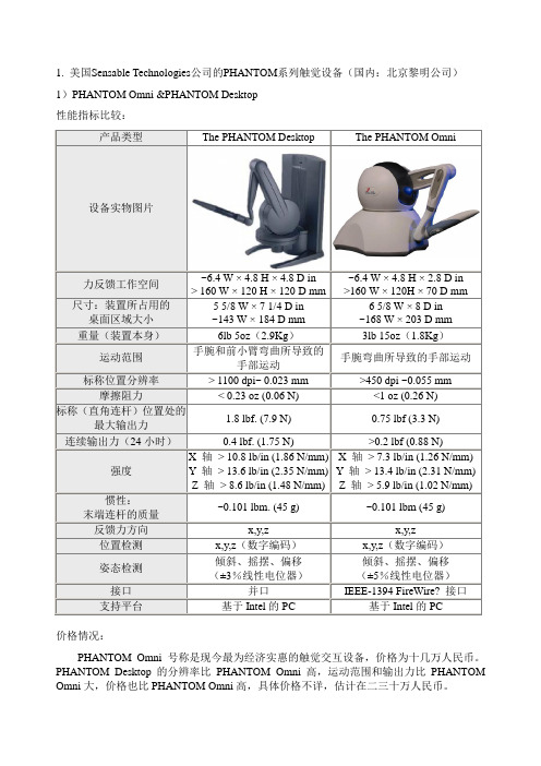
1. 美国Sensable Technologies 公司的PHANTOM 系列触觉设备(国内:北京黎明公司) 1)PHANTOM Omni &PHANTOM Desktop 性能指标比较:价格情况:PHANTOM Omni 号称是现今最为经济实惠的触觉交互设备,价格为十几万人民币。
PHANTOM Desktop 的分辨率比PHANTOM Omni 高,运动范围和输出力比PHANTOM Omni 大,价格也比PHANTOM Omni 高,具体价格不详,估计在二三十万人民币。
产品类型The PHANTOM Desktop The PHANTOM Omni设备实物图片力反馈工作空间 ~6.4 W × 4.8 H × 4.8 D in > 160 W × 120 H × 120 D mm~6.4 W × 4.8 H × 2.8 D in >160 W × 120H × 70 D mm尺寸:装置所占用的 桌面区域大小 5 5/8 W × 7 1/4 D in ~143 W × 184 D mm 6 5/8 W × 8 D in ~168 W × 203 D mm 重量(装置本身)6lb 5oz (2.9Kg )3lb 15oz (1.8Kg ) 运动范围手腕和前小臂弯曲所导致的手部运动手腕弯曲所导致的手部运动标称位置分辨率 > 1100 dpi~ 0.023 mm >450 dpi ~0.055 mm 摩擦阻力< 0.23 oz (0.06 N)<1 oz (0.26 N) 标称(直角连杆)位置处的最大输出力1.8 lbf. (7.9 N)0.75 lbf (3.3 N)连续输出力(24小时)0.4 lbf. (1.75 N) >0.2 lbf (0.88 N)强度 X 轴 > 10.8 lb/in (1.86 N/mm) Y 轴 > 13.6 lb/in (2.35 N/mm) Z 轴 > 8.6 lb/in (1.48 N/mm) X 轴 > 7.3 lb/in (1.26 N/mm) Y 轴 > 13.4 lb/in (2.31 N/mm) Z 轴 > 5.9 lb/in (1.02 N/mm)惯性: 末端连杆的质量 ~0.101 lbm. (45 g) ~0.101 lbm (45 g) 反馈力方向 x,y,zx,y,z位置检测 x,y,z (数字编码) x,y,z (数字编码) 姿态检测 倾斜、摇摆、偏移 (±3%线性电位器)倾斜、摇摆、偏移 (±5%线性电位器) 接口 并口IEEE-1394 FireWire? 接口支持平台基于Intel 的PC基于Intel 的PC2)PHANTOM Premium 1.0, 1.5, 1.5 High Force & 3.0性能指标比较:价格情况:PHANTOM Premium 1.0, 1.5, 1.5 High Force & 3.0系列触觉交互设备具有3 个自由度的力觉反馈,能检测3 个自由度的位置信息,还可以通过另外购买一支带有编码器的铁笔添加检测3 个自由度姿态信息的功能。
用于被动力觉再现的磁流变液制动器

用于被动力觉再现的磁流变液制动器朱静【摘要】为解决主动力觉驱动器的安全性、稳定性差等问题,研制了一种用于被动力觉再现的新型制动器.该制动器包括一个内置多个旋转盘的壳体,转子与壳体的间隙充满磁流变液.在磁场作用下当磁流变液粘度变大时,旋转盘相对于壳体将受制动力矩作用.建立了制动器的动力学模型,分析了制动器输出力的约束条件,通过研究转子转速反馈算法和输出力矩反馈算法建立制动器的简化逆动力学模型.虚拟力觉再现实验结果显示:制动器输出力的动态变化系数大于20,能够高保真地实现肌体组织的柔顺性再现和硬物的刚性再现.%In view of the poor safety and poor stability of current haptic actuators, a novel brake is developed for passive force display. It consists of a housing with several rotors located in it. The magneto-rheological fluid is filled into the gaps between the rotors and the housing. When the viscosity of the magneto-rheological fluid increases under the influence of the magnetic field, the rotors are resisted by the braking torque relative to the housing. The dynamic model of the brake is built. The constrain conditions of the brake output force are analyzed. A simplified inverse dynamic model of the brake is built by studying the speed feedback algorithm of the rotors and the output torque feedback algorithm. Virtual force display experiment results show that the brake output force can realize the compliance display of body tissues and the rigidity display of rigid bodies with high fidelity, and its dynamic change coefficients are above 20.【期刊名称】《南京理工大学学报(自然科学版)》【年(卷),期】2011(035)006【总页数】5页(P817-821)【关键词】被动力觉再现;磁流变液;制动器;简化逆动力学模型【作者】朱静【作者单位】江苏省电子产品装备制造工程技术研究开发中心,江苏淮安223003【正文语种】中文【中图分类】TP24对人类获取信息能力的研究表明,视觉信息所占的比例最大,但是当机器人与环境相互作用时,比如组装工件、插销入孔等,仅仅依靠视觉信息,操作者不能从中获得真实的力感受。
Sensable PHANTOM Omni 力反馈--说明书(中文版)
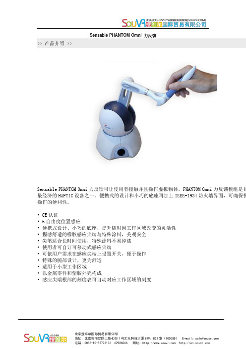
Sensable PHANTOM Omni 力反馈
>> 产品介绍 >>
Sensable PHANTOM Omni力反馈可让使用者接触并且操作虚拟物体。
PHANTOM Omni力反馈模组是目最经济的HAPTIC设备之一。
便携式的设计和小巧的底座再加上IEEE-1934防火墙界面,可确保快操作的便利性。
• CE认证
• 6自由度位置感应
•便携式设计、小巧的底座,提升随时因工作区域改变的灵活性
•握感舒适的橡胶感应尖端与特殊涂料,美观安全
•尖笔适合长时间使用,特殊涂料不易掉漆
•使用者可自订可移动式感应尖端
•可依用户需求在感应尖端上设置开关,便于操作
•特殊的腕部设计,更为舒适
•适用于小型工作区域
•以金属零件和塑胶外壳构成
•感应尖端根部的刻度表可自动对应工作区域的刻度
应用范围
适用于虚拟会议、虚拟模型、维持路径规划、多媒体和分子模型化等众多应用领域。
VR眼镜的英语作文
Virtual Reality VR headsets have revolutionized the way we experience digital content,offering an immersive experience that transports users into a completely different world.Heres an English essay on VR glasses that delves into their features, applications,and potential impact on various industries.Title:The Marvel of Virtual Reality GlassesIntroduction:In the realm of technology,Virtual Reality VR glasses have emerged as a groundbreaking innovation,offering users a chance to step into alternate realities.These devices have transformed gaming,education,and even healthcare,providing a multisensory experience that was once the stuff of science fiction.Development and Technology:The development of VR glasses has been a journey of technological advancements.Early models were bulky and limited in functionality,but modern VR headsets are sleek, comfortable,and packed with features.They utilize highresolution displays,wide fieldofview lenses,and sophisticated motion tracking to create a convincing virtual environment.The integration of spatial audio and haptic feedback further enhances the realism of the experience.Applications in Gaming:Gaming has been at the forefront of VR adoption.VR glasses have taken gaming to new heights,allowing players to physically move and interact within game worlds.This has led to the creation of entirely new genres of games that rely on the immersive nature of VR,such as virtual reality escape rooms and interactive storytelling experiences. Education and Training:In the field of education,VR glasses are transforming the way students learn.They provide a platform for virtual field trips,allowing students to explore historical sites, outer space,or the human body in a way that textbooks and traditional classrooms cannot match.Moreover,VR is used for training in various professional fields,including medical,military,and aviation,where realistic simulations are crucial for skill development.Healthcare and Therapy:VR glasses have found a niche in healthcare,particularly in therapy and rehabilitation. They are used to treat phobias,anxiety disorders,and posttraumatic stress disorder through exposure therapy in a controlled environment.Additionally,VR is employed in physical therapy to motivate patients with engaging exercises that can be tailored to theirspecific needs.Design and User Experience:The design of VR glasses is crucial for a comfortable and enjoyable user experience. Modern headsets are lightweight and ergonomic,with adjustable straps and padding to fit a variety of head shapes and sizes.The user interface is intuitive,allowing users to navigate through menus and options with ease,often using hand controllers or gesture recognition.Challenges and Future Prospects:Despite their many benefits,VR glasses face challenges such as high costs,motion sickness,and the need for powerful computing hardware.However,ongoing research and development are addressing these issues,with the aim of making VR more accessible and comfortable for a wider audience.The future of VR glasses looks promising,with advancements in wireless technology,eyetracking,and even braincomputer interfaces on the horizon.Conclusion:Virtual Reality glasses are not just a novelty they are a testament to human ingenuity and the relentless pursuit of immersive digital experiences.As technology continues to evolve, the applications of VR glasses will undoubtedly expand,offering new opportunities for exploration,learning,and healing in ways we are only beginning to imagine.。
虚拟装配——精选推荐
虚拟装配1定义和分类1.1虚拟装配的定义虚拟装配一般定义为:无需产品或支撑过程的物理实现,只需通过分析、先验模型、可视化和数据表达等手段,利用计算机工具来安排或辅助与装配有关的工程决策。
虚拟装配是一种将CAD 技术、可视化技术、仿真技术、决策理论及装配和制造过程研究、虚拟现实技术等多种技术加以综合运用的技术。
虚拟装配是虚拟制造的重要组成部分,利用虚拟装配,可以验证装配设计和操作的正确与否,以便及早的发现装配中的问题,对模型进行修改,并通过可视化显示装配过程。
虚拟装配系统允许设计人员考虑可行的装配序列,自动生成装配规划,它包括数值计算、装配工艺规划、工作面布局、装配操作所模拟等。
现在产品的制造正在向着自动化、数字化的反向发展,虚拟装配是产品数字化定义中的一个重要环节。
虚拟装配技术的发展是虚拟制造技术的一个关键部分,但相对于虚拟制造的其它部分而言,它又是最薄弱的环节。
虚拟装配技术发展滞后,使得虚拟制造技术的应用性大大减弱,因此对虚拟装配技术的发展也就成为目前虚拟制造技术领域内研究的主要对象,这一问题的解决将使虚拟制造技术形成一个完善的理论体系,使生产真正在高效、高质量、短时间、低成本的环境下完成,同时又具备了良好的服务。
虚拟装配从模型重新定位、分析方面来讲,它是一种零件模型按约束关系进行重新定位的过程,是有效的分析产品设计合理性的一种手段;从产品装配过程来讲,它是根据产品设计的形状特性、精度特性,真实的模拟产品三维装配过程,并允许用户以交互方式控制产品的三维真实模拟装配过程,以检验产品的可装配性。
1.2虚拟装配的分类根据虚拟装配过程中出现的不同侧重点,可以将虚拟装配归纳成三种主要的类别。
(1)以设计为中心的虚拟装配以设计为中心的虚拟装配是指在产品三维数字化定义应用于产品研制过程中,结合产品研制的具体情况,突出以设计为核心的应用思想,这表现在以下三个方面:1)面向装配设计:在设计初期把产品设计过程与制造装配过程有机结合,从设计的角度来保证产品的可装配性。
FreeForm软件教程-V10新增功能详解
三、V10 加强功能如下: Curvers:
1、 Draw curve 画 3D 曲线
Trace while button is pressed:不勾选时,曲线终点手动按 End 结束; 勾选时,按住按钮画线,直到松开按钮时曲线自动终止。 2、按住Shitf可延着最近的轴向画线(即画水平线或垂直线)。
详细功能说明请参考
此指令)。
3、
Tug with Curve 依曲线变形“参考粘土”
半径
变形区域侧面的形状
高品质 微调 锁定轴向 取消 执行
Patches/Solids:
1、
Edit and Stitch Solid 编辑实体并缝合
注:(此指令的详细功能请参考
Edit and Stitch Reference Piece)
二、新增指令功能详细说明:
第 2 页,共 20 页
广东博泰科技有限公司
FreeForm 功能中文说明
Sketch:
1、
Extend/Retract Sketch Curve 延伸 2D 曲线
曲线的延伸方式
延长现有的曲线 延长的部分成另一条曲线
曲线长度
细部说明:
Tangent Reflection Curvature Tangent(to point)
Mode 延伸方式
曲线端点由切线 tangent(G1)方式延伸 曲线端点由曲率 curvature(G2)方式延伸,延长的曲线将自动增加 控制点(不影响原有的控制点数量,自动新增控制点) 曲线端点由曲率 curvature(G2)方式延伸,延长的曲线控制点不新 增(原有的控制点重新排列,不增加数量) 曲线端点由切线 tangent(G1)方式延伸,延伸部分曲线终点位置可 任意设定
模块化机器人设计
模块化机器人设计摘要如今,机器人的发展突飞猛进,机器人服务已经覆盖了人们生活、工作、娱乐的方方方面。
随着人类的需求的不断增加,对机器人领域的探索也越走越远,机器人模块化技术已在各个领域的产品研究和开发中广泛应用。
于传统机器人相对比,模块化机器人柔性更好,自修复能力强柔性高,且容错性强、成本较低。
模块化结构较简单,便于加工,各模块能互相替换,组装快捷简便。
由于模块化机器人结构和功能的可重组性,对任务和环境有很强的适应能力。
采用模块化技术,有利于机器人的维护和保养,缩短了机器人设计的时间。
因此,本文将采用模块化的方法开发一种新机器人系统,希望有利于改善目前机器人控制复杂、通用性差和操作繁琐等问题。
本文一共分为六个部分,第一部分绪论主要概括模块化机器人的研究背景、意义和国内外模块化机器人研究现状,第二部分探讨了机器人模块化的设计原理和方法,第三部分主要讨论了机器人控制系统设计,第四部分分析机器人主从控制策略。
第五部分概述了机器人构型,最后进行了小结。
关键词:机器人;模块化;系统设计;构型Nowadays, the development of robots is advancing by leaps and bounds. Robot service has covered all aspects of people's life, work and entertainment. With the increasing demand of human beings, the exploration of robot field is more and more far away. Robot modularization technology has been widely used in product research and development in various fields. Compared with the traditional robot, modular robot is more flexible, self repairing ability, high flexibility, and good fault tolerance and low cost. The modular structure is simple, easy to process, each module can replace each other, and the assembly is quick and easy. Because of the reconfiguration of modular robot structure and function, it has a strong adaptability to task and environment. Modular technology is beneficial to the maintenance and maintenance of robots, and shortens the time of robot design. Therefore, this paper will use modular method to develop a new robot system, in the hope of improving the complexity of robot control, low universality and tedious operation. This paper is divided into six parts, the first part is the introduction mainly summarizes the modular robot research background, significance and research status quo of inside and outside of the modular robot, the second part discusses the design principle and method of modular robot, the third part mainly discusses the design of robot control system, the fourth part of the analysis of the master-slave robot control strategy. In the fifth part, the configuration of robot is summarized, and finally a brief summary is made.Key words: robot; modularization; system design; configuration摘要 (1)Abstract (2)第一章绪论 (4)1.1研究背景及意义 (4)1.2国内外研究现状 (4)第二章机器人模块化设计原理及设计方法 (5)2.1模块的划分 (5)2.1.1模块化思想概述 (5)2.1.2模块划分原理 (6)2.2模块化设计方法 (6)2.3随遇平衡的实现 (6)2.3主机器人模块 (8)2.3.1 I模块 (8)2.3.2 T模块 (9)2.3.3 应用模块化方法的效果 (10)3.1控制系统硬件设计 (10)3.2单片机最小系统模块 (11)3.3 CAN通信模块设计 (11)3.4控制器设计 (12)第四章机器人主从控制策略 (12)4.1从机器人系统搭建 (12)4.2同构型主从控制策略 (13)4.3镜像同构型主从控制策略 (14)第五章机器人构型 (16)第六章结论 (18)参考文献 (19)第一章绪论1.1研究背景及意义机器人结构不同,通用性也不一样。
- 1、下载文档前请自行甄别文档内容的完整性,平台不提供额外的编辑、内容补充、找答案等附加服务。
- 2、"仅部分预览"的文档,不可在线预览部分如存在完整性等问题,可反馈申请退款(可完整预览的文档不适用该条件!)。
- 3、如文档侵犯您的权益,请联系客服反馈,我们会尽快为您处理(人工客服工作时间:9:00-18:30)。
The MIT Press Journals/journalsThis article is provided courtesy of The MIT Press.To join an e-mail alert list and receive the latest news on our publications, please visit: /e-mailMurat Cenk C¸avus¸og˘lu cavusoglu@ Department of Electrical Engineering and Computer Science Case Western Reserve University Cleveland,OH44106David Feyginfeygin@ Department of Mechanical EngineeringUniversity of California Berkeley,CA94720Frank Tendicktendick@ Department of Surgery University of CaliforniaSan Francisco,CA94143Presence,Vol.11,No.6,December2002,555–568©2002by the Massachusetts Institute of Technology A Critical Study of the Mechanical and Electrical Properties of the PHANToM Haptic Interface and Improvements for High-Performance ControlAbstractThis paper presents a critical study of the mechanical and electrical properties of the PHANToM haptic interface and improvements to overcome its limitations for applications requiring high-performance control.Target applications share the com-mon requirements of low-noise/granularity/latency measurements,an accurate sys-tem model,high bandwidth,the need for an open architecture,and the ability to operate for long periods without interruption while exerting significant forces.To satisfy these requirements,the kinematics,dynamics,high-frequency dynamic re-sponse,and velocity estimation of the PHANToM system are studied.Furthermore, this paper presents the details of how the unknown subsystems of the stock PHANToM can be replaced with known,high-performance systems and how addi-tional measurement electronics can be interfaced to compensate for some of the PHANToM’s shortcomings.With these modifications,it is possible to increase the maximum achievable virtual wall stiffness by35%,active viscous damping by120%, and teleoperation loop gain by50%over the original system.With the modified system,it is also possible to maintain higher forces for longer periods without caus-ing motor overheating.1IntroductionThe PHANToM force-reflecting haptic interface,which was originally designed by Massie and Salisbury(1994)and subsequently commercialized by SensAble Technologies,Inc.,is widely used in the haptics community in a multitude of applications due to its large workspace,low inertia,low friction, and high position-precision characteristics.Although this system has been used successfully as a haptic interface in typical virtual environment(VE)and telero-botics applications,the performance characteristics of the stock PHANToM do not meet the requirements of some high-performance applications.In this paper,we present a critical study of the mechanical and electrical properties of the PHANToM haptic interface and improvements to overcome its limitations for applications requiring high-performance control.This work is motivated by our research group’s experience using the PHANToM system in high-performance tasks in the areas of medical robotics and VE-based surgi-cal training simulators.The main applications includeC¸avus¸og˘lu et al.555●implementation of complex control algorithms thatrequire accurate measurements of position andvelocity,as well as dynamic models of themanipulator,●design of bilateral teleoperation control algorithmsfor high-fidelity telemanipulation of soft objects(Sherman,C¸avus¸og˘lu,&Tendick,2000;C¸avus¸o-g˘lu,Sherman,&Tendick,2002),●high-fidelity haptic interaction with deformable ob-jects in virtual environments(C¸avus¸og˘lu&Ten-dick,2000),●haptic guidance for training(Feygin,Keehner,&Tendick,2002),and●psychophysics experiments to determine frequency-dependent force and impedance sensitivity of hu-man subjects(Dhruv&Tendick,2000)Although our range of applications is very broad,the applications sharefive fundamental requirements.These are as follows.●Need for open architecture:Because the electricaland software subsystems of the PHANToM haptic interface come as a black box,full functionality orcontrol of the system is not allowed.Furthermore, the black box structure conceals the inner workings of the system,which may effect experimental re-sults.This is not desirable for basic research.Forexample,one application is the experimental com-parison of different teleoperation control algo-rithms;in this case,having a black box does notallow for a fair comparison or generalizable results.This is also true for psychophysics experiments be-cause the unknown behavior of the system maycolor the experimental results.●Low-noise/granularity/latency measurements:Whenattempting to implement high-performance control algorithms or provide accurate haptic feedback,it is important to have sensors that provide accurate and timely information on the state of the system be-cause the controller uses this information to deter-mine the appropriate control action.When the in-formation is not accurate or has a large latency,the performance of the controlled system suffers.●Accurate system model:When implementing controlalgorithms,it is desirable to have a model of thesystem.The more accurate this model is,the greater the performance that can be achieved.●High bandwidth:High-fidelity telerobotics applica-tions,such as telemanipulation of soft tissue inmedical applications,require a relatively high-bandwidth closed-loop response.This is becausethe force and stiffness sensitivity of the human oper-ator increases with frequency(Dhruv&Tendick,2000).●Long operating periods without interruption whileexerting significant forces:For psychophysics experi-ments,it is necessary to apply significant forces forlong periods.It is important not to interrupt theexperiments because of motor overheating.To satisfy these requirements,the PHANToM’s kine-matics,dynamics,high-frequency dynamic response, and velocity estimation are analyzed.Furthermore,we describe how we replaced the unknown subsystems of the stock PHANToM with known,high-performance systems and interfaced additional measurement elec-tronics to compensate for some of the PHANToM’s shortcomings.At this point,we would like to emphasize that our target applications require relatively high performance, and we do not want to imply that the PHANToM is not adequate for most virtual reality applications.On the contrary,the system works without noticeable prob-lems until one tries to push it to the limits of its perfor-mance envelope.In this paper,wefirst derive the forward and inverse kinematics and the dynamic equations of motion assum-ing infinitely stiff joints and zero friction.We then dis-cuss various limitations to the high-performance control of the PHANToM and modifications that were imple-mented to overcome these limitations.We then develop a theoretical and experimental transfer function model of the PHANToM hardware.Finally,we experimentally evaluate the modifications in a number of applications and discuss the generalizability of these results to other PHANToM models.556PRESENCE:VOLUME11,NUMBER6In this document,we will follow the notation ofMurray,Li,and Sastry (1994)in representing rigid-body transformations and kinematics and dynamics cal-culations.Results of the calculations are also related to the notation of Craig (1989).The units are in meter-kilogram-second (MKS),unless otherwise noted.Throughout the paper,parameters and measurements are based on the PHANToM model 1.5.2KinematicsIn this section,the kinematic analysis of thePHANToM manipulator is performed.Although some of the results given here are already implemented in SensAble ’s GHOST and Basic I/O libraries,we believe it is useful to have explicit expressions for the sake of having an open architecture and to use in tasks and functions not supported in these libraries.In the following subsections,solutions of the forward and inverse kinematics are presented,followed by the calculation of the manipulator Jacobian and a basic anal-ysis of the workspace.2.1Forward KinematicsUsing the zero con figuration and the naming con-vention shown in figure 1,the kinematic con figurationof the manipulator is characterized by the following vec-tors and points:w 1ϭ͓010͔Tw 2ϭw 3ϭ͓Ϫ100͔Tq 1ϭ͓00Ϫl 1͔Tq 2ϭq 3ϭ͓0l 2Ϫl 1͔Ti ϭͫϪw iϫq i w iͬ,i ϭ1,2,3.Values for l 1and l 2for the PHANToM model 1.5are given in the appendix.It can easily be seen from the side and top view illus-trations in figure 2that the forward kinematic map is givenbyFigure 1.Zero configuration of themanipulator.Figure 2.Side and top views.C ¸avus ¸og ˘lu et al.557g st ͑͒ϭͫR()p()000ͬwhereR ͑͒ϭe wˆ11e wˆ33I 3ϫ3(1)andp ͑͒ϭe ˆ11e ˆ22΄I 3ϫ3l 20001΅΄0001΅ϩ΄R ͑͒ͫ0Ϫl 20ͬ0΅.In closed form,g st ͑͒ϭ΄cos ͑1͒Ϫsin ͑1͒sin ͑3͒cos ͑3͒sin ͑1͒sin ͑1͒͑l 1cos ͑2͒ϩl 2sin ͑3͒͒0cos ͑3͒sin ͑3͒l 2Ϫl 2cos ͑3͒ϩl 1sin ͑2͒Ϫsin ͑1͒Ϫcos ͑1͒sin ͑3͒cos ͑1͒cos ͑3͒Ϫl 1ϩcos ͑1͒͑l 1cos ͑2͒ϩl 2sin ͑3͒͒0001΅In the notation of Craig (1989),T ST ϭg st ()above.2.2Inverse KinematicsAs this is a three-DOF manipulator,the inverse kinematics problem is to find the set of (1,2,3)tri-ples that moves the manipulator to a desired end effec-tor position p o ϭ͓p ox p oy p oz ͔T .(1is determined by inspection from the top view in figure 2,and 2and 3are determined again by inspection and using law of cosines twice on the side view.)The resulting angles are given by1ϭatan2͑p ox ,p oz ϩl 1͒d ϭͱox 2ϩ(p oz ϩl 12r ϭͱp ox 2ϩ͑p oy Ϫl 2͒ϩ͑p oz ϩl 1͒2ϭcosϪ1ͩl 12ϩr 2Ϫl 221ͪϩatan2͑p oy Ϫl 2,d ͒3ϭ2ϩcosϪ1ͩl 12ϩl 22Ϫr 22l 1l 2ͪϪ2,where d and r are intermediate variables.2.3Manipulator JacobianThe body Jacobian of the manipulator is given byJ b ͑͒ϭͫ···ͩgstϪ1␦g st␦iͪv···ͬϭ΄l 1cos ͑2͒ϩl 2sin ͑3͒00l 1cos ͑2Ϫ3͒00Ϫl 1sin ͑2Ϫ3͒l 200Ϫ1cos ͑3͒00sin ͑3͒00΅Using the body Jacobian of the manipulator,the hybridvelocity of the tool frame (the translational and angular velocity of the tool frame,around the origin of the tool frame,expressed in spatial coordinates)is calculated asV h ϭͫR 00R ͬJ b˙,where R is given in equation seven.In the notation ofCraig (1989),S V ϭV h .The motor torques required to counteract the hybrid wrench F h applied to the manipu-lator are given byϭJb TͫR T 00R T ͬF h .558PRESENCE:VOLUME 11,NUMBER 6The hybrid wrench is the force/torque combination applied to the origin of the tool frame expressed in spatial coordinates.In the notation of Craig (1989),SF ϭF h .Figure 3shows the workspace and the manipulability of the PHANToM.The manipulability measure usedhere is ϭmin (J u b )/max (J u b),where min and max are the minimum and maximum singular values,and J u b is the upper half of the manipulator Jacobian (which cor-responds to the translational part).This plot reveals that the PHANToM haptic interface has a singularity-free workspace with quite uniform manipulability over a sig-ni ficant portion of the workspace,which is a favorable kinematic property.3DynamicsIt is necessary to know the dynamic equations ofmotion for the manipulator to implement high-perfor-mance controllers such as gravity compensation or the computed torque control algorithm.The dynamic equa-tions for the PHANToM manipulator are in the form΄M 11000M 22M 230M 32M 33΅΄¨1¨2¨3΅ϩ΄C 11C 12C 13C 210C 23C 31C 320΅΄˙1˙2˙3΅ϩ΄0N 2N 3΅ϭ΄123΅where M 11ϭ18ͩ4I ayy ϩ4I azz ϩ8I baseyy ϩ4I beyy ϩ4I bezz ϩ4I cyy ϩ4I czz ϩ4I df yy ϩ4I df zz ϩ4l 12m a ϩl 22m a ϩl 12m c ϩ4l 32m cͪϩ1ͩ4I beyyϪ4I bezz ϩ4I cyy Ϫ4I czz ϩl 12͑4m a ϩm c ͒ͪcos ͑22͒ϩ18ͩ4I ayy Ϫ4I azz ϩ4I df yy Ϫ4I df zzϪl 22m a Ϫ4l 32m c ͪcos ͑23͒ϩl 1͑l 2m a ϩl 3m c ͒cos ͑2͒sin ͑3͒M 22ϭ14͑4͑I bexx ϩI cxx ϩl 12m a ͒ϩl 12m c ͒M 23ϭϪ12l 1͑l 2m a ϩl 3m c ͒sin ͑2Ϫ3͒M 32ϭϪ1l 1͑l 2m a ϩl 3m c ͒sin ͑2Ϫ3͒M 33ϭ14͑4I axx ϩ4I df xx ϩl 22m a ϩ4l 32m c ͒C 11ϭ18ͩϪ2sin ͑2͒ͩ͑4I be yy Ϫ4I be zz ϩ4I cyy Ϫ4I czz ϩ4l 12m a ϩl 12m c ͒cos ͑2͒ϩ2l 1͑l 2m a ϩl 3m c ͒sin ͑3͒ͪ˙2ϩ2cos ͑3͒ͩ2l 1͑l 2m a ϩl 3m c ͒cos ͑2͒ϩ͑Ϫ4I ayy ϩ4I azz Ϫ4I df yy ϩ4I df zz ϩl 22m a ϩ4l 32m c ͒sin ͑3͒ͪ˙3ͪFigure 3.Workspace and manipulability.This plot shows the crosssection of the workspace and isomanipulability curves of thePHANToM at the x ϭ0plane,which corresponds to 1ϭ0.Note that the kinematics are circularly symmetric for 1.C ¸avus ¸og ˘lu et al.559C 12ϭϪ18ͩ͑4I beyy Ϫ4I bezz ϩ4I cyy Ϫ4I czz ϩl 12͑4m aϩm c ͒͒sin ͑22͒ϩ4l 1͑l 2m a ϩl 3m c ͒sin ͑2͒sin ͑3͒ͪ˙1C 13ϭϪ18(Ϫ4l 1͑l 2m a ϩl 3m c ͒cos ͑2͒cos ͑3͒Ϫ(Ϫ4I ayyϩ4I azz Ϫ4I df yy ϩ4I df zz ϩl 22m a ϩ4l 32m c )sin ͑23͒)˙1C 21ϭϪC 12C 23ϭ12l 1͑l 2m a ϩl 3m c ͒cos ͑2Ϫ3͒˙3C 31ϭϪC 13C 32ϭ12l 1͑l 2m a ϩl 3m c ͒cos ͑2Ϫ3͒˙2N 2ϭ1g ͑2l 1m a ϩ2l 5m bc ϩl 1m c ͒cos ͑2͒N 3ϭ1g ͑l 2m a ϩ2l 3m c Ϫ2l 6m df ͒sin ͑3͒.These dynamic equations assume that the gravity vec-tor is in the Ϫy direction.The estimated numerical val-ues for the inertial parameters for the PHANToMmodel 1.5manipulator are given in appendix A.Details of the derivation of the dynamic equations and inertial parameters can be found in C ¸avus ¸og ˘lu and Feygin (2001).4Control IssuesWhen pushing the PHANToM to the edge of its performance envelope,one encounters a number of lim-itations that impede high-performance control.In this section,some of the factors limiting the performance of the stock PHANToM system are described,and im-provements that mitigate these limitations are pre-sented.Furthermore,an accurate frequency response and system model is presented for the purpose of high-performance control.4.1Limitations of the PHANToM Initial attempts at high-bandwidth position con-trol during bilateral teleoperation with two PHANToMmanipulators,using a simple PD controller,resulted ininstability even at moderate gains.Furthermore,a reso-nance was observed at 125Hz.The inadequate perfor-mance of the stock PHANToM during these initial at-tempts prompted further investigation of the PHANToM system.4.1.1Motor drive electronics.The motor drive electronics come as a black box for which the system behavior is not known.This con flicts with our need for an open architecture.It is not desirable to drive DC brush motors withvoltage-regulating ampli fiers on haptic devices for which one wants to servo forces.First,for DC motors,torque is proportional to current,not voltage.Second,brush DC motors (as the name implies)contain brushes,and,when these brushes switch,the resistance of the wind-ings changes.If the ampli fier regulates voltage,the change in resistance causes a change in the current,and thus a change in the motor torque.This is called cog-ging,and it contaminates the haptic feedback.With the original PHANToM ampli fier box,one can feel a spa-tially periodic variation in force during a constant-force command.This may be attributable to motor cogging.The ampli fier box supplied with the PHANToM sys-tem uses a motor drive based on pulse width modula-tion (PWM).Although PWM is adequate in many ap-plications,the high-frequency switching associated with the PWM signal makes it inadequate for high-perfor-mance applications.The PWM signal has signi ficant power in the high-frequency range due to the switching and is therefore more likely to excite high-frequency dynamics that could lead to instability as compared to a linear signal.The PWM power drive also increases motor overheat-ing as compared to a linear drive.When conducting psy-chophysics experiments with the stock PHANToM setup,we noticed that the application of reasonable fin-ger forces for prolonged periods with little motion caused a fault in the software due to the overheating of the motors.This problem is signi ficantly mitigated by using linear current ampli fiers.The heat dissipation in a motor is given by I 2R,where I is the motor current and R is the resistance of the motor windings.The ratio of560PRESENCE:VOLUME 11,NUMBER 6heat dissipation with the PWM amplifiers over the linear current amplifiers isI max2ϫDuty CycleϫR͑I maxϫDuty Cycle͒2ϫRϭ1 Duty Cycle.For example,at one fourth of full force,or25%duty cycle,the original PWM amplifier results in four times the heat dissipation of a linear amplifier.4.1.2Velocity estimation.The PHANToM hasa position precision of0.03mm at the center of the workspace(SensAble Technologies,1997),but the granularity of velocity measurements at the haptic sam-pling rate of1kHz is⌬vϭ(⌬x/⌬t)ϭ(0.03mm/0.001sec)ϭ30mm/sec.Although the position preci-sion is good,this level of velocity granularity is very large,especially for a haptic interface,which will typi-cally move at low velocities.The PHANToM Basic I/O libraries use a velocity estimate averaged over100sam-ples,which results in an approximate lag of50ms (SensAble Technologies,Inc.1997).This much lag can induce instability at moderate velocity gains in the con-trol loop(50ms of lag adds180deg.of phase at10 Hz).The mechanical system of the PHANToM has mini-mal damping.Therefore,it is important to have active damping with velocity feedback to stabilize the system. However,the large velocity granularity and the lag in-troduced from the averaging does not allow effective velocity feedback.Furthermore,many virtual environ-ment and haptic training applications require large amounts of damping.4.2System improvementsThe following improvements have been made to the PHANToM system to overcome the limitations de-scribed in the previous section and achieve improved performance.4.2.1Motor drive electronics.To overcome the limitations associated with the original PHANToM motor drive electronics(as well as to replace the black box component with a known component),the original amplifier box is replaced with a high-performance,linear current amplifier(from Glentek,El Segundo,CA,part number GA4555).This amplifier provided more than adequate continuous power/linearity and bandwidth for high-performance control of the PHANToM.It is im-portant to note that,when the PHANToM amplifier box is not used,the update rate and temperature con-trol safety logic are bypassed as well.It is therefore im-portant to implement these in the drivers for the new amplifiers.4.2.2Velocity estimation.A period measure-ment velocity estimation system,following the method proposed by Lemkin,Yang,Huang,Jones,and Aus-lander(1995),was developed and interfaced with the PHANToM electronics to mitigate the problem of large velocity granularity.This velocity estimation system measures the period between encoder counts.A Lattice 3320FPGA was programmed to decode the quadrature signal to determine direction,count the number of clock ticks between pulses,and communicate to the computer through16bits of digital I/O.Running a10 MHz clock with a16-bit counter allowed more than adequate dynamic range for measurements of both small and large end effector velocities,with very little granu-larity.However,at low velocities,the update rate is re-duced below the nominal1kHz because no new infor-mation is introduced to the system when there are no encoder ticks.Additional software logic was imple-mented to account for the low update rate and to esti-mate velocity more accurately.As a result of this addi-tional software logic and the very precise period measurement,the effect of the low update rate at low velocities is imperceptible.This system provides much more accurate velocity measurements,reducing the need for averaging the ve-locity readings and therefore reducing the lag in the velocity estimation.The current implementation aver-ages sixteen velocity samples,as compared to the PHANToM’s100,reducing the lag by a factor of6 while providing smoother and more-accurate velocity information.The number of averaged velocity measure-ments is very important for high-bandwidth control ofC¸avus¸og˘lu et al.561the PHANToM.The number of averaged samples must be large enough to produce smooth and accurate veloc-ity information while remaining small enough so as not to introduce significant lag in the velocity information. The order of this averagingfilter should also be a factor of4so that the variations in the quadrature encoder spacing do not affect the measurement.Initial attempts at using an eighth-and twelth-order averagingfilter produced velocity estimation that was not adequately smooth,so a sixteenth-orderfilter was implemented.4.3Frequency ResponseThe frequency response of the manipulator is de-termined using the linear current amplifiers and a real-time operating system(a PC running the QNX operat-ing system)running at a10kHz sampling rate.This rate is used instead of the standard sampling rate(1 kHz)of the PHANToM system to accurately observe high-frequency behavior.Of particular interest is the observed125Hz resonance previously mentioned.Be-cause high-performance linear current amplifiers,a real-time OS,and a high sampling rate are used,the fre-quency response is a good representation of the actual mechanics of the PHANToM and not significantly in-fluenced by the electronics or software.Figure4shows the frequency responses of the manip-ulator at the origin of the workspace along the three spatial directions.In the frequency response measure-ments,the input was the force along the axis and the output was the measured position.During the experi-ments,the motion of the manipulator was constrained to the measured axis by simple proportional controllers in the orthogonal directions.The manipulator was ori-ented such that the measured axis was parallel to the ground plane,therefore removing the gravitational ef-fects.The frequency response was measured at discrete frequencies.In all three axes,the frequency response at low frequencies is in the form1/s2,which is the form for pure inertial behavior.The x axis has a resonance at 90Hz.The125Hz resonance that was observed dur-ing control of the system with the original PHANToM amplifiers is clearly visible in the y axis frequency re-sponse.The y axis has other smaller resonances at60Hz and250Hz,and an even smaller one at30Hz.The z axis resonance is at approximately65Hz.The reported resonance frequencies are at the origin of the work-space,and they change slightly at different locations. However,the general shapes of the frequency responses stay the same around the center of the workspace.The frequency response curves are consistently reproducible.4.3.1Theoretical Transfer Function Model. We develop a simplified transfer function model for the PHANToM by making the following key assumptions: we assume that the system is linear,that the bandwidth of the electronics is very high and can be neglected,and that the mechanism consists of two lumped masses con-nected by a spring and a damper.Thefirst mass is taken to be the motor,to which the force is applied.The spring and damper include the effects offlexure of the mechanism,finite stiffness of the connecting rods,finite stiffness of the wire rope tendons,frictional losses,and so on.The second mass is taken to be a lumped repre-sentation of all the mass after the motor.This model, shown infigure5(a),gives a fourth-order transfer func-tion with two zeros.This model is appropriate for the x axis because the0motor is attached to ground.For the y and z axis,the motors(2and3)are not directly at-tached to ground,but are connected to ground through the wire rope tendon.This model,shown infigure5(b), gives a fourth-order transfer function with four zeros. The transfer function model,from force to measured position,for the x direction is then given byMeasured PositionForceϭ1s2m2s2ϩbsϩkm1m2s2ϩ͑m1ϩm2͒͑bsϩk͒The transfer function model,from force to measured position,for the y and z directions is then given byMeasured Positionϭ12s2͑m1m2s2ϩ͑m1ϩm2͒͑bsϩk͒͒ϩk tendon͑m2s2ϩbsϩk͒tendon͑m122ϩ͑m1ϩm2͒͑bsϩk͒͒562PRESENCE:VOLUME11,NUMBER64.3.2Experimental Transfer Function Model.An experimental transfer function model for the PHANToM at the center of the workspace,along the three principal axes,is determined.By assuming a form for the transfer function identical to thetheoretical model 1and fitting this transfer function to the frequency response data,we determine the experi-mental transfer function model to be1.To simplify the computation,we used the nonparametric form of the transferfunction.Figure 4.Frequency response of the PHANToM at the origin with the linear model fits.(a)x axis,(b)y axis,(c)z axis.Solid curves are theexperimental data,and dashed curves are the linear model fits.C ¸avus ¸og ˘lu et al.563along the x axis:1s 2s 2ϩ5.716s ϩ9.201ϫ1043.329ϫ10Ϫ6s 2ϩ0.001226s ϩ1.536along the y axis:12s 4ϩ30.25s 3ϩ2.923ϫ105s 2ϩ5.741ϫ106s ϩ1.784ϫ10102ϩ233s ϩ2.848ϫ105along the z axis:12s 4ϩ1248s 3ϩ1.275ϫ106s 2ϩ3.243ϫ108s ϩ1.097ϫ10112ϩ875.3s ϩ9.635ϫ105As can be seen from figure 4,these linear models closely approximate the low-frequency behavior (up to about 200Hz)of the system.Obviously,the model has higher-order dynamics that are not considered.5Experimental Evaluation of the ImprovementsImplementing the high-performance,linear cur-rent ampli fiers eliminated the effects of motor cogging and allowed us to increase system bandwidth without exciting the resonances of the system.For quantitative evaluation of the improvements to the PHANToM system just described,we have consid-ered two different setups.Both of the setups were run on an SGI Octane workstation running a real-time OS extender (supplied with the PHANToM Basic I/O li-braries)with a 1kHz sampling rate.In all experiments,the maximum achievable gains were taken to be the gains that result in marginal stability of the system.Mar-ginal stability was taken as the condition in which there were small sustained oscillations that did not grow in magnitude.The first experimental con figuration is a teleoperation setup,shown in figure 6(a)(Sherman et al.,2000).The master and slave manipulators were two identicalPHANToM vl.5manipulators.The slave manipulator had a rigid plastic hemisphere of 2cm diameter as the end effector,and the master manipulator had a plastic stylus handle as its end effector.A pen grip was used to hold the master handle.A position-error-based force feedback controller,as shown in figure 6(b),was used as the bilateral control law.In position-error-based force feedback,the force fed back to both the master and slave manipulators is proportional to the error between the two.This is a simple and very commonly used tele-operation architecture.In this system,the loop gain was increased until the system was at least marginally stable throughout the entire workspace (in free space).With the high-performance,linear current ampli fiers,it was possible to increase the loop gain of the system by 50%,compared to the original PHANToM ampli fiers.The second experimental con figuration used to evalu-ate the improvements was a VE setup with a single PHANToM manipulator with the SensAble-supplied finger gimbal attachment.With this setup,we per-formed two tests.In the first test,a planar virtual wall was implemented,and the maximum stable virtual wall stiffness,without active damping,was measured.TheFigure 5.Linear models of the PHANToM at the center of the workspace.(a)Along the x axis,(b)along the y and z axes.。