柏勒夫气动执行器说明书
ACTUATECH气动执行器说明书

INSTRUCTION MANUALPart turn pneumatic actuatorwith Manual Override-Complete aluminium protection versionGDV60 - GDV3840 GSV30 – GSV19201)GENERAL FEATURES………………………………………………………………………………………………..pg.32)DATASHEET……………………………………………………………………………………………..pg.43)FUNCTIONAL DESCRIPTION……………………………………………..………….…………………….……………pg.54)DANGERS……….………………………………………………………………………………………..pg.75)PART DESCRIPTION……………..………………………………………………………….………………….pg.86)TRUOBLESHOOTING ………………………………………..…………………...…………………….pg.97)DISPOSAL…….………………...………………………………………………………..…………….....pg.9Environmentally friendly handling of the product.1)GENERAL FEATURES ••••••••••••••••••••••••••••••••••••••••••••••••••••••••••••••••••••••••••••••••••••••••••••••••••Actuatech manufacture a manual handwheel override for a wide range of part turn pneumatic actuators.The actuators with manual override are available on Double Acting “GDV” and Spring Return “GSV” versions.- The principle of the manual handwheel override application is to provide the possibility to open and close the valve connected to the actuator when this operation can’t be done with remote control.- Actuatech manual override actuator is itself equipped with an handwheel for manual operations and it doesn’t need any added declutchable gear box. This solution guarantees a compact size and a more light system on the valve.- When the actuator is manual operated it can be locked in Open/Closed position.- Actuator versions for low temperature and high temperature applications allow to operate respectively until temperatures of -50°C and +150°C, thanks to proper kind of lubrication and material for the gaskets.The maintenance should be done by Actuatech trained personnel only.This instruction manual contains important information regarding the Actuatech manual override actuator operation, installation, maintenance and storage.Please read carefully before installation and keep it in a safe place for further reference.Modification reserved. Rev.date 04/2018. No guarantee for accuracy. Older data sheets are invalid 2)DATASHEET•••••••••••••••••••••••••••••••••••••••••••••••••••••••••••••••••••••••••••••••••••••••••••••••••• DOUBLEACTINGNOMINALTORQUE (Nm)ISOFLANGESQUAREØHANDWEELRim pull forces ( N )To obtain thenominal torqueWeight( Kg )Teorical n° of turnsto close / openstarting from theneutral positionA B C DGDV60 60 F05-F07 14 180 19.3 2.8 11 - 99 263.3 137.6 GDV106 106 F05-F07 17 180 27.8 4 13 - 118.5 279.3 154.8 GDV120 120 F05-F07 17 180 33.8 4.5 14 - 122.1 288.4 163.9 GDV180 180 F07-F10 22 220 44.1 6 16 - 144.9 338.1 183.5 GDV240 240 F07-F10 22 220 54.5 8 18 - 156.8 353.7 199.1 GDV360 360 F07-F10 22 300 67.5 10.2 15 - 169.6 398 220.8 GDV480 480 F10-F12 27 300 83.3 13.2 16 - 193.8 440.6 236.4 GDV720 720 F10-F12 27 350 108.8 17.8 19 - 216.6 503.5 282.3GDV960 960 F10-F12 /F1436 350 128.6 23.8 20 - 239.7 518.3 297.1 GDV1440 1440 F12 / F14 36 400 133.5 33.6 25 - 283.5 636.4 365.6GDV1920 1920 F12-F16 /F1446 400 162.5 43 26 - 300.4 653.7 382.9 GDV3840 3840 F16 46 575 243.5 75 30 - 353.3 890.2 537.5SIMPLEACTINGNOMINALTORQUE (Nm)ISOFLANGESQUAREØHANDWEELRim pull forces ( N )To obtain thenominal torqueWeight( Kg )Teorical n° of turnsto close / openstarting from theneutral positionA B C DGSV30 30 F05-F07 14 180 19.3 3.2 11 129.4 - 263.3 137.6 GSV053 53 F05-F07 17 180 27.8 4.5 13 152.1 - 279.3 154.8 GSV060 60 F05-F07 17 180 33.8 4.5 14 169.3 - 288.4 163.9 GSV090 90 F07-F10 22 220 44.1 6.8 16 196.8 - 338.1 183.5 GSV120 120 F07-F10 22 220 54.5 9 18 204.8 - 353.7 199.1 GSV180 180 F07-F10 22 300 67.5 11.7 15 237 - 398 220.8 GSV240 240 F10-F12 27 300 83.3 15.2 16 260.2 - 440.6 236.4 GSV360 360 F10-F12 27 350 108.8 19.5 19 306.6 - 503.5 282.3GSV480 480 F10-F12 /F1436 350 128.6 28.1 20 324.1 - 518.3 297.1GSV720 720 F12 / F14 36 400 133.5 38.8 25 399 - 636.4 365.6GSV960 960 F12-F16 /F1446 400 162.5 50.6 26 414 - 653.7 382.9GSV1920 1920 F16 46 575 243.5 91 30 509 - 890.2 537.5 All the dimensions are in mm, for missing data see standard catalogue .Modification reserved. Rev.date 04/2018. No guarantee for accuracy. Older data sheets are invalid3) FUNCTIONAL DESCRIPTION •••••••••••••••••••••••••••••••••••••••••••••••••••••••••••••••••••••••••••••••••••••••••••••••••• NB: PRIOR TO MANUAL OVERRIDE OPERATE, ENSURE THAT THE ACTUATOR IS FREE FROM PRESSURE.1.Remove the cap to ensure there is no pressure in the actuator2.Engage the manual override and operate as required3.Disconnect the manual override (neutral position)*for standard actuators.TO CLOSE THE VALVETo close the valve turn the wheel in clockwise direction*.TO OPEN THE VALVETo open the valve turn the wheel in counterclockwise direction.* NB: Before commissioning to ensure proper disengagement, perform an ON-OFF maneuver of the actuatorModification reserved. Rev.date 04/2018. No guarantee for accuracy. Older data sheets are invalidNB: WHEN THE ACTUATOR HAS BEEN MANUALLY OPERATED, RETURN TO THE NEUTRAL POSITION PRIOR TO START NORMAL OPERATIONS.NEUTRAL POSITIONWith the screw in neutral position the piston can move freely and the actuator can be driven pneumatically. MANUAL OPERATION GDV : The handwheel turned counter clockwise, pushes the screw and piston inwards. The valve opens. GSV : The handwheel turned clockwise pushes the screw and piston inwards. The valve closes.MANUAL OPERATIONGDV : When the handwheel is turned clockwise, the screwand piston are drawn outwards. The valve closes. GSV : When the handwheel is turned counter clockwise, the screw and the piston are drawn outwards. The valve opens.Modification reserved. Rev.date 04/2018. No guarantee for accuracy. Older data sheets are invalid4)WARNINGS •••••••••••••••••••••••••••••••••••••••••••••••••••••••••••••••••••••••••••••••••••••••••••••••••• a) Don’t disassemble, compressed spring inside.b) Don’t use levers or bars.c) Don’t use the handwheel to lift the actuator.NB:Manual override is not recommended for safety related applications (SIL) as bypass of a security function. In this application, to prevent an unauthorized use, the manual override is provided with a locking device.Modification reserved. Rev.date 04/2018. No guarantee for accuracy. Older data sheets are invalid5)PART DESCRIPTION ••••••••••••••••••••••••••••••••••••••••••••••••••••••••••••••••••••••••••••••••••••••••••••••••••NB: In the case of actuator low or high temperature the pistons and the material of the O ring are different from the standard actuator.Modification reserved. Rev.date 04/2018. No guarantee for accuracy. Older data sheets are invalid6)TROUBLESHOOTING •••••••••••••••••••••••••••••••••••••••••••••••••••••••••••••••••••••••••••••••••••••••••••••••••• POTENTIAL EFFECT OFFAILUREPOTENTIAL CAUSE OF FAILURE SOLUTION Difficult manual operationsBlocked valve Repair or replace the valvePresence of particles inside the actuator due toan incorrect filtration of the airVerify the condition of the supply airand contact ActuatechThe actuator is pressurized Remove supply air7)DISPOSAL •••••••••••••••••••••••••••••••••••••••••••••••••••••••••••••••••••••••••••••••••••••••••••••••••• Our products are designed so that when they are at the end of their life cycle they can be completely disassembled, separating the different materials for the proper disposal and/or recovery. All materials have been selected in order to ensure minimal environmental impact, health and safety of personnel during their installation and maintenance, provided that, during use, they are not contaminated by hazardous substances.The personnel in charge of the product disposal/recovery, must be qualified and equipped with appropriate personal protective equipment (PPE), according to the product size and the type of service for which the device was intended. The management of waste generated during the installation, maintenance or due to the product disposal, is governed by the rules in force in the country where the product is installed, in any case, the following are general guidelines:- The metal components (aluminum/steel) can be restored as raw material;- Seals/sealing elements as contaminated by fluids from other materials and lubrication,must be disposed of.- The packaging materials that come with the product, should be transferred to the differentiated collection systemavailable in the country.。
气动执行器(FESOO)技术特点说明书

气动执行器(FESOO)技术特点说明书北京岳能科技股份有限公司赵迪一.简介:气动执行器是用气压力驱动启闭或调节阀门的执行装置,又被称气动执行机构或气动装置,不过一般通俗的称之为气动头。
气动执行器的执行机构和调节机构是统一的整体,其执行机构有薄膜式、活塞式、拨叉式和齿轮齿条式。
活塞式行程长,适用于要求有较大推力的场合;而薄膜式行程较小,只能直接带动阀杆。
拨叉式气动执行器具有扭矩大、空间小、扭矩曲线更符合阀门的扭矩曲线等特点,但是不很美观;常用在大扭矩的阀门上。
齿轮齿条式气动执行机构有结构简单,动作平稳可靠,并且安全防爆等优点,在发电厂、化工,炼油等对安全要求较高的生产过程中有广泛的应用。
二.构成:气动执行器的调节机构的种类和构造大致相同,主要是执行机构不同。
因此在气动执行器介绍时分为执行机构和调节阀两部分。
气动执行器由执行机构和调节阀(调节机构)两个部分组成。
根据控制信号的大小,产生相应的推力,推动调节阀动作。
调节阀是气动执行器的调节部分,在执行机构推力的作用下,调节阀产生一定的位移或转角,直接调节流体的流量。
气动装置主要由气缸、活塞、齿轮轴、端盖、密封件、螺丝等组成;成套气动装置还应该包括开度指示、行程限位、电磁阀、定位器、气动元件、手动机构、信号反馈等部件组成。
三.优势:1、接受连续的气信号,输出直线位移(加电/气转换装置后,也可以接受连续的电信号),有的配上摇臂后,可输出角位移。
气动执行器2、有正、反作用功能。
3、移动速度大,但负载增加时速度会变慢。
4、输出力与操作压力有关。
5、可靠性高,但气源中断后阀门不能保持(加保位阀后可以保持)。
6、不便实现分段控制和程序控制。
7、检修维护简单,对环境的适应性好。
8、输出功率较大。
9、具有防爆功能。
紧凑的双活塞齿轮,齿条式结构,啮合精确,效率高,输出扭矩恒定。
铝制缸体、活塞及端盖,与同规格结构的执行器相比重量最轻。
缸体为挤压铝合金,并经硬质阳极氧化处理,内表面质地坚硬,强度,硬度高。
Burkert 2051QT气动旋转执行器说明书
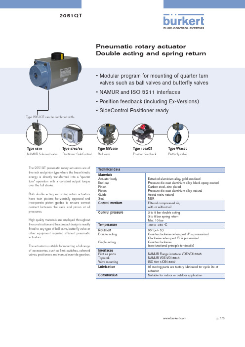
Pneumatic rotary actuatorDouble acting and spring return The 2051QT pneumatic rotary actuators are ofthe rack and pinion type where the linear kineticenergy is directly transformed into a “quarter turn” operation with a constant output torque over the full stroke.Both double acting and spring return actuators have twin pistons horizontally opposed and incorporate piston guides to ensure correct contact between the rack and pinion at all pressures.High quality materials are employed throughout the construction and the compact design is readily fitted to any type of ball valve, butterfly valve or other equipment requiring efficient pneumatic actuators.The actuator is suitable for mounting a full range of accessories, such as limit switches, solenoid valves, positioners and manual override gearbox.Extruded aluminium alloy, gold anodizedPressure die cast aluminium alloy, black epoxy coated Carbon steel, zinc platedType 6519NAMUR Solenoid valve Type 8792/93 Positioner SideControlType MV2650Ball valve Type 1062QTPosition feedbackType VV2670Butterfly valveFunctional principleDouble acting actuator (DA)Counter clockwise output operation is achieved by inserting pressure into Port ‘A’, to force piston apart thus rotating the actuator pinion counter clockwise. During the operation, air from the outer chambers is exhausted through Port ‘B’. Clockwise output operation is achieved by reverse of the above and inserting pressure into Port ‘B’.Single acting actuator (SR)Pressure applied to Port ‘A’ will cause the inner chambers to be pressurized, forcing the pistons outward to compress the springs. The pinion is rotated counter clockwise. Upon release of pressure through Port ‘A’ the springs will exert pressure to close the pistons and rotate the pinion clockwise rapidly. This action will often be used to close a 90oturn valve in shutdown mode.Pistons assembly variationsArrangement of springs for single acting actuatorActuator direction of rotation can be changed by switching both the pistons in accordance to the below diagramSprings can be added or removed according to torque requirement. It is recommended to install springs in accordance to the below diagramAir ConsumptionFree Air per stroke (Liters)Opening / Closing timeat 5.6 bar airWeight (kg)Torque Output (Nm) | Ordering Chart (other versions on request) Double acting actuator (DA)Torque Output (Nm) | Ordering Chart (other versions on request) Single acting actuator (SR)Dimensions [mm]AP01 to AP10 DA/ SR*** To be specified during order. Please refer to Ordering Chart.Parts listAP01 to AP10 DA/ SR* Suggested spare parts for routine maintenanceDimensions [mm]AP00 DAParts listAP00 DA* Suggested spare parts for routinemaintenanceDimensions [mm] - with accessoriesIn case of special application conditions,please consult for advice.We reserve the right to make technical changes without notice2051QT/EN/R1_12/2013With Type 6519 NAMUR solenoid valveWith declutchable manual override gearboxWith 879x positioner SideControlWith 1062QT position feedback。
气动执行器的产品说明书

S E R I E S P L S O L E N O I D V A L V E SDirect acting solenoid valves Series PL2/2-way - Normally Open (NO)3/2-way - Normally Closed (NC) and Normally Open (NO) 3/2-way - Universal (UNI)Series PL solenoid valves are available in the normally closed, normally open and universal versions. They can be mounted on single sub-bases or manifolds.Please note that all Series PL solenoid valves are supplied with direct current (DC). To operate in alternating current (AC), it is necessary to use the connector with bridge rectifier Mod. 125-900.»Application sectors: - Industrial Automation - Life Science - Transportation »Mounting on a single base (M5 connections) or on manifold (M5 or fittings Ø3 and Ø4)GENERAL DATATECHNICAL FEATURES Function OperationPneumatic connections Orifice diameterFlow coefficient kv (l/min) Operating pressure Operating temperature MediaResponse time Manual override Installation2/2 NO - 3/2 NC - 3/2 NO - 3/2 UNI direct acting poppet type on subbase 0.8 ... 1.6 mm 0.30 ... 0.62 0 ÷ 3.5 ... 10 bar0 ÷ 50 °C (FKM) / -50 ÷ 50 °C (low temperature NBR on demand)filtered air class [5:4:4] according to ISO 8573-1:2010 (max oil viscosity 32 cSt), inert gas ON <10 ms - OFF <15 msmono/bistable - PBT 3/2 versions onlyin any positionMATERIALS IN CONTACT WITH THE MEDIUM Body SealsInternal parts brass - PBT - PPSFKM - NBR - EPDM (on demand) brass - stainless steelELECTRICAL FEATURES VoltageVoltage tolerance Power consumption Duty cycleElectrical connection Protection class6 ... 110 V DC - other voltages on demand ±10% 1.2 ... 3 W ED 100%industry standard connector (9.4 mm) IP65 with connectorSpecial versions available on demandS E R I E S P L S O L E N O I D V A L V ES* 3/2 NO IN-LINE version: the position of the ports 1 - 2 - 3 is identical to 3/2 NC versionCODING EXAMPLES E R I E S P L S O L E N O I D V A L V E SSeries PL solenoid valve - 2/2-way NO - series PD interfaceSupplied with: 2x O-Rings2x M3x20 screws for mounting on metal or2x Ø3x23 screws for mounting on plastic(opt. P)* add - VOLTAGE - FIXING(see CODING EXAMPLE)Series PL solenoid valve - 3/2-way NCSupplied with: 1x interface seal2x M3x20 screws for mounting on metal or2x Ø3x23 screws for mounting on plastic (opt. P)Also available ST models forT amb. -50 ÷ 50 °C with NBR seals.* add - VOLTAGE - FIXING(see CODING EXAMPLE)S E R I E S P L S O L E N O I D V A L V E S2x M3x20 screws for mounting on metal or2x Ø3x23 screws for mounting on plastic (opt. P)Also available ST models forT amb. -50 ÷ 50 °C with NBR seals.* add - VOLTAGE - FIXING(see CODING EXAMPLE)Series PL solenoid valve - 3/2-way NO IN-LINESupplied with: 1x interface seal2x M3x20 screws for mounting on metal or2x Ø3x23 screws for mounting on plastic (opt. P)Also available ST models forT amb. -50 ÷ 50 °C with NBR seals.* add - VOLTAGE - FIXING(see CODING EXAMPLE)S E R I E S P L S O L E N O I D V A L V E S2x M3x20 screws for mounting on metal or2x Ø3x23 screws for mounting on plastic (opt. P)Also available models for T amb. -50 ÷ 50 °C with NBR sealsVacuum operation with max. pressurereduction* add - VOLTAGE - FIXING(see CODING EXAMPLE)S E R I E S P L S O L E N O I D V A L V ESSingle sub-base for 15mm size 2 way interfaceSingle sub-base suitable for 2-way solenoid valves Series PD and PL models PD000-2A..., PL000-9B... Use solenoid valves with fixing screws for metal (see codification page)Material: anodized aluminiumConnections: G1/8 threadsSingle sub-base for 3-way solenoid valve size 15 mmSingle sub-base suitable for Series P - PL - PN - W 3-way solenoid valveUse solenoid valves with screws for mounting on metal (see coding)Material: anodized aluminiumConnections: M5 threadsSingle manifold with rear outletsManifold suitable for Series P - PL - PN - W 3-way solenoid valveUse solenoid valves with screws for mounting on metal (see coding)Material: anodized aluminiumS E R I E S P L S O L E N O I D V A LV E SManifold - single side valve - frontal outletsManifold suitable for Series P - PL - PN - W 3-way solenoid valveUse solenoid valves with screws for mounting on metal (see coding)Can be fixed through DIN 46277/3 guide with the accessory PCF-E520.Material: anodized aluminiumManifold - double side valve - bottom outletsManifold suitable for Series P - PL - PN - W 3-way solenoid valveUse solenoid valves with screws for mounting on metal (see coding)Material: anodized aluminiumManifold - double side valve - frontal outletsManifold suitable for Series P - PL - PN - W 3-way solenoid valveUse solenoid valves with screws for mounting on metal (see coding)Can be fixed through DIN 46277/3 guide with the accessory PCF-E520.Material: anodized aluminiumS E R I E S P L S O L E N O I D V A L V ESPosition valve capSupplied with:1x position valve cap 1x interface seal2x screwsConnector Mod. 125-... - industrial std. 9.4 mmConnector Mod. 125-... - industrial std. 9.4 mm - 90° cableThe internal rectifier circuit of the connectorMod. 125-900 allows to use solenoid valves with different AC voltage, even if the voltage indicated onthe solenoid valve is DC.S E R I E S P L S O L E N O I D V A L V E SConnector Mod. 125-... - industrial std. 9.4 mm - in-line cablewithout electronicsConn. Mod. 125-... - ind. std. 9.4 mm - in-line cable+rectifierwith voltage rectifierAC/DC。
气动执行机构(BETTIS)操作维护手册

第二章气动执行机构(BETTIS)操作维护手册(一)BETTIS气动执行机构(ESDV阀)1 设备简介图1-2-1 ESDV阀门执行机构实际安装图图1-2-2 ESDV阀执行机构结构图1- 压力锁紧机构;2- Powr-swivl 活塞杆;3- Acculine 轴传动装置;4- NAMIR ;5- 可更换轴承;6- 推力轴套导向块;7- 共轭滚针推杆;8- 过载控制装置;9- 弹簧组件;10- 吊环;11- 环环紧扣;12- MSS 或ISO 执行机构/阀接口;13- 排气口;14- 压力槽;15- 双向行程限位;16- 内部双连杆。
2 使用操作方法1、执行机构手轮;2、电磁阀;3、电磁阀;4、过滤减压装置;5、限位开关;6、继电器;7、排气阀;8、测试开关;10、速度控制开关;11、电磁阀。
11 ♦●❍ ⏹ ☐ ❑☐图1-2-3 ESDV阀门执行机构工作原理图2.2 ESDV阀门执行机构控制2.2.1 现场手动开关手轮通过执行机构配套的手轮(或液压手轮)装置选择手动/气动,逆时针旋转手轮,通过液压装置可以现场打开阀门;顺时针旋转手轮,通过液压装置可以现场关闭阀门;手轮处于中间位置时,执行机构处于远程气动状态,通过站控(中控)系统能够远程控制打开(或关闭)阀门。
2.2.2 远程自动操作正常工作状态下,ESD电磁阀(冗余)励磁,由于该电磁阀为NC,励磁时电磁阀导通,导致ESD先导阀(冗余)导通(与ESD电磁阀相连的),压缩空气进入气缸,压缩弹簧,执行机构动作,阀门打开。
当发生紧急情况时,ESD电磁阀(冗余)失电,电磁阀断开,导致先导阀(冗余)断开(与ESD电磁阀相连的),执行机构气缸内的压缩空气通过该先导阀释放,弹簧复位,阀门关闭。
2.2.3 部分冲程测试正常工作状态下,部分冲程测试电磁阀不带电,该电磁阀为NO,失电时电磁阀导通,导致先导阀导通(与部分冲程测试电磁阀相连的),此时气源接通,阀门正常工作。
Parker Pneumatic N Series 气动阀门说明书
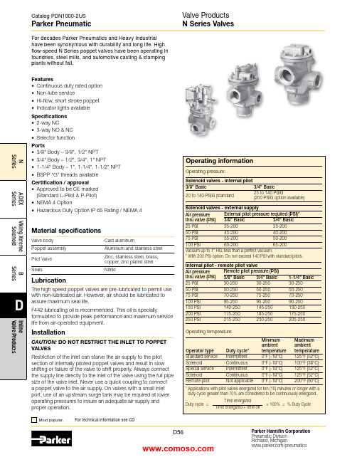
Material specificationsValve body Cast aluminumPoppet assembly Aluminum and stainless steel Pilot Valve Zinc, stainless steel, brass,copper, zinc plated steel SealsNitrileFeatures• Continuous duty rated option • Non-lube service• Hi-flow, short stroke poppet • Indicator lights available Specifications • 2-way NC• 3-way NO & NC • Selector functionPorts• 3/8" Body – 3/8", 1/2" NPT • 3/4" Body – 1/2", 3/4", 1" NPT• 1-1/4" Body – 1", 1-1/4", 1-1/2" NPT • BSPP “G” threads availableCertification / approval• Approved to be CE marked (Standard L-Pilot & P-Pilot)• NEMA 4 Option• Hazardous Duty Option IP 65 Rating / NEMA 4LubricationThe high speed poppet valves are pre-lubricated to permit use with non-lubricated air. However, air should be lubricated to assure maximum seal life.F442 lubricating oil is recommended. This oil is speciallyformulated to provide peak performance and maximum service life from air-operated equipment.InstallationCAUTION: DO NOT RESTRICT THE INLET TO POPPET VALVESRestriction of the inlet can starve the air supply to the pilot section of internally piloted poppet valves and result in slow shifting or failure of the valve to shift properly. Always connect the supply line directly to the inlet of the valve using the full pipe size of the valve inlet. Never use a quick coupling to connect a poppet valve to the air supply. On valves with a small inlet port, use of an upstream surge tank may be required at lower operating pressures to insure an adequate air supply and proper operation.Single Solenoid, Locking manual override, internal “P” pilot 140 PSI, standard service, junction box w/ light.Body In / cyl Exhaust 2-way, 2-position 3-way, 2-position 3-way, 2-positionSingle Remote Pilot, 1/4" NPT remote pilot port with internal pilot return.Body In / cyl Exhaust 2-way, 2-position 3-way, 2-position 3-way, 2-positionSingle Solenoid, Locking manual override, internal “P” pilot 125 PSI, standard service, P-pilot junction box w/ light.Body In / cyl Exhaust 2-way, 2-position 3-way, 2-position 3-way, 2-positionSingle Remote Pilot, 1/4" NPT remote pilot port with internal pilot return.Body In / cyl Exhaust 2-way, 2-position 3-way, 2-position 3-way, 2-positionParker PneumaticN Series Valves Model Number Index“N” Series 3/8", 3/4" & 1-1/4" Body Sizes - Solenoid ‘L’ PilotNote: BSPP is to the ISO 228 standard, and requires an R-BSPT male fitting.“N” Series 1-1/4" Body Sizes - Solenoid Hi-Flow ‘P’ PilotR-BSPT male fitting.Parker PneumaticReplacement PilotsDescriptionHazardous duty L-pilot NEMA 4 L-pilot Hazardous duty L-pilot - UL & CSA K0451025**N/AOverride typeLocking Non-Locking Locking Non-Locking Hazardous duty with override K0453025**K0452025**NEMA 4 with overrideK2553025**K255202549** Voltage code - 49 & 53N Series Valve Replacement PartsReplacement PilotsDescription Standard L-pilot Continuous duty L-pilot Override type Locking Non-locking Locking Non-locking Basic with overrideK0653035**K0652035**K0853025**K0852025**JIC with junction box & override K0656035**K0655035**K0856025**K0855025**JIC pilot with junction box &override & indicator lights (120VAC only)K0659035**K0658035**K0859025**K0858025**** Voltage code - (reference model index for availability)Replacement PilotsDescription Heavy duty P-Pilot Override type No override Non-locking Locking Basic with overrideK1351045**N/A N/AJIC with junction box & override N/A K1355045**K1356045**JIC Pilot with junction box & override & indicator lights (120VAC only)N/AK135804553K135904553** Voltage code - 49 & 53Voltage Code **Voltage Coil 60Hz 50Hz DC 19" Leads 72" Leads 4224——K593099—43—24—K593098—45——12K593094—49—— 24K593097—51——48—K59325453115——K593108—58—230—K593111—Coils for L-Pilot Operated ValvesCoils for P-Pilot Operated ValvesVoltage Code **Voltage Coil60Hz 50Hz DC 19" Leads 72" Leads 4012——K593007—41,4224—6K593003—45*——12K593010—49*——24 (Standard)K593014—79——24 (ArcSuppressed)K593271—51*——48—K59318553*120110—K593025—57*240240—K593035—60240220—K593035—61——120K593041—* Indicates voltages approved for solenoid operators designed for use inhazardous locations.NVoltage Code* *Internal Pilot -3/8" & 3/4" Basic BodyKey 3/8" Body3/4" Body Inch mm Inch mm A 1.5640 2.1354B 1.5038 1.9449C1.8146 1.3434D .5614.5614E 3/8-16UNC 7/16" deep 3/8-16UNC 9/16" deepF 1.7544 2.2557G 1.5038 1.5038H 5.921507.14181J3.1981 3.7595K 1.8847 2.4462N 1.4437 1.7845P 7.361968.58218Q2.31593.0984216891351051A 10AKey 3/8" Valve 3/4" Valve Description4*H14510H13676U-cup (3/8), o-ring (3/4)5K493002K493009Stem6K202001K202002Lower piston assy.7*H14509H13676U-cup (3/8), o-ring (3/4)8H17811H17813Washer (2)9H06326H06332Stop nut (2)10K103035K103053Bottom cap (N.C.)10A K092020K092034Bottom cap assy. (N.O.)11*K183049K183057Gasket 12K473014K473015Spring 13K563015K563017Adapter 14*K41RB72121K41RB72221O-ringKey3/8" Valve 3/4" Valve Description1—1/2" Tap K053075Body (N.C.)3/8" TapK0530223/4" Tap K0530761/2" Tap K0530231" Tap K0532201A—3/4" Tap K053077Body (N.O.)3/8" Tap K0530253/4" Tap K0530781/2" Tap K0530261" Tap K0532182K212001K212002Upper piston assy Top view indicates flow through 3-Way valve with coil de-energized.NOTE: For normal valve operation, override must be in “out” position.Service KitsInclude all parts normally required for in-service maintenance:3/8" Basic valve with standard service L -Pilots .................K352076 3/8" Basic valve with continuous duty L -Pilots .....................K3522763/4" Basic valve with standard service L -Pilots .................K3520773/4" Basic valve with continuous duty L -Pilots .....................K352277Exhaust PressureNormally Closed1351A 10A216891351410Key 3/8" Valve 3/4" Valve Description 4*K41RB72211H13676O-ring 5K493002K493009Stem6K202001K202002Lower piston assy.7*K41RB72210H13676O-ring 8H17811H17813Washer (2)9H06326H06332Stop nut (2)10K103035K103053Bottom cap (N.C.)10A K092020K092034Bottom cap assy. (N.O.)11K473014K473015Spring 12*K183049K183057Gasket 13K563016K563021Adapter 14*K41RB72121K41RB72221O-ringKey 3/8" Valve 3/4" Valve Description1—1/2" Tap K053067Body (N.C.)3/8" TapK0530193/4" Tap K0530691/2" Tap K0531571" Tap K0532211A—3/4" Tap K053065Body (N.O.)3/8" Tap K0530183/4" Tap K0530701/2" Tap K0530641" Tap K0532192K212001K212002Upper piston assy 3*H13648H13728SealNormally ClosedNormally OpenExternal Pilot -3/8" & 3/4" Basic BodyKey 3/8" Body 3/4" Body Inch mm Inch mm A 1.5640 2.1354B 1.5038 1.9449C1.8146 1.3434D .5614.5614E3/8-16UNC 7/16" deep 3/8-16UNC 9/16" deepF 1.7544 2.2557G 1.5038 1.5038H 6.421637.45189J 3.1981 3.7595K 1.8847 2.4462N1.4437 1.7845P 7.862008.89226Q2.31593.0984R4.341105.38137Top view indicates flow through 3-Way valve with coil de-energized.NOTE: For normal valve operation, override must be in “out” position.Service KitsInclude all parts normally required for in-service maintenance:3/8" Basic valve with standard service L -Pilots .................K3520763/8" Basic valve with continuous duty L -Pilots .....................K3522763/4" Basic valve with standard service L -Pilots .................K3520773/4" Basic valve with continuous duty L -Pilots .....................K352277Exhaust PressureTop view indicates flow through 3-Way valve with coil de-energized.NOTE: For normal valve operation, override must be in “out” position.Service KitsInclude all parts normally required for in-service maintenance:1-1/4" Basic valve with standard service P-Pilots ............K352078Exhaust Pressure5Key 1-1/4" Valve Description 4*H13728Seal 5K493016Stem6K313028Lower piston 7*H13728Seal 8H17817Washer 9H06338Stop nut10K092046Bottom cap (N.C.)10A K103061Bottom cap (N.O.)11*K183058Gasket 12K473016Spring 13K012003Adapter 14*K41RB72143O-ringKey1-1/4" Valve Description11" Tap K053111Body (N.C.)1-1/4" Tap K0531121-1/2" Tap K0531131A1" Tap K053114Body (N.O.)1-1/4" Tap K0531151-1/2" Tap K0531162K313029Upper piston assy 3*H13752O-ringInternal Pilot - 1-1/4" Basic BodyInternal Pilot - 1-1/4" Basic BodyKey 1-14" BodyInch mm A 3.0076B2.2557C 1.3434D 1.1930E 1/2-13 UNC 3/4 DeepF 3.1380G 1.5038H 9.30236J5.34136K 3.4487N2.3159P 11.14283Q4.56116Continuous Duty Pilot - 1-1/4" Basic BodyContinuous Duty Pilot - 1-1/4" Basic BodyKey 1-1/4" BodyInch mm A 3.0076B 2.2557C1.3434D 1.1930E 1/2-13 UNC 3/4 DeepF 3.1380G 1.5038H 9.02229J 5.34136K 3.4487N2.3159P 10.45265Q4.561165Key 1-1/4" Valve Description 4*H13728Seal 5K493016Stem6K313028Lower piston 7*H13728Seal 8H17817Washer 9H06338Stop nut10K092046Bottom cap (N.C.)10A K103061Bottom cap (N.O.)11*K183058Gasket 12K473016Spring 13K012003Adapter 14*K41RB72143O-ringKey1-1/4" Valve Description11" Tap K053111Body (N.C.)1-1/4" Tap K0531121-1/2" Tap K0531131A1" Tap K053114Body (N.O.)1-1/4" Tap K0531151-1/2" Tap K0531162K313029Upper piston assy Normally ClosedTop view indicates flow through 3-Way valve with coil de-energized.NOTE: For normal valve operation, override must be in “out” position.Service KitsInclude all parts normally required for in-service maintenance:1-1/4" Basic valve with continuous duty L -Pilot ...................K352080Exhaust PressureInternal Return - 3/8", 3/4", 1-1/4" Basic BodyKey3/8" Body 3/4" Body 1-1/4" Body Inch mm Inch mm Inch mmH 3.1981 3.7595 5.34136J 1.8848 2.4462 3.4487M 1.4437 1.7845 2.6667N 4.22107 5.311357.19183Q2.31593.09784.56116Key 3/8" Valve 3/4" Valve1-1/4" Valve Description 5K493002K493009K493016Stem6K202001K202002K313028Lower pistonassy.7*H13499H13676H13728Seal 8H17811H17813H17817Washer (2)9H06326H06332H06338Stop nut (2)10K092020K092034K092046Bottom cap(N.C.)10A K103035K103053K103061Bottom cap(N.O.)11*K183049K183057K183058Gasket 12K473014K473015K473016Spring 14*K41RB72121K41RB72221K41RB72143O-ring 21K123018K123021K123024CoverKey 3/8" Valve 3/4" Valve1-1/4" ValveDescription1—1/2" TapK0530751" Tap K053111Body (N.O.)3/8" Tap K0530223/4" Tap K0530761-1/4" Tap K0531121/2" Tap K0530231" Tap K0532201-1/2" Tap K0531131A—1/2" TapK0530771" Tap K053114Body (N.C.)3/8" Tap K0530253/4" Tap K0530781-1/4" Tap K0531151/2" Tap K0530261" Tap K0532181-1/2" Tap K0531162K212001K212002K313029Upper piston assy 3*H13648H13728H13752Seal 4*H14510H13676H13728Seal2152151A 7*10Service KitsInclude all parts normally required for in-service maintenance:3/8" Basic valve ........................K3520733/4" Basic valve .........................K3520741-1/4" Basic valve .....................K352075Normally ClosedTop view indicates flow through 3-Way valve.NOTE: For normal valve operation, override must be in “out” position.Exhaust PressureTop view indicates flow through 3-Way valve.NOTE: For normal valve operation, override must be in “out” position.Exhaust Pressure132151051A 7*Internal Return - 3/8", 3/4", 1-1/4" Basic BodyKey 3/8" Body 3/4" Body 1-1/4" Body Inch mm Inch mm Inch mm A 1.5640 2.1354 3.0076B 1.5038 1.9449 2.2557C 1.1329 1.1329 2.3860D .5614.5614 1.1930E 3/8–16UNC 7/16" deep 3/8– 16UNC 9/16" deep 1/2–13UNC 3/4" deep F 1.7544 2.2557 3.1379G 1.5640 2.1354 3.1379H 3.1981 3.7595 5.34136J 1.8848 2.4462 3.4487K 2.3159 3.0978 4.56116L 4.34110 5.381377.31186M5.311356.341617.88200N Left of centerOn center.53 13 1.0025Q1.4437 1.78452.3159Key 3/8" Valve 3/4" Valve1-1/4" Valve Description 5K493002K493009K493016Stem6K202001K202002K313028Lower pistonassy.7*H13499H13676H13728Seal 8H17811H17813H17817Washer (2)9H06326H06332H06338Stop nut (2)10K092020K092034K092046Bottom capassy. (N.C.)10A K103035K103053K103061Bottom cap(N.O.)11*K183049K183057K183058Gasket 12K473014K473015K473016Spring 13K563016K563021K563027Adapter 14*K41RB72121K41RB72221K41RB72143O-ring 21K323027K323027Not used CoverKey3/8" Valve 3/4" Valve 1-1/4" Valve Description11/4" Tap K0530111/2" Tap K0530671" Tap K053143Body (N.O.)—3/4" Tap K0530691-1/4" Tap K0531101/2" TapK0531571" Tap K0532211-1/2" Tap K0531461A 1/4" Tap K0530101/2" Tap K0530651" Tap K053159Body (N.C.)—3/4" Tap K0530701-1/4" Tap K0531441/2" Tap K0530641" Tap K053 2191-1/2" Tap K0531452K212001K212002K313029Upper piston assy 3*H13648H13728H13752Seal 4*H13529H13676H13728SealNormally ClosedService KitsInclude all parts normally required for in-service maintenance:3/8" Basic valve ........................K3520313/4" Basic valve ........................K3520561-1/4" Basic valve .....................K352083Catalog PDN1000-2USParker PneumaticParker Hannifin Corporation Pneumatic Division Richland, Michigan/pneumaticsD66Valve ProductsN Series Valve DimensionsInternal Return -3/8" & 3/4" Basic BodyKey 3/8" Body 3/4" Body 1-1/4" Body Inch mm Inch mm Inch mm A 1.5640 2.1354 3.0076B 1.5038 1.9449 2.2557C 1.1329 1.1329 2.3860D .5614.5614 1.1930E 3/8–16UNC 7/16" deep 3/8–16UNC 9/16" deep 1/2–13UNC 3/4" deep F 1.7544 2.2557 3.1379G 1.5640 2.1354 3.1379H 3.1981 3.7595 5.34136J 1.8848 2.4462 3.4487K .5013.5013.5013L .113.164.256M 1.4437 1.7845 2.6667N 4.22107 5.311357.19183P 4.78121 5.561417.53191Q2.31593.09784.56116Internal Return -3/8" & 3/4" Basic Body3/8" Body 3/4" Body 1-1/4" Body Key Inch mm Inch mm Inch mm A 1.5640 2.1354 3.0076B 1.5038 1.9449 2.2557C 1.1329 1.1329 2.3860D .5614.5614 1.1930E3/8–16UNC 7/16" deep 3/8–16UNC 9/16" deep 1/2–13UNC 3/4" deep F 1.7544 2.2557 3.1379G 1.5640 2.1354 3.1379H 3.1981 3.7595 5.34136J 1.8848 2.4462 3.4487K 2.3159 3.0978 4.56116L 4.34110 5.381377.31186M 5.31135 6.341617.88200N Left of centerOn center.53 13 1.0025Q1.44371.78452.3159Internal Return - 3/8" & 3/4" Basic BodyExternal Return - 3/8" & 3/4" Basic Body1/4 NPT 。
气动执行器手动操作说明书
Publication number F171EDate of issue 9/99Jackscrews provide a simple method of manually operating a pneumatically actuated valve. Power air supply may be unavailable during commissioning or emergency circumstances. The jackscrew may then be used to drive the piston of the pneumatic actuator reproducing the effect of the power air supply.1.0 Operating Instructions1.1Ensure power medium (air, gas, etc.) to actuator is notactive. Try to operate directional control valve locally. Ifpower medium is active at actuator, but below ratedpressure, ISOLATE the power medium from the actuator.1.2 Determine which way you wish to turn the valve shaft(most valves turn clockwise to close, but not all).1.3 Looking down on the actuator with the stop bolts awayfrom you (see document drawing #1256), operate the left-hand side jackscrew to turn the valve stem anti-clockwiseand operate the right-hand side jackscrew to turnclockwise.1.3.1On double acting actuators, ensure bothjackscrews are at full outboard position beforemanual operation of the valve.1.3.2On spring return actuators, only one jackscrewis provided as the spring operates the valve inthe other direction.1.4 Back off jamb nut at base of jackscrew.1.5 Ensure jackscrew is well lubricated with keystone GeneralPurpose 81L Grease or similar.1.6 Using wrench or handwheel, turn jackscrew clockwise topush actuator output through 90º. Do not exceed 90ºtravel; this may result in valve damage. Jackscrew torqueshould not exceed 800 inch/pounds. (90Nm).2.0 To Restore Actuator to Automatic Mode2.1Unscrew jackscrew to full outboard position.2.2Retighten jamb nut on cylinder side. Screw conical sealwasher against cylinder end flange before tightening jambnut. Tighten jamb nut to approximately 1,000 inch/pounds.(113Nm).3.0 Maintenance3.1Ensure stainless steel jackscrew threads are always wellgreased. This will make operation considerably easier. 4.0 Retrofitting JackscrewSee Document Drawing #1349.4.1Before attempting retrofit, ensure power medium isisolated from actuator and locked off.4.2Ensure no residual pressure is present in the actuatorcylinder.4.3Cylinder side jackscrew4.3.1 Disconnect air supply to cylinder end flange.4.3.2Remove four tie rod nuts 58.4.3.3Remove cylinder end flange 54 and seal 60.Technical information for‘P’ Range valve actuatorsTIS 40Operating and maintenanceInstructions - Jackscrews4.3.4Remove piston rod bolt 63.4.3.5Fit piston rod bolt 70 supplied with jackscrewretrofit module and tighten to recommendedtorque.4.3.6Coat hex nylon piece 71 with type 620 Loctitethen assemble into piston bolt 70.4.3.7Unscrew jackscrew to full outboard position.4.3.8Fit end flange with jackscrew and new sealprovided with retrofit module over the tie rods57.4.3.9Replace tie rod nuts 58 and tighten torecommended torque.4.3.10Retighten jamb nut 77 (as 2.2).4.4Rod cover side jackscrew4.4.1Remove piston rod cover bolts 202.4.4.2Remove piston rod cover 201.4.4.3 Fit piston rod bolt 210 supplied with jackscrew.Retrofit module and tighten to recommendedtorque4.4.4Coat hex nylon piece 211 with type 620 Loctitethen assemble into piston bolt 210.4.4.5Unscrew jackscrew to fully outboard position onjackscrew piston of cover.4.4.6Fit jackscrew piston rod cover over piston rod.Ensure flange gasket 51 and rod seal 50 are inplace.4.4.7Replace piston rod cover bolts 202 andlockwashers 203 and tighten to recommendedtorque.4.4.8Tighten jackscrew jamb nut.5.0Recommended Torques (lbs. ft.)Piston Bolt (Item 70)2505/8 UNC Grade 8210325 1 UNC Grade 88665001-1/4 UNC Grade 81750Piston Rod Bolt (Item 210)2505/8 UNC Grade 5150325 1 UNC Grade 55835001-1/4 UNC Grade 51097Tie Rod Nut (Item 58)250 05-085/8 UNC95250 10-123/4 UNC169325 10-143/4 UNC169500 123/4 UNC169Jackscrew Cover Bolt (Item 202)2501/2 UNC Grade 5753255/8 UNC Grade 5150500 1 UNC Grade 5525。
Parker Hannifin Pneumatic Division 气动分析手册说明书
Substituting in the formula, we have:
8.30 x 12 x 6.4 x .048
Cv =
= 1.06
1 x 28.8
Any valve, therefore, which has a Cv of at least 1.06, will
extend our cylinder the specified distance in the required
* Tabulated values are the solution of 68°F and G =1 for Air.
1 22.48
GT (P1 – P2) P2
where T is for
Table 3
Characteristics of the Major Valve Designs
A. Poppet 3-Way and 4-Way
D. Rotary Or Reciprocating Disc 4-Way, manually operated
1. Inexpensive 2. Versatility in manual actuation
Cv–Capacity Co-efficients–(sometimes called Flow Factors). Each flow path through the valve has its own Cv value. All Cv ratings for each valve cataloged on this page are listed on the front side of this sheet.
Cv
=
Q 22.48
GT (P1 – P2) P2
柏勒夫气动执行器说明书
BELEF Pneumatic Actuators Incorporate latest mechanical technology, materials available through designing, developing, testing and engineering application, we have obtained a high grade product with the characteristics of reliability, high performance, long cycle life, large adjustment, highest levels of corrosion protection, wide selection of model with easy and economy.柏勒夫气动执行器柏勒夫气动执行器综合了国际最新材料技术、精密加工技术、工业美术设计技术。
经过设计、开发、测试、生产和工程运用,该系列执行器具有运行可靠、工作寿命长、可调范围大、防腐性能高、规格多、选型灵活、经济实惠等优点。
性能、结构和设计特点● 挤压铝质(ASTM6005)缸体,内表面细磨精加工,内部和外部均采用高级防腐技术,气缸摩擦系数小,使用寿命长,抗腐蚀性能强。
● 双活塞齿轮齿条式设计,结构紧凑、安装位置对称、改变输出轴转向方便,使用寿命长、动作迅速。
活塞齿条背面装有复合轴承及导向环,动作精确、摩擦系数小、使用寿命延长。
● 组合式预负荷镀层弹簧,工作寿命长。
● 高精度齿轮和齿条,啮合间隙小、精度高,输出功率大。
● 不锈钢紧固件,安全美观,抗腐蚀性强。
● 采用国际规范尺寸:输出轴槽、螺孔;顶部安装孔尺寸符合NAMUR 标准;气源接口尺寸符合NAMUR 标准;底部安装孔尺寸符合IS05211、DIN3337标准,方便安装电磁阀限位开关等附件。
Design & Constructin of BAILEFU Pneumatic Actuators气动执行器结构Construction of Pneumatic Actuator● Extruded aluminum ASTM6005 body with bath internal and external corrosion protection having honed cylinder surface for longer life and low coefficient of friction.● Dual piston rack and pinion design for compact construction, symmetric mounting position, high-cycle fife and fast operation, reverse rotation can be accomplished in the field by simply inverting the pistons. ● Multiple bearings and guides on racks and pistons, low friction, high cycle life an d prevent shaft blowout.● Modular preloaded spring cartridge design, with coatedspring for simple versatile range, greater safely and corrosion resistance, longer cycle life.● Fully machined teeth on piston and pinion for accurate low backlash rack and pinion engagement, maximum efficlency. Stalnless steel fasteners for long term corroslon resistance● Full conformance to the latest specifications: IS05211,DIN 3337 and Namur or product inter changeahility and easy mounting of solenoids, limit switches and other aocessodes.have obtained a high grade product with the characteristics of reliability, high performance, long cycle life, large adjustment, highest levels of corrosion protection, wide selection of model with easy and economy.执行器零件、材料一览表Actuators Parts and Material Tablehave obtained a high grade product with the characteristics of reliability, high performance, long cycle life, large adjustment, highest levels of corrosion protection, wide selection of model with easy and economy.工作原理和输出扭矩Operating Principle and Out Torquehave obtained a high grade product with the characteristics of reliability, high performance, long cycle life, large adjustment, highest levels of corrosion protection, wide selection of model with easy and economy.工作原理和输出扭矩Operating Principle and Out Torquehave obtained a high grade product with the characteristics of reliability, high performance, long cycle life, large adjustment, highest levels of corrosion protection, wide selection of model with easy and economy.工作原理和输出扭矩Operating Principle and Out Torque柏勒夫气动执行器柏勒夫气动执行器综合了国际最新材料技术、精密加工技术、工业美术设计技术。
Bettis指导手册 G01 到 G10 型号 弹簧复位
中文版本BETTIS配有 M11 液压超控模块的G01 到 G10 型号弹簧复位气动执行机构的指导手册部件编号:127073E版本:“A”日期:2001 年 12 月目录页码第 1 章 - 简介 (2)1.1 服务信息概述...................................... Error! Bookmark not defined.1.2 定义 (2)1.3 安全信息概述 (2)1.4 BETTIS 参考资料 (2)1.5 服务支持项目 (3)1.6 润滑要求 (4)1.7 通用工具信息 (4)第 2 章 - 执行机构的拆卸 (5)2.1 拆卸概述 (5)2.2 气动动力模块的拆卸 (5)2.3 驱动模块的拆卸 (7)2.4 G01 到 G5 型号M11 液压超控缸的拆卸................ Error! Bookmark not defined.2.5 G7 到 G10 型号 M11 液压超控缸的拆卸 (9)第 3 章 - 执行机构的重新组装 (10)3.1 重装概述 (10)3.2 驱动模块的重新组装 (10)3.3 气动动力模块的重新组装 (14)3.4 G2 和 G3 早期型号的气动动力模块的重新组装 (16)3.5 G01 到 G5 型号 M11 液压超控缸的重新组装 (18)3.6 G7 到 G10 型号 M11 液压超控缸的重新组装 (19)3.7 测试执行机构 (20)第 4 章 - 现场改装 (21)4.1 失效模式转化(CW到CCW, 或CCW到CW) (21)4.2 将双作用式执行机构转换成附带超控缸组件的弹簧复位式执行机构 (21)第 5 章 - 模块的拆卸和安装 (22)5.1 M11 超控缸的拆卸 (22)5.2 M11 超控缸的安装 (23)5.3 弹簧模块的拆卸 (24)5.4 弹簧模块的安装 (25)5.5 气动动力模块的拆卸 (27)5.6 气动动力模块的安装 (28)5.7 POWR SWIVL模块的拆卸 (28)5.8 POWR SWIVL模块的安装 (29)第 6 章 - 执行机构支持信息 (30)6.1 M11 超控系统液体梯级表 (30)6.2 模块重量(根据产品编号和执行机构箱体尺寸) (30)6.3 G1 工具类型和扳手尺寸 (32)6.4 G2 工具类型和扳手尺寸 (32)6.5 G3 工具类型和扳手尺寸 (33)6.6 G4 工具类型和扳手尺寸 (33)6.7 G5 工具类型和扳手尺寸 (34)6.8 G7 工具类型和扳手尺寸 (35)6.9 G8 工具类型和扳手尺寸 (36)6.10 G10 工具类型和扳手尺寸 (37)第 1 章 - 简介1.1服务信息概述1.1.1 本维修手册可用作对带有一个气动动力模块和一个 M11 或 M11-S 液压超控模块的 BettisG01XXX-M11、G2XXX-M11、G3XXX-M11、G4XXX-M11、G5XXX-M11、G7XXX-M11、G8XXX-M11 和G10XXX-M11 双作用系列执行机构进行一般维护的指南。
- 1、下载文档前请自行甄别文档内容的完整性,平台不提供额外的编辑、内容补充、找答案等附加服务。
- 2、"仅部分预览"的文档,不可在线预览部分如存在完整性等问题,可反馈申请退款(可完整预览的文档不适用该条件!)。
- 3、如文档侵犯您的权益,请联系客服反馈,我们会尽快为您处理(人工客服工作时间:9:00-18:30)。
BELEF Pneumatic Actuators Incorporate latest mechanical technology, materials available through designing, developing, testing and engineering application, we have obtained a high grade product with the characteristics of reliability, high performance, long cycle life, large adjustment, highest levels of corrosion protection, wide selection of model with easy and economy.
柏勒夫气动执行器
柏勒夫气动执行器综合了国际最新材料技术、精密加工技术、工业美术设计技术。
经过设计、开发、测试、生产和工程运用,该系列执行器具有运行可靠、工作寿命长、可调范围大、防腐性能高、规格多、选型灵活、经济实惠等优点。
性能、结构和设计特点
● 挤压铝质(ASTM6005)缸体,内表面细磨精加工,内部和外部均采用高级防腐技术,气缸摩擦系数小,
使用寿命长,抗腐蚀性能强。
● 双活塞齿轮齿条式设计,结构紧凑、安装位置对称、改变输出轴转向方便,使用寿命长、动作迅速。
活
塞齿条背面装有复合轴承及导向环,动作精确、摩擦系数小、使用寿命延长。
● 组合式预负荷镀层弹簧,工作寿命长。
● 高精度齿轮和齿条,啮合间隙小、精度高,输出功率大。
● 不锈钢紧固件,安全美观,抗腐蚀性强。
● 采用国际规范尺寸:输出轴槽、螺孔;顶部安装孔尺寸符合NAMUR 标准;气源接口尺寸符合NAMUR 标准;
底部安装孔尺寸符合IS05211、DIN3337标准,方便安装电磁阀限位开关等附件。
Design & Constructin of BAILEFU Pneumatic Actuators
气动执行器结构
Construction of Pneumatic Actuator
● Extruded aluminum ASTM6005 body with bath internal and external corrosion protection having honed
cylinder surface for longer life and low coefficient of friction.
● Dual piston rack and pinion design for compact construction, symmetric mounting position, high-cycle
fife and fast operation, reverse rotation can be accomplished in the field by simply inverting the pistons.
● Multiple bearings and guides on racks and pistons, low friction, high cycle life an d prevent shaft
blowout.
● Modular preloaded spring cartridge design, with coatedspring for simple versatile range, greater safely
and corrosion resistance, longer cycle life.
● Fully machined teeth on piston and pinion for accurate low backlash rack and pinion engagement,
maximum efficlency. Stalnless steel fasteners for long term corroslon resistance
● Full conformance to the latest specifications: IS05211,DIN 3337 and Namur or product inter changeahility and easy mounting of solenoids, limit switches and other aocessodes.
have obtained a high grade product with the characteristics of reliability, high performance, long cycle life, large adjustment, highest levels of corrosion protection, wide selection of model with easy and economy.
执行器零件、材料一览表Actuators Parts and Material Table
have obtained a high grade product with the characteristics of reliability, high performance, long cycle life, large adjustment, highest levels of corrosion protection, wide selection of model with easy and economy.
工作原理和输出扭矩Operating Principle and Out Torque
have obtained a high grade product with the characteristics of reliability, high performance, long cycle life, large adjustment, highest levels of corrosion protection, wide selection of model with easy and economy.
工作原理和输出扭矩Operating Principle and Out Torque
have obtained a high grade product with the characteristics of reliability, high performance, long cycle life, large adjustment, highest levels of corrosion protection, wide selection of model with easy and economy.
工作原理和输出扭矩Operating Principle and Out Torque。