DLX指令集结构
体系结构简答题
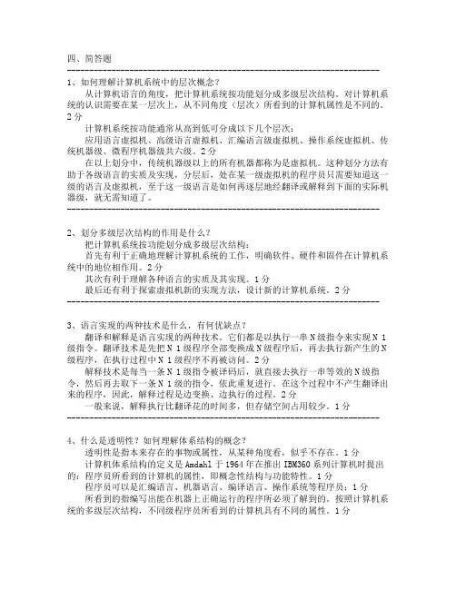
四、简答题---------------------------------------------------------------------- 1、如何理解计算机系统中的层次概念?从计算机语言的角度,把计算机系统按功能划分成多级层次结构。
对计算机系统的认识需要在某一层次上,从不同角度(层次)所看到的计算机属性是不同的。
2分计算机系统按功能通常从高到低可分成以下几个层次:应用语言虚拟机、高级语言虚拟机、汇编语言级虚拟机、操作系统虚拟机、传统机器级、微程序机器级共六级。
2分在以上划分中,传统机器级以上的所有机器都称为是虚拟机。
这种划分方法有助于各级语言的实质及实现,分层后,处在某一级虚拟机的程序员只需要知道这一级的语言及虚拟机,至于这一级语言是如何再逐层地经翻译或解释到下面的实际机器级,就无需知道了。
----------------------------------------------------------------------2、划分多级层次结构的作用是什么?把计算机系统按功能划分成多级层次结构:首先有利于正确地理解计算机系统的工作,明确软件、硬件和固件在计算机系统中的地位相作用。
2分其次有利于理解各种语言的实质及其实现。
1分最后还有利于探索虚拟机新的实现方法,设计新的计算机系统。
2分----------------------------------------------------------------------3、语言实现的两种技术是什么,有何优缺点?翻译和解释是语言实现的两种技术。
它们都是以执行一串N级指令来实现N 1级指令。
翻译技术是先把N 1级程序全部变换成N级程序后,再去执行新产生的N 级程序,在执行过程中N 1级程序不再被访问。
2分解释技术是每当一条N 1级指令被译码后,就直接去执行一串等效的N级指令,然后再去取下一条N 1级的指令,依此重复进行。
在这个过程中不产生翻译出来的程序,因此,解释过程是边变换、边执行的过程。
DLX指令集实验
DLX指令集实验
实验报告
北京交通大学计算机与信息技术学院计科1104(进修生)03班
房皓13410801
2014/3/26
一.实验目的
1. 熟悉DLX的指令集格式。
二.实验内容
1. 熟悉winDLX模拟器,并确定指令格式中各个域的具体值。
包括如下内容:
①将附件中的WinDLX.Zip文件解压到你的电脑中。
②阅读附件中的wdlxtut.pdf文件,并按其中的步骤操作、学习winDLX
模拟器。
③对于FACT.S程序,请从中选出10条程序,并对于其中每条指令,指
出它是哪种指令(R-type,I-type,还是J-type),并参照教科书57
页图,填写指令格式中各个域的二进制值(提示:将程序载入到模拟
器后,可在CODE子窗口中观察到)。
为了清楚,最好用填表的形式。
2. 用DLX汇编语言编写一个冒泡排序程序。
并在模拟器上调试成功。
要求:
①独立完成。
(如果你想了解多DLX指令集,可自己在百度上搜索。
)
②程序有比较详细的注释。
③对程序的设计思路有一个比较清楚的说明。
三.实验结果
1、对于FACT.S程序中所选的10条指令的分析:
分析所用的是code子窗口中提供的内容,如下图所示
图1:code子窗口
分析结果:
四.实验总结
通过本次实验,我锻炼了自己动手操作能力,并对理论知识有了进一步的了解,对winDLX流水线模拟器有了初步的了解,并熟悉了DLX的指令集格式。
DLX指令集-1
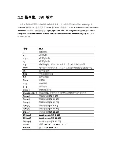
DLX 指令集, BYU 版本注意8条指令已经加入到此版本的指令集中。
这些指令既没有出现在Hennessy 和Patterson的课本中,也没有列在Sailer 和Kaeli 合编的"The DLX Instruction Set Architecture Handbook"一书中。
新的指令是:sgeu, sgtu, sleu, sltu -- all compares using unsigned values -- along with an immediate form of each. The new instructions were added to simplify the DLX backend for lcc.标记符号意义x_y bit y of xx_y..z bits y to z of x (right justified)x^y xx....x (x repeated y times)x##y xy (x concatenated with y)IR 指令寄存器IAR 中断地址寄存器PC 程序计数器R[rega] 整数寄存器[IR_6..10]R[regb] 整数寄存器[IR_11..15]R[regc] 整数寄存器[IR_16..20]F[frega] 浮点寄存器[IR_6..10]F[fregb] 浮点寄存器[IR_11..15]F[fregc] 浮点寄存器[IR_16..20]D[drega] double register[IR_6..10]D[dregb] double register[IR_11..15]D[dregc] double register[IR_16..20]imm16 value of (IR_16)^16 ## IR_16..31uimm16 value of 0^16 ## IR_16..31imm26 value of (IR_6)^6 ## IR_6..0fps floating point status bit<-- a 32-bit transfer<--n an n-bit transfer注意/假设∙Bits are numbered from 0 (the most significant bit) to 31 (the least significant bit).∙All transfers are 32 bits unless otherwise specified, with the exception of double precision fp operations which are 64 bit transfers unless otherwise noted.∙All integer operations are on 32-bit integers.∙All assignments to integer register[x] are conditional on x not being zero. Register 0 has a hardwired {\em zero} value and cannot be modified.∙Double register[x] is a 64 bit quantity that represents the same storage as fp register[x] and fp register[x+1]. Only even values of x are allowed (double register addresses are aligned).Single precision floating point is 32 bits and double precision floating point is 64 bits.The exact floating point format used is that of the machine on which the simulator is running.∙The specifications for branches and jumps assume that the PC has not yet been incremented (for the next instruction) when the specified actions are performed. Note that this does not represent the actual behavior in any reasonable pipelined implementation; it is assumed merely to simplify the description.Memory will be stored in big endian format and all effective addresses must be aligned with the data type.InstructionsaddEx: add r1,r2,r3R[regc] <-- R[rega] + R[regb]All are signed integers.adddEx: addd f4,f4,f6D[dregc] <-- D[drega] + D[dregb]All are double precision floating point numbers.addfEx: addf f3,f4,f5F[fregc] <-- F[frega] + F[fregb]All are single precision floating point numbers.addiEx: addi r5,r2,#5R[regb] <-- R[rega] + imm16All are signed integers.adduEx: addu r2,r3,r4R[regc] <-- R[rega] + R[regb]All are unsigned integers.adduiEx: addui r2,r3,#28R[regb] <-- R[rega] + uimm16All are unsigned integers.andEx: and r2,r3,r4R[regc] <-- R[rega] & R[regb]All are unsigned integers. Logical `and' is performed on a bitwise basis.andiEx: andi r3,r4,#5R[regb] <-- R[rega] & uimm16All are unsigned integers. Logical `and' is performed on a bitwise basis.Ex: beqz r1,labelif (R[rega] == 0) PC <-- PC + imm16 + 4bfpfEx: bfpf labelif (fps == 0) PC <-- PC + imm16 + 4fps is the floating point status bit.bfptEx: bfpt labelif (fps == 1) PC <-- PC + imm16 + 4fps is the floating point status bit.bnezEx: bnez r1,labelif (R[rega] != 0) PC <-- PC + imm16 + 4cvtd2fEx: cvtd2f f1,f4F[fregc] <-- (float) D[drega]Converts double precision floating point value to single precision floating point value.cvtd2iEx: cvtd2i f1,f0F[fregc] <-- (int) D[drega]Converts double precision floating point value to integer.cvtf2dEx: cvtf2d f4,f9D[dregc] <-- (double) F[frega]Converts single precision float to double.cvtf2iEx: cvtf2i f3,f4F[fregc] <-- (int) F[frega]Converts single precision float to integer.cvti2dEx: cvti2d f2,f9D[dregc] <-- (double) F[frega]Converts a signed integer to double precision float.Ex: cvti2f f2,f5F[fregc] <-- (float) F[frega]Converts a signed integer to single precision float.divEx: div f2,f2,f3F[fregc] <-- F[frega] / F[fregb]All are signed integers.divdEx: divd f4,f4,f6D[dregc] <-- D[drega] / D[dregb]All are double precision floats.divfEx: divf f2,f3,f6F[fregc] <-- F[frega] / F[fregb]All are single precision floats.divuEx: divu f2,f3,f4F[fregc] <-- F[frega] / F[fregb]All are unsigned integers.eqdEx: eqd f2,f4if (D[drega] == D[dregb]) fps = 1 else fps = 0Both are double precision floats.eqfEx: eqf f3,f5if (F[frega] == F[fregb]) fps = 1 else fps = 0Both are single precision floats.gedEx: ged f8,f6if (D[drega] >= D[dregb]) fps = 1 else fps = 0Both are double precision floats.gefEx: gef f3,f6if (F[frega] >= F[fregb]) fps = 1 else fps = 0Both are single precision floats.gtdEx: gtd f8,f6if (D[drega] > D[dregb]) fps = 1 else fps = 0Both are double precision floats.gtfEx: gtf f3,f6if (F[frega] > F[fregb]) fps = 1 else fps = 0Both are single precision floats.jEx: j labelPC <-- PC + imm26 + 4Unconditionally jumps relative to the PC of the next instruction. imm26 is a 26-bit signed integer.jalEx: jal labelR31 <-- PC + 8; PC <-- PC + imm26 + 4Saves a return address in register 31 and jumps relative to the PC of the next instruction. imm26 is a 26-bit signed integer.jalrEx: jalr r2R31 <-- PC + 8; PC <-- R[rega]Saves a return address in register 31 and does an absolute jump to the target address contained in R[rega].jrEx: jr r3PC <-- R[rega]R[rega] is treated as an unsigned integer. Does an absolute jump to the target address contained in R[rega].lbEx: lb r1,40-4(r2)R[regb] <-- (sign extended) M[imm16 + R[rega]]One byte of data is read from the effective address computed by adding signed integer imm16 and signed integer R[rega]. The byte from memory is then sign extended to 32-bits and stored in register R[regb].lbuEx: lbu r2,label-786+4(r3)R[regb] <-- 0^24 ## M[imm16 + R[rega]]One byte of data is read from the effective address computed by addingsigned integer imm16 and signed integer R[rega]. The byte from memory is then zero extended to 32 bits and stored in register R[regb].ldEx: ld f2,240(r1)D[dregb] <--64 M[imm16 + R[rega]]Two words of data are read from the effective address computed by adding signed integer imm16 and unsigned integer R[rega] and stored in double register D[dregb]. This is equivalent to two lf instructions:F[fregb] <-- M[imm16 + R[rega]]F[freg(b+1)] <-- M[imm16 + R[rega] + 4]where F[freg(b+1)] is the next fp register after F[fregb] in sequence, and all values aresimply copied and not converted.)ledEx: led f8,f6if (D[drega] <= D[dregb]) fps = 1 else fps = 0Both are double precision floats.lefEx: lef f3,f6if (F[frega] <= F[fregb]) fps = 1 else fps = 0Both are single precision floats.lfEx: lf f6,76(r4)F[fregb] <-- M[imm16 + R[rega]]One word of data is read from the effective address computed byadding signed integer imm16 and signed integer R[rega] and stored in fp register F[fregb].lhEx: lh r1,32(r3)R[regb] <-- (sign extended) M[imm16 + R[rega]]Two bytes of data are read from the effective address computed by adding signed integer imm16 and signed integer R[rega]. The address must be half-word aligned. The half-word from memory is then sign extended to 32 bits and stored in register R[regb].lhiEx: lhi r3,#-40R[regb] <-- imm16 ## 0^16Loads the 16 bit immediate value imm16 into the most significant half of an integer register and clears the least significant half.lhuEx: lhu r2,-40+4(r3)R[regb] <-- 0^16 ## M[imm16 + R[rega]]Two bytes of data are read from the effective address computed by adding signed integer imm16 and signed integer R[rega]. The address must be half-word aligned. The half-word from memory is then zero extended to 32 bits and stored in register R[regb].ltdEx: ltd f8,f6if (D[drega] < D[dregb]) fps = 1 else fps = 0Both are double precision floats.ltfEx: ltf f3,f6if (F[frega] < F[fregb]) fps = 1 else fps = 0Both are single precision floats.lwEx: lw r19,label+63(r8)R[regb] <-- M[imm16 + R[rega]]One word is read from the effective address computed by adding signed integer imm16 and unsigned integer R[rega] and is stored in R[regb].movdEx: movd f2,f4D[dregc] <-- D[drega]Copies two words from double register D[drega] to double register D[dregc].movfEx: movf f1,f2F[fregc] <-- F[frega]Copies one word from fp register F[frega] to fp register F[fregc].movfp2iEx: movfp2i r3,f0R[regc] <-- F[frega]Copies one word from fp register F[frega] to integer registerR[regc].movi2fpEx: movi2fp f0,r3F[fregc] <-- R[rega]Copies one word from integer register R[rega] to fp registerF[fregc].movi2sEx: movi2s r1UnspecifiedCopies one word from integer register R[rega] to a special register.movs2iEx: movs2i r2UnspecifiedCopies one word from a special register to integer register R[rega].multEx: mult f2,f3,f4F[fregc] <-- F[frega] * F[fregb]All are signed integers.multdEx: multd f2,f4,f6D[dregc] <-- D[drega] * D[dregb]All are double precision floats.multfEx: multf f3,f4,f5F[fregc] <-- F[frega] * F[fregb]All are single precision floats.multuEx: multu f2,f3,f4F[fregc] <-- F[frega] * F[fregb]All are unsigned integers.nedEx: ned f8,f6if (D[drega] != D[dregb]) fps = 1 else fps = 0Both are double precision floats.nefEx: nef f3,f6if (F[frega] != F[fregb]) fps = 1 else fps = 0Both are single precision floats.nopEx: nopIdles one cycle.orEx: or r2,r3,r4R[regc] <-- R[rega] | R[regb]All are unsigned integers. Logical `or' is performed on a bitwise basis.oriEx: ori r3,r4,#5R[regb] <-- R[rega] | uimm16All are unsigned integers. Logical `or' is performed on a bitwise basis.rfeEx: rfeUnspecifiedReturn from exception.sbEx: sb label-41(r3),r2M[imm16 + R[rega]] <--8 R[regb]_24..31One byte of data from the least significant byte of register R[regb] is written to the effective address computed by adding signed integer imm16 and signed integer R[rega].sdEx: sd 200(r4),f6M[imm16 + R[rega]] <--64 D[dregb]Two words from double register D[dregb] are written to the effective address computed by adding signed integer imm16 and signed integer R[rega].seqEx: seq r1,r2,r3if (R[rega] == R[regb]) R[regc] <-- 1 else R[regc] <-- 0All are signed integers.seqiEx: seqi r14,r3,#3if (R[rega] == imm16) R[regb] <-- 1 else R[regb] <-- 0All are signed integers.sfEx: sf 121(r3),f1M[imm16 + R[rega]] <-- F[fregb]One word from fp register F[fregb] is written to the effective address computed by adding signed integer imm16 and signed integer R[rega].sgeEx: sge r1,r3,r4if (R[rega] >= R[regb]) R[regc] <-- 1 else R[regc] <-- 0All are signed integers.sgeiEx: sgei r2,r1,#6if (R[rega] >= imm16) R[regb] <-- 1 else R[regb] <-- 0All are signed integers.sgeuEx: sgeu r1,r3,r4if (R[rega] >= R[regb]) R[regc] <-- 1 else R[regc] <-- 0All are unsigned integers.sgeuiEx: sgeui r2,r1,#6if (R[rega] >= uimm16) R[regb] <-- 1 else R[regb] <-- 0All are unsigned integers.sgtEx: sgt r4,r5,r6if (R[rega] > R[regb]) R[regc] <-- 1 else R[regc] <-- 0All are signed integers.sgtiEx: sgti r1,r2,#-3000if (R[rega] > imm16) R[regb] <-- 1 else R[regb] <-- 0All are signed integers.sgtuEx: sgtu r4,r5,r6if (R[rega] > R[regb]) R[regc] <-- 1 else R[regc] <-- 0All are unsigned integers.sgtuiEx: sgtui r1,r2,#3000if (R[rega] > uimm16) R[regb] <-- 1 else R[regb] <-- 0All are unsigned integers.shEx: sh 421(r3),r5M[imm16 + R[rega]] <--16 R[regb]_16..31Two bytes of data from the least significant half of register R[regb] are written to the effective address computed by adding signed integer imm16 and unsigned integer R[rega]. The effective address must be halfword aligned.sleEx: sle r1,r2,r3if (R[rega] <= R[regb]) R[regc] <-- 1 else R[regc] <-- 0All are signed integers.sleiEx: slei r8,r5,#345if (R[rega] <= imm16) R[regb] <-- 1 else R[regb] <-- 0All are signed integers.sleuEx: sleu r1,r2,r3if (R[rega] <= R[regb]) R[regc] <-- 1 else R[regc] <-- 0All are unsigned integers.sleuiEx: sleui r8,r5,#345if (R[rega] <= uimm16) R[regb] <-- 1 else R[regb] <-- 0All are unsigned integers.sllEx: sll r6,r7,r11R[regc] <-- R[rega] << R[regb]_27..31All are unsigned integers. R[rega] is logically shifted left by the low five bits of R[regb]. Zeros are shifted into theleast-significant bit.slliEx: slli r1,r2,#3R[regb] <-- R[rega] << uimm16_27..31All are unsigned integers. R[rega] is logically shifted left by the low five bits of uimm16. Zeros are shifted into theleast-significant bit. (Actually only the bottom five bits ofR[regb] are used.)slt Ex: slt r3,r4,r5if (R[rega] < R[regb]) R[regc] <-- 1 else R[regc] <-- 0All are signed integers.sltiEx: slti r1,r2,#22if (R[rega] < imm16) R[regb] <-- 1 else R[regb] <-- 0All are signed integers.sltuEx: sltu r3,r4,r5if (R[rega] < R[regb]) R[regc] <-- 1 else R[regc] <-- 0All are unsigned integers.sltuiEx: sltui r1,r2,#22if (R[rega] < uimm16) R[regb] <-- 1 else R[regb] <-- 0All are unsigned integers.sneEx: sne r1,r2,r3if (R[rega] != R[regb]) R[regc] <-- 1 else R[regc] <-- 0All are signed integers.sneiEx: snei r4,r5,#89if (R[rega] != imm16) R[regb] <-- 1 else R[regb] <-- 0All are signed integers.sraEx: sra r1,r2,r3R[regc] <-- (R[rega]_0)^R[regb] ## (R[rega]>>R[regb])_R[regb]..31 R[rega] and R[regc] are signed integers. R[regb] is an unsigned integer. R[rega] is arithmetically shifted right by R[regb]. The sign bit is shifted into the most-significant bit. (Actually uses only the five low order bits of R[regb].)sraiEx: srai r2,r3,#5R[regb] <-- (R[rega]_31)^uimm16 ## (R[rega]>>uimm16)_uimm16..31 R[rega] and R[regc] are signed integers. uimm16 is an unsigned integer. R[rega] is arithmetically shifted right by R[regb]. The sign bit is shifted into the most-significant bit. (Actually uses only the five low order bits of uimm16.)srlEx: srl r15,r2,r3R[regc] <-- R[rega] >> R[regb]_27..31All are unsigned integers. R[rega] is arithmetically shifted right by R[regb]. Zeros are shifted into the most significant bit.srliEx: srli r1,r2,#5R[regb] <-- R[rega] >> uimm16_27..31All are unsigned integers. R[rega] is arithmetically shifted right by uimm16. Zeros are shifted into the most significant bit.subEx: sub r3,r2,r1Ex: R[regc] <-- R[rega] - R[regb]All are signed integers.subdEx: subd f2,f4,f6D[dregc] <-- D[drega] - D[dregb]All are double precision floats.subfEx: subf f3,f4,f6F[fregc] <-- F[frega] - F[fregb]All are single precision floats.subiEx: subi r15,r16,#964R[regb] <-- R[rega] - imm16All are signed integers.subuEx: subu r3,r2,r1R[regc] <-- R[rega] - R[regb]All are unsigned integers.subuiEx: subui r1,r2,#53R[regb] <-- R[rega] - uimm16All are unsigned integers.swEx: sw 21(r13),r6M[imm16 + R[rega]] <-- R[regb]One word from integer register R[regb] is written to the effective address computed by adding signed integer imm16 and unsigned integer R[rega].trapEx: trap #3Execute trap with number in immediate fieldSaves state and jumps to an operating system procedure located at an address in the interrupt vector table. In our systems, this is simulated by calling the procedure corresponding to the trap number.xorEx: xor r2,r3,r4R[regc] <-- F[rega] XOR R[regb]All are unsigned integers. Logical 'xor' is performed on a bitwise basis.xoriEx: xori r3,r4,#5R[regb] <-- R[rega] XOR uimm16All are unsigned integers. Logical 'xor' is performed on a bitwise basis.Instruction EncodingThe general instruction layout for DLX is shown on page 99 of H&P (2nd Ed.). This specifies the encodings (the 6-bit opcode and the 11-bit function code) assumed in the BYU ECEn Department's tool set. (This is not intended to be compatible with DLX tools from any other source. Encodings were chosen to keep things simple.) The following is a portion of an include file used by the assembler and simulator. Note that it defines a struct for each instruction, specifying (1) the mnemonic used by the assembler and disassemblers, (2) the 6 bit opcode value, (3) the value used in the func bits./* --------------------- dlxdef.h ------------------------- */struct mapper{char *name;int op;int func;int optype;};struct mapper mainops[] ={{"special", 0x00, 0x00, UNIMP},{"addi", 0x02, 0x00, REG2IMM},{"addui", 0x03, 0x00, REG2IMM},{"andi", 0x04, 0x00, REG2IMM},{"beqz", 0x05, 0x00, REGLAB},{"bfpf", 0x06, 0x00, LEXP16},{"bfpt", 0x07, 0x00, LEXP16},{"bnez", 0x08, 0x00, REGLAB},{"j", 0x09, 0x00, LEXP26},{"jal", 0x0a, 0x00, LEXP26},{"jalr", 0x0b, 0x00, IREG1},{"jr", 0x0c, 0x00, IREG1},{"lb", 0x0d, 0x00, LOADI},{"lbu", 0x0e, 0x00, LOADI},{"ld", 0x0f, 0x00, LOADD},{"lf", 0x10, 0x00, LOADF},{"lh", 0x11, 0x00, LOADI},{"lhi", 0x12, 0x00, REG1IMM},{"lhu", 0x13, 0x00, LOADI},{"lw", 0x14, 0x00, LOADI},{"ori", 0x15, 0x00, REG2IMM},{"rfe", 0x16, 0x00, UNIMP},{"sb", 0x17, 0x00, STRI},{"sd", 0x18, 0x00, STRD},{"seqi", 0x19, 0x00, REG2IMM},{"sf", 0x1a, 0x00, STRF},{"sgei", 0x1b, 0x00, REG2IMM},{"sgeui", 0x1c, 0x00, REG2IMM}, /* added instruction */ {"sgti", 0x1d, 0x00, REG2IMM},{"sgtui", 0x1e, 0x00, REG2IMM}, /* added instruction */ {"sh", 0x1f, 0x00, STRI},{"slei", 0x20, 0x00, REG2IMM},{"sleui", 0x21, 0x00, REG2IMM}, /* added instruction */ {"slli", 0x22, 0x00, REG2IMM},{"slti", 0x23, 0x00, REG2IMM},{"sltui", 0x24, 0x00, REG2IMM}, /* added instruction */ {"snei", 0x25, 0x00, REG2IMM},{"srai", 0x26, 0x00, REG2IMM},{"srli", 0x27, 0x00, REG2IMM},{"subi", 0x28, 0x00, REG2IMM},{"subui", 0x29, 0x00, REG2IMM},{"sw", 0x2a, 0x00, STRI},{"trap", 0x2b, 0x00, IMM1},{"xori", 0x2c, 0x00, REG2IMM},};struct mapper spec[] ={{"nop", 0x00, 0x00, NONEOP},{"add", 0x00, 0x01, REG3IMM},{"addu", 0x00, 0x02, REG3IMM},{"and", 0x00, 0x03, REG3IMM},{"movd", 0x00, 0x04, DREG2a},{"movf", 0x00, 0x05, FREG2a},{"movfp2i", 0x00, 0x06, IF2},{"movi2fp", 0x00, 0x07, FI2},{"movi2s", 0x00, 0x08, UNIMP},{"movs2i", 0x00, 0x09, UNIMP},{"or", 0x00, 0x0a, REG3IMM},{"seq", 0x00, 0x0b, REG3IMM},{"sge", 0x00, 0x0c, REG3IMM},{"sgeu", 0x00, 0x0d, REG3IMM}, /* added instruction */ {"sgt", 0x00, 0x0e, REG3IMM},{"sgtu", 0x00, 0x0f, REG3IMM}, /* added instruction */ {"sle", 0x00, 0x10, REG3IMM},{"sleu", 0x00, 0x11, REG3IMM}, /* added instruction */ {"sll", 0x00, 0x12, REG3IMM},{"slt", 0x00, 0x13, REG3IMM},{"sltu", 0x00, 0x14, REG3IMM}, /* added instruction */ {"sne", 0x00, 0x15, REG3IMM},{"sra", 0x00, 0x16, REG3IMM},{"srl", 0x00, 0x17, REG3IMM},{"sub", 0x00, 0x18, REG3IMM},{"subu", 0x00, 0x19, REG3IMM},{"xor", 0x00, 0x1a, REG3IMM}};struct mapper fpops[] ={{"addd", 0x01, 0x00, DREG3},{"addf", 0x01, 0x01, FREG3},{"cvtd2f", 0x01, 0x02, FD2},{"cvtd2i", 0x01, 0x03, FD2},{"cvtf2d", 0x01, 0x04, DF2},{"cvtf2i", 0x01, 0x05, FREG2a},{"cvti2d", 0x01, 0x06, DF2},{"cvti2f", 0x01, 0x07, FREG2a},{"div", 0x01, 0x08, FREG3},{"divd", 0x01, 0x09, DREG3},{"divu", 0x01, 0x0b, FREG3},{"eqd", 0x01, 0x0c, DREG2b},{"eqf", 0x01, 0x0d, FREG2b},{"ged", 0x01, 0x0e, DREG2b},{"gef", 0x01, 0x0f, FREG2b},{"gtd", 0x01, 0x10, DREG2b},{"gtf", 0x01, 0x11, FREG2b},{"led", 0x01, 0x12, DREG2b},{"lef", 0x01, 0x13, FREG2b},{"ltd", 0x01, 0x14, DREG2b},{"ltf", 0x01, 0x15, FREG2b},{"mult", 0x01, 0x16, FREG3},{"multd", 0x01, 0x17, DREG3},{"multf", 0x01, 0x18, FREG3},{"multu", 0x01, 0x19, FREG3},{"ned", 0x01, 0x1a, DREG2b},{"nef", 0x01, 0x1b, FREG2b},{"subd", 0x01, 0x1c, DREG3},{"subf", 0x01, 0x1d, FREG3}};Last updated on 26 February 1997。
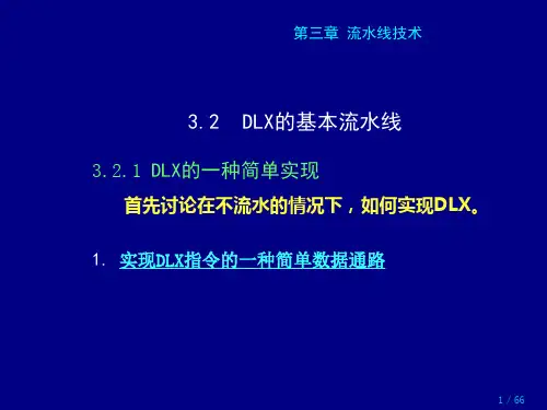
流水线技术--DLX的基本流水线
第一种描述(类似于时空图)
第二种描述(按时间错开的数据通路序列)
虚拟存储器的特点
22/66
3.2 DLX的基本流水线
虚拟存储器的特点
23/66
按时间错开的数据通路序列
虚拟存储器的特点
3.2 DLX的基本流水线
3. 采用流水技术还应解决好以下几个问题:
(1)应保证不会在同一个时钟周期内在同一数据 通路资源上做不同的操作。 例如,不能要求一个ALU同时既做有效 地址计算,又做减法操作。 上述简单DLX流水线中:
ID
EX
EX/MEM.IR ← ID/EX.IR; EX/MEM.ALUOutput ← EX/MEM.ALUOutput ← EX/MEM.IR ← ID/EX.NPC + ID/EX.A op ID/EX.B ID/EX.IR; ID/EX.Imm; 或 EX/MEM.ALUOutput ← EX/MEM.cond ← EX/MEM.ALUOutput ← ID/EX.A + ID/EX.Imm; (ID/EX.A op 0); ID/EX.A op ID/EX.Imm; EX/MEM.cond ← 0; (动画演示) (动画演示) (动画演示)
◆ 流水线各段之间需设置流水线寄存器
(也称为锁存器) ◆ 流水线寄存器组及其所含寄存器的命名 例如,ID段和EX段之间的流水线寄存 器组中的IR寄存器的名称为:ID/EX.IR ◆ 流水线寄存器的作用 把数据和控制信息从一个流水段传 送到下一个流水段。
虚拟存储器的特点 30/66
虚拟存储器的特点
◆ 流水线寄存器的构成
虚拟存储器的特点
17/66
寄存器―寄存器型 ALU 指令 Regs[IR16 ..20] ← ALUOutput
DLX指令集简介
A Neophyte's Guide to DLXThe aim of this file is to provide an introduction to the DLX instruction set, created in Computer Architecture: A Quantitative Approach by Hennessy and Patterson. If you have some programming experience, but only in (relatively) high level languages like C/C++, understanding basic DLX commands and code fragments is well within your realm, despite what you may think after trying to read Hennessy and Patterson's opaque tome. Unfortunately, shining a light through more than a few pages of that monstrosity is beyond the scope of this file, but if you've found Chapter 2 to present some hard slogging, then herein you have found your Mecca.Contents1.What makes up the basic DLX machine?●Registers and Data Types●Addressing Modes●DLX Instruction Format2.DLX Commands: Explanations and Examples● A Few Words on Syntax and Notation●ALU Operations●Data Transfers●Control Commands: Branches and Jumps●Floating Point Operations3.Some Sample Code●Multiply 2*4 and store result●Check array for value zero●Raise a Float to the nth power4.Exercises and Questions for Review●What's Wrong with this code?●Drop a line (or two) - write some code fragments●Things you should know: a partial list●Answers to code exercisesWhat makes up the basic DLX machine?Of course, the machine based on the DLX instruction set is a total work of fiction. If one existed, however, it would be a 32 bit machine, i.e., each word would be four bytes. DLX is Big Endian, as opposed to Little Endian, which means that a DLX address first accesses the byte in the most significant position when it's getting a word out of memory. Another issue, byte alignment, is beyond the scope of this web page, but is something you should probably worry about for exam purposes.Registers and Data TypesThe DLX machine is a general-purpose register (GPR) machine, and as such has at it's core a bunch of registers. The ones you really need to worry about are the integer registers, R0, R1, . . . , R31, the GPRs, and the floating point registers, F0, F1, . . . , F31, the FPRs. Each kind of register holds what you'd expect from the name, with one twist: DLX handles floating point numbers of both "single precision" - 32 bits or four words - and "double precision" -- up to 64 bits, i.e., two words. You know these data types as "doubles" and "floats" from C++. To accommodate double-precision floats, you need to use two consecutive floating point registers, paired together, starting with one that's even-numbered and continuing with one that's odd-numbered. Warning: some operations, notably multiplication and division, can only be performed in the FP registers, even when the operands are integers. Later, we'll see code fragments that move data from integer registers to FP registers, perform the desired operations, and move the data back. (This is a good thing to know how to do because it seems to attract professors looking for exam questions like you-know-what does flies.) To keep things confusing (and to provide more exam fodder), besides the two FP data types, DLX has three integer data types: 8 bit (1 byte), 16 bit (2 byte, or half-word), and 32 bit (4 byte, or word), respectively. The confusing aspect arises when you load less that a word into a register, because you have to worry about the part of the register that doesn't contain the data you just loaded. For example, say you've loaded a word into a register. That word accounts for 8 bits, but the register holds 32 bits. Arithmetic comprehensible to even the dullest moron tells you that you've got another 24 bits floating around out there somewhere in la-la land to worry about. Fortunately, what you do with these left-over bits isn't too difficult, or surprising: you just fill them with 0s. Later, we'll see examples of commands that load data consisting of less than a word into memory. H&P tantalizingly tell you that DLX has a few other "special" registers. These aren't things you'll worry about too much; the one you really need to worry about is the first integer register, R0, because it's value is always 0. What's the purpose of R0? Well, DLX, as you're no doubt aware, is a RISC architecture. (If you didn't know this, you might as well hang up your cleats right here and now.) When H&P (p.98) tell you that "we can use this register to synthesize a variety of useful operations from a simple instruction set" what they mean is that they're going to use a few tricks to fake out some of the commands that DLX doesn't explicitly support. This leads us to our dear friend, R0. Most importantly, while there are a ton of different ways to access memory (that's what all those addressing modes on page 75 are), DLX only explicitly supports one, displacement. As we'll see below, a few of the others are effectively emulated with R0. We'll also see examples of R0's usefulness when we look at jumps and branches (i.e., when implementing a loop one can use R0 as an easy point of reference for a counter). Finally, you should understand that DLX is a (0,3) GPR machine. For exam purposes you undoubtedly need to understand the GPR (m,n) format, and know which machine is which, and why, but for DLX programming purposes all you really need to know is that DLX operations take up to three operands, and that ALU operations and memory accesses cannot be combined. For example, add R3, R2, 256(R1); R3 = R2 + the contents of the memory location pointed to by R1+256 would not work in DLX (although it might in a (1,3) GPR machine). Instead,in DLX, you'd need to do the following: LW R4, 256(R1); load contents of memory location R1+256 into R4 add R3, R2, R4; now we can add: R3 = R2 + R4 As you've probably figured out from the above examples, in DLX, when you're specifying a memory location, you put whatever it is that refers to the memorylocation in parentheses. And in DLX, as the next section explain, the thing in parentheses will always be a register.Addressing ModesThere are three different kinds of objects a CPU may need to access: constants (known in DLX-land as immediates), registers, and memory locations. When H&P are talking about addressing modes, it's easy to forget that they're talking about anything other than a memory location, because we're used to thinking about memory addresses. Thus, it's worth stating the obvious, to wit: that any real computer program will have both constants and will reuse data, and in DLX we have to load data items into registers from memory before we can process them, all of which means that DLX commands address all three kinds of objects. An addressing mode is simply the way in which you describe the object you want to access.What is an addressing mode will probably become most clear when you look at some of the examples below, but for starters consider that, just as you have different modes of address for different people, an instruction set has different addressing modes for different kinds of objects. And just as you might address the same person in a number of different ways, depending on the context of your address (e.g, "Bill", "Mr. President", "hey you", and "Mr. Spineless" can all be used to address the same person) an ISA can use a number of different modes of address to get at the same object. While some cruel 411 instructor may make you know all of them for an exam (see table on page 75), for DLX you need to worry about only five addressing modes, two of which DLX doesn't actually support, but can simulate with our friend R0. DLX's five addressing modes (with the two indirectly supported modes listed last) are as follows::1) Register - this mode you use most of all; it's what you use any time you specify a register. For example, see about any code fragment contained herein, including those in the preceding section, which reference registers. This addressing mode is so basic that H&P don't even bother to mention it as a part of DLX (not that H&P's failure to mention something is a reliable indicator of whether or not it's basic). Remember, any time you access any object, you're using an addressing mode -- just as you are any time you speak to another person.2) Immediate - this is how you access constants. Example:add R2, R1, #3; R2 get sum of contents of R1 and integerThe "#3" is an immediate. The pound sign apparently isn't necessary, but when you see it in H&P in a DLX command, it signifies an immediate.3) Displacement - I would have understood this one better from the start had it been called "offset" mode, because what goes on in the displacement mode is that you specify a register which contains a memory address (e.g., (R1)) and then specify an offset or displacement to be added to the address in the register you've specified. That is, the address you're aiming for is given by the number in the register plus the amount of the displacement you specify. Example:LW R17, 400(R23); put contents of address R23+400 into R174) Register deferred - this address mode is allows you to access a memory address contained ina register. In essence, it's the displacement mode without the displacement. In DLX, you fake this mode by simply using 0 as your offset.Example:LW R17, 0(R23); put contents of address specified by R23 into R175) Absolute - this addressing mode, also known as direct addressing, allows you to specify an address (e.g., (2001)) to be accessed. This one is faked out in DLX by using R0 as your register, and whatever address you want to access as your displacement. Example:LW R17, 2001(R0); put contents of address 2001 into R17DLX Instruction FormatOn page 99 of their monster tome, H&P, with their usual prolixity, describe the format of DLX instructions in a brief paragraph accompanied by a small diagram. There are three formats for DLX instructions: I-type (I is for immediate), R-type (R is for register), and J-type (J is for jump). All DLX instructions are 32 bits long, and commence with a 6 bit opcode. The opcode is simply nothing more than a 6 bit binary number that represents a particular DLX command. For example (and I made this up off the top of my head) suppose the opcode for add is 110011. Then the first six digits of all add instructions will be 110011. Think of a DLX instruction just as you would a programming command in a high-level language. The opcode is like a keyword, and what follows are its arguments. That's what Figure 2.21 on page 99 shows you: what arguments follow the opcode for each type of instruction. For example, the only argument a J-type instruction takes is a 26 bit offset to the PC. This makes sense: when a program branches, what you're doing is skipping to a selected spot in the program, i.e., telling the PC to go next not to the next instruction in the sequence, but the one specified by the offset. Similarly, an I-type instruction takes as arguments two registers, one a target and one an operand, as well as an immediate, the other operand.DLX Commands: Explanations and ExamplesMost of the DLX commands you'll actually need to know (to succeed in CMSC 411, at any rate) are actually pretty easy. The syntax for a DLX command is, in general:<opcode> <target> <source(s)>Specifically, you'll usually use one of the following:<command> <operand register> <immediate><command> <target register> <operand register> <operand register><move command> <target> <source><branch command> <label of place in code to go to>That is, you say what you're going to do, specify which register receives the result, and which registers are accessed to get the result. Obviously, a number of different kinds of commands are described above; don't worry if these descriptions don't make sense to you right off the bat. The four different kinds of instructions in DLX are: (1) ALU operations, (2) data transfers, (3) branches and jumps, and (4) floating point operations. The rest of this section considers each of them in turn, after a brief note on notation.A Few Words on Syntax and NotationAlthough it may not be obvious from the immediately preceding section, DLX syntax, at least insofar as you need to worry about it, is actually pretty simple. Anyone who's ever wrestledwith a header file defining inherited class with pure virtual functions and all that junk in C++ will find mastering the amount of DLX required for this course to be a breeze. The hard part is understanding H&P's complicated and convoluted hardware notation. My advice to you with respect to the hardware notation is that, even though H&P found it so important they put it on the inside back cover of the book, you should ignore it. If you're taking CMSC 411 from the instructor who commissioned this web page, at least, you can follow this advice without any problems. You might need to struggle through a few examples in the book, since their hardware notation is the only commenting that H&P provide, but apart from that, you're better off spending your time worrying about what the code does as opposed to the difficult-to-decipher descriptive scheme concocted by H&P. This web page follows its own advice and ignores H&P's hardware notation. Everything is commented in English. It may be bulkier, but at least you have a shot at comprehending it.ALU OperationsALU operations are at the core of most computer programs. For the most part, they consist of simple arithmetic and simple logic. Arithmetic: Adding, Subtracting, Multiplying and Dividing These are so easy that we include them here only for the sake of completeness. Examples:ADD R3, R2, R1; R3 = R2 + R1SUB R3, R2, R1; R3 = R2 - R1Furthermore, ADDI, ADDU, ADDUI, SUBI, SUBU, and SUBUI all work like the above; simply be aware that the "U" means unsigned and the "I" means immediate, and you should use them as appropriate for your operands (I know at least one CMSC 411 professor who will take points off if you don't!). Multiplication and division work in a fashion similar to add and subtract, save that these operations can only be performed on data contained in floating-point registers. We'll take a look at how to move data from an integer register to a floating point register in the section on data transfers, below.Logic: ANDs, and ORsAND and OR work just like the logical AND and OR you're used to from languages like C++: AND R3, R2, R1; if R1==R2 R3 gets value 1, else R3 gets value 0OR R3, R2, R1; if R2 != 0 or R1 != 0, R3 gets value 1, else R3 gets value 0Other basic logical operations include XOR, ANDI (and immediate), ORI (or immediate), and XORI (xor immediate). They work as you'd expect. Load High ImmediateNow for the twists. The first low-level pain in the rear to worry about is load high immediate:LHI, R19, #429; value 429 goes in upper half of R19, lower half of R19 gets 160sRemember, immediates are 16 bits. If you want to put an immediate in the upper half, i.e., the upper two words, of a memory location, well, then, by gum, LHI is just what you're looking for. And don't worry about the rest of the register -- LHI quite thoughtfully fills the lower two bytes with 0s.ShiftsAnother logical operation that will probably seem familiar from CMSC 311 (remember all those damn shift registers?) is the shift. A shift command takes what's in a register, shifts it to the left or right a specified number of places, and puts the result in the target register, like this:SLL, R6, R5, R3; shift R5 to the left by the amount specified in R3; place value in R6SLLI, R6, R5, #4; shift R5 left 4 places and put result in R6Other shift commands are SRL (shift right logical), SRA (shift right arithmetic), SLLI (shift left logical immediate), SRLI (shift right logical immediate), and SRAI (shift right arithmetic immediate). The arithmetic shifts differ from the logical shifts in that they operate on signed two's-complement numbers to preserve the sign bit upon the shift. (Actually, while this is probably enough to know, it's a little more complicated than this. If, like me, you weren't taught this concept in the prerequisite to CMSC 411, you might want to check out Chapter 9 of Logic and Computer Design Fundamentals by Mano and Kime.)Setting ConditionalsThe category of arithmetic/logical operation we need to worry about are those that set a conditional. DLX allows you to set the following conditions: LT (less than), GT (greater than), LE (less than or equal), GE (greater than or equal), EQ (equal) and NE (not equal). The syntax for setting a condition is:<set condition> <target register> <operand 1> <operand 2>The target register takes on the value of 0 or 1, depending on whether or not comparing the operands meets the established condition. For example:SGE R1, R15, R28; if R15 >= R28 then R1 = 1 else R1 = 0SGEI R1, R27, #1089; if R27 >= 1089 then R1 = 1 else R1 = 0Data TransfersDLX includes three kinds of data transfers: loads, stores, and moves. Loads and StoresLoads and stores are fairly simple, and are essentially the inverse of one another. For example:LW R5, 0(R3); load the word in the memory location pointed to by R3 into R5 SW 0(R3), R5; store the word in R5 in the memory location pointed to by R3 A complete list of load and store commands for integers is as follows: LB (load byte), LBU (load byte unsigned), LH (load half byte), LHU (load half unsigned), LW (load word), SB (store byte), SH (store half), SW (store word). Of course, if you load or store less than a word, that is, a byte or a half, then you have to worry about what happens to the rest of the word. Because DLX is Big Endian, when it works with less than a word it fills the most significant byte(s) of the word, and puts 0s in the rest of the word. For example, loading a byte into a register will put that byte into positions 24-31 of the register, and will put 0s into the register's positions 0-23. Similarly, storing a half word stores two bytes of data in positions 16-31 of the designated memory address, and 0s in positions 0-15. The above commands all act on the integer registers. For floats, you need to know about LF (load float), LD (load double), SF (store float), and SD (store double). These work just like their integer counterparts. Finally, you should make sure you understand the concept of sign extension. No doubt you recall from CMSC 311 that signed two's-complement numbers use their most significant digit for the sign bit. Sign extension simply means that DLX fills empty bits in a word with the sign bit. For example, as H&P describe on page 101, when you use an immediate in an ALU operation, what you get is a 16 bit sign extended immediate - i.e., the upper two bits of the word are filled with the sign bit of the immediate.MovesDLX has three categories of moves: (1) MOVI2S and MOVS2I -- moves between integer registers and special registers, (2) MOVF and MOVD -- copies (not moves) between single precision and double precision FP registers, and (3) MOVFP2I and MOVI2FP -- moves between FP registers and special registers. Notice that almost everywhere else in DLX when you see and "I" it stands for "immediate", but here it means "integer". The syntax for move commands is:<move> <target> <source>It's really that simple. The main issue with moves is remembering to do them when you have data in one register and need to perform an operation that can only be done in another register.Control Commands: Branches and JumpsH&P explain (page 80) that they refer to a " jump when the change in control is unconditional and a branch when the change is conditional." Fair enough, you say, but then you wonder "what's a change in control?" Nothing too complicated it turns out; jumps and branches are just like function calls, ifs, and the like in C++. Of course, when you get to pipelining, jumps and branches are a major headache, but from a pure DLX programming standpoint, you shouldn't find them to be too tough. Ordinarily, in DLX, just like the high level languages it mirrors, instructions are sequentially executed. That is, whenever the CPU gets a new instruction the PC, or program counter, increments by 4 (remember, DLX memory addresses contain four bytes each), and the CPU fetches, decodes, executes, etc. the next instruction in the sequence. A branch mucks up this neat little scheme - just how badly you'll learn when you get to pipelining. For the moment, you need to understand that, when a jump or branch occurs, the program breaks out of its sequential execution, and goes to the instruction named by the branch or jump. In the case of a branch, the sequential execution is broken only if the condition on which the branch is predicated is met. As we explained when we looked at the DLX instruction format, J-type instructions - jumps and branches - have a 26 bit offset which is added to the PC. This offset contains the address of the instruction which should be fetched next in place of the instruction which would otherwise come next in the sequence. From a DLX programming standpoint, this means that whenever you implement a jump or a branch, you include in your command the name of the jump's or the branch's destination. Examples of all the control commands you need to know should make this more clear:BEQZ, R12, subroutine; if R12 == 0 go to line labeled "subroutine"BNEZ, R12, subroutine; if R12 != 0 go to line labeled "subroutine"Branch if equal zero and branch if not equal to zero are more or less self explanatory. So is the basic jump. A jump and link is a little more complicated, but not much. With this command, execution jumps to the line you specify, but the location of the next instruction in the sequence (PC + 4) is stored in R31. Similarly, with jump register and jump and link register, you specify the register to jump to, and, if you also specify a link, PC + 4 is again stored in R31.J loop; go to line labeled "loop"JAL loop; go to line labeled "loop" and put PC + 4 in R31JALR R21; jump to instruction whose address is in R21 and put PC + 4 in R31JR R15; jump to register whose address is R15.DLX also has two commands which test the vlaue of the FP status register. This register is another one of those special registers (like R0 or the PC) whose existence we mentioned earlier.This register, true to its name, reflects the status of floating point operations. Naturally, we want a way to get at that valuable information about how the old FP operations are coming along. That's where BFPT (branch floating point true) and BFPF (branch floating point false) come in. DLX has two other control commands: RFE (return from exception) and TRAP (transfer to operating system). All you need to pretend you know is that they do what you'd think from hearing their names, and beyond that we'll not go here.Floating-point OperationsThe main fact that should concern you with respect to floating point operations is their existence. That is, be aware that when you're dealing with the FP registers, you need to use the commands that manipulate data in those registers. If you want to add two floats, use ADDD (add double) or ADDF (add single-precision float). Likewise for subtracting, multiplying, and dividing. And of course, as we've already noted, you must use the float registers to multiply and divide, even if your operands are integers. Note also that there are special commands for comparing floats just as there are for integers (and they are all analogous). Finally, there are a host of commands to allow you to convert between floats, doubles, and integers. I never used them in CMSC 411 and I don't see why you should either.Some Sample CodeHere are a few simple sample snippets of DLX code to get you started. A few more sample snippets can be found in the answers to the exercises below; these answers aren't commented, so you'll need to look at the code-writing exercises to see what these snippets are supposed to do. Actually, you can probably find all the sample code you need on old exams, but just in case you can't, here goes:Multiply 2*4 and store resultHere we place 4 and 2 in two integer registers, move them to FP registers so we can multiply them, and then move the result back to an integer register so we can store it as an integer. Note that, since we're creating what's in the integer registers by adding immediates, we could have simply added the immediates to the FP registers. Such an implementation of our multiplication would have created a pedagogical shortfall, however, because we would have lost an opportunity to display our moves.ADDI R1, R0, #4; R1 now contains 4ADDI R2, R0, #2; R2 now contains 2MOVI2FP F1, R1; contents of R1 (the value 4) moved to F1MOVI2FP F2, R2; contents of R2 (the value 2) moved to F2MULT F3, F2, F1; F3 now contains 8 (2*4)MOVFP2I R3, F3; contents of F3 (the value 8) moved to R3SW 7000(R0), R3; integer 8 stored in memory location 7000Check array for value zeroHere's a loop for you. This code fragment checks the elements of a 10 element array for the value 0, stopping when the value is found, or when all 10 elements have been checked. If a zero is found, the code stores a non-zero value (signifying "true"), else it stores a 0 (signifying "false"). Kind of confusing, eh? This truly is a code fragment in the proud spirit of H&P!ADDI R31, R0, #1 ; R31 = 9loop: LW R15, 0(R1); put integer in location R1 into R15BEQZ R15, done; if R15 == 0 we need to exit the loop nowADDI R1, R1, #4; make R1 point to the next element in the arraySUBI R31, R31, #1; decrement R31 by 1BNEZ R15, loop; if R15 != 0, we need to check the next valuedone: SW 256(R0), R31; R31 == 0 only if we FAILED to find a 0 in the arrayRaise a float to the nth powerHere's another loop. Assume we have a float, X, in F1, and a positive integer, I, in R1. We want to raise X to the Ith power.ADDI R2, R0, #1; R2 = 1MOVI2FP F3, R2; F3 = 1loop: MULT F3, F3, F1; F3 = F3*F1SUBI, R1, R1, #1; decrement R1 by 1BNEZ, R1, loop; if R1 != 0 then we need to continueSW 3000(R0), F3; store resultExercises and Questions for ReviewThe following problems are here more to test your knowledge than to challenge you. The point is that if you get somewhat comfortable with DLX, issues you may be tested on won't present any more difficulty than programming problems presented in any of the languages you've already worked in.What's wrong with this code?Figure out what's wrong with the following lines of code:ADDI R34, R5, R0;LW 0(R12), F23;SUB 0(R26), F4, R3;J R11;MULT R9, R8, R7;LD F15, 0(R1);Drop a line (or two)Write a line or two of code that does the following:Tests to see if a value in R19 is equal to zero, and branches to a line labeled "loop" if it is not.Jumps to an instruction who's pointed to by R16, and saves the address of the next instruction (PC+4) in R31. Multiplies two integers residing in R1 and R2 and stores the result. Load two double precision floats, multiply them, and store the result. Find the factorial of the number 10 and store the result. Since there is always more than one way to skin a cat, your answers may be different - but not too different, because the code here is all very short and simple - from the answers below and still right.Things you should know: a partial listHere are a few concepts related to DLX with which you should be conversant. Each term is a link to the place in this web page where we explain it.Addressing modes (can you name and describe all the kinds DLX uses?)Big EndianDisplacementDLX data typesDLX instruction formatsImmediateLoad high immediateopcodeSign extensionAnswersHere are answers to some of the review questions:What's wrong with this code? Let's have a look . . .First, the GPRs range from R0 to R31; there's no R34. Secondly, ADDI means you're adding an immediate, and R0, though a special register (remember, it's always 0), is not an immediate.DLX syntax always puts the target before the source (and the cart before the horse). The register holding the address of the word to be loaded should come after the target register is specified.DLX is a (0,3) architecture; you can't put a memory reference in an ALU command. Also, what's that FPR doing in there?J, a plain old jump command takes the name of the line of code (e.g., "loop" or "subroutine1") as its argument; if you want to specify an address in a register for the jump target, use JR.MULT only works on data in FPRs.You can only load a double into an even numbered FPR; for doubles, FPRs travel in pairs (see the section above on registers).Drop a Line (or two) - here's what you shoulda coulda dropped . . .。
DLX指令集简介
A Neophyte's Guide to DLXThe aim of this file is to provide an introduction to the DLX instruction set,created in Computer Architecture:A Quantitative Approach by Hennessy and Patterson.If you have some programming experience,but only in(relatively)high level languages like C/C++,understanding basic DLX commands and code fragments is well within your realm,despite what you may think after trying to read Hennessy and Patterson's opaque tome.Unfortunately,shining a light through more than a few pages of that monstrosity is beyond the scope of this file,but if you've found Chapter2to present some hard slogging,then herein you have found your Mecca.Contents1.What makes up the basic DLX machine?●Registers and Data Types●Addressing Modes●DLX Instruction Format2.DLX Commands:Explanations and Examples●A Few Words on Syntax and Notation●ALU Operations●Data Transfers●Control Commands:Branches and Jumps●Floating Point Operations3.Some Sample Code●Multiply2*4and store result●Check array for value zero●Raise a Float to the nth power4.Exercises and Questions for Review●What's Wrong with this code?●Drop a line(or two)-write some code fragments●Things you should know:a partial list●Answers to code exercisesWhat makes up the basic DLX machine?Of course,the machine based on the DLX instruction set is a total work of fiction.If one existed, however,it would be a32bit machine,i.e.,each word would be four bytes.DLX is Big Endian, as opposed to Little Endian,which means that a DLX address first accesses the byte in the most significant position when it's getting a word out of memory.Another issue,byte alignment,is beyond the scope of this web page,but is something you should probably worry about for exam purposes.Registers and Data TypesThe DLX machine is a general-purpose register(GPR)machine,and as such has at it's core a bunch of registers.The ones you really need to worry about are the integer registers,R0,R1,..., R31,the GPRs,and the floating point registers,F0,F1,...,F31,the FPRs.Each kind of register holds what you'd expect from the name,with one twist:DLX handles floating point numbers of both"single precision"-32bits or four words-and"double precision"--up to64bits,i.e.,two words.You know these data types as"doubles"and"floats"from C++.To accommodate double-precision floats,you need to use two consecutive floating point registers,paired together, starting with one that's even-numbered and continuing with one that's odd-numbered.Warning: some operations,notably multiplication and division,can only be performed in the FP registers, even when the operands are ter,we'll see code fragments that move data from integer registers to FP registers,perform the desired operations,and move the data back.(This is a good thing to know how to do because it seems to attract professors looking for exam questions like you-know-what does flies.)To keep things confusing(and to provide more exam fodder),besides the two FP data types,DLX has three integer data types:8bit(1byte),16bit(2byte,or half-word),and32bit(4byte,or word),respectively.The confusing aspect arises when you load less that a word into a register,because you have to worry about the part of the register that doesn't contain the data you just loaded.For example,say you've loaded a word into a register.That word accounts for8bits,but the register holds32bits.Arithmetic comprehensible to even the dullest moron tells you that you've got another24bits floating around out there somewhere in la-la land to worry about.Fortunately,what you do with these left-over bits isn't too difficult,or surprising: you just fill them ter,we'll see examples of commands that load data consisting of less than a word into memory.H&P tantalizingly tell you that DLX has a few other"special"registers. These aren't things you'll worry about too much;the one you really need to worry about is the first integer register,R0,because it's value is always0.What's the purpose of R0?Well,DLX,as you're no doubt aware,is a RISC architecture.(If you didn't know this,you might as well hang up your cleats right here and now.)When H&P(p.98)tell you that"we can use this register to synthesize a variety of useful operations from a simple instruction set"what they mean is that they're going to use a few tricks to fake out some of the commands that DLX doesn't explicitly support.This leads us to our dear friend,R0.Most importantly,while there are a ton of different ways to access memory(that's what all those addressing modes on page75are),DLX only explicitly supports one,displacement.As we'll see below,a few of the others are effectively emulated with R0.We'll also see examples of R0's usefulness when we look at jumps and branches(i.e.,when implementing a loop one can use R0as an easy point of reference for a counter).Finally,you should understand that DLX is a(0,3)GPR machine.For exam purposes you undoubtedly need to understand the GPR(m,n)format,and know which machine is which,and why,but for DLX programming purposes all you really need to know is that DLX operations take up to three operands,and that ALU operations and memory accesses cannot be combined.For example,add R3,R2,256(R1);R3=R2+the contents of the memory location pointed to by R1+256would not work in DLX(although it might in a(1,3)GPR machine).Instead,in DLX,you'd need to do the following:LW R4,256(R1);load contents of memory location R1+256into R4add R3,R2,R4; now we can add:R3=R2+R4As you've probably figured out from the above examples,in DLX, when you're specifying a memory location,you put whatever it is that refers to the memorylocation in parentheses.And in DLX,as the next section explain,the thing in parentheses will always be a register.Addressing ModesThere are three different kinds of objects a CPU may need to access:constants(known in DLX-land as immediates),registers,and memory locations.When H&P are talking about addressing modes,it's easy to forget that they're talking about anything other than a memory location,because we're used to thinking about memory addresses.Thus,it's worth stating the obvious,to wit:that any real computer program will have both constants and will reuse data,and in DLX we have to load data items into registers from memory before we can process them,all of which means that DLX commands address all three kinds of objects.An addressing mode is simply the way in which you describe the object you want to access.What is an addressing mode will probably become most clear when you look at some of the examples below,but for starters consider that,just as you have different modes of address for different people,an instruction set has different addressing modes for different kinds of objects. And just as you might address the same person in a number of different ways,depending on the context of your address(e.g,"Bill","Mr.President","hey you",and"Mr.Spineless"can all be used to address the same person)an ISA can use a number of different modes of address to get at the same object.While some cruel411instructor may make you know all of them for an exam (see table on page75),for DLX you need to worry about only five addressing modes,two of which DLX doesn't actually support,but can simulate with our friend R0.DLX's five addressing modes(with the two indirectly supported modes listed last)are as follows::1)Register-this mode you use most of all;it's what you use any time you specify a register. For example,see about any code fragment contained herein,including those in the preceding section,which reference registers.This addressing mode is so basic that H&P don't even bother to mention it as a part of DLX(not that H&P's failure to mention something is a reliable indicator of whether or not it's basic).Remember,any time you access any object,you're using an addressing mode--just as you are any time you speak to another person.2)Immediate-this is how you access constants.Example:add R2,R1,#3;R2get sum of contents of R1and integerThe"#3"is an immediate.The pound sign apparently isn't necessary,but when you see it in H&P in a DLX command,it signifies an immediate.3)Displacement-I would have understood this one better from the start had it been called "offset"mode,because what goes on in the displacement mode is that you specify a register which contains a memory address(e.g.,(R1))and then specify an offset or displacement to be added to the address in the register you've specified.That is,the address you're aiming for is given by the number in the register plus the amount of the displacement you specify.Example:LW R17,400(R23);put contents of address R23+400into R174)Register deferred-this address mode is allows you to access a memory address contained ina register.In essence,it's the displacement mode without the displacement.In DLX,you fake this mode by simply using0as your offset.Example:LW R17,0(R23);put contents of address specified by R23into R175)Absolute-this addressing mode,also known as direct addressing,allows you to specify an address(e.g.,(2001))to be accessed.This one is faked out in DLX by using R0as your register, and whatever address you want to access as your displacement.Example:LW R17,2001(R0);put contents of address2001into R17DLX Instruction FormatOn page99of their monster tome,H&P,with their usual prolixity,describe the format of DLX instructions in a brief paragraph accompanied by a small diagram.There are three formats for DLX instructions:I-type(I is for immediate),R-type(R is for register),and J-type(J is for jump). All DLX instructions are32bits long,and commence with a6bit opcode.The opcode is simply nothing more than a6bit binary number that represents a particular DLX command.For example (and I made this up off the top of my head)suppose the opcode for add is110011.Then the first six digits of all add instructions will be110011.Think of a DLX instruction just as you would a programming command in a high-level language.The opcode is like a keyword,and what follows are its arguments.That's what Figure2.21on page99shows you:what arguments follow the opcode for each type of instruction.For example,the only argument a J-type instruction takes is a 26bit offset to the PC.This makes sense:when a program branches,what you're doing is skipping to a selected spot in the program,i.e.,telling the PC to go next not to the next instruction in the sequence,but the one specified by the offset.Similarly,an I-type instruction takes as arguments two registers,one a target and one an operand,as well as an immediate,the other operand.DLX Commands:Explanations and ExamplesMost of the DLX commands you'll actually need to know(to succeed in CMSC411,at any rate)are actually pretty easy.The syntax for a DLX command is,in general:<opcode><target><source(s)>Specifically,you'll usually use one of the following:<command><operand register><immediate><command><target register><operand register><operand register><move command><target><source><branch command><label of place in code to go to>That is,you say what you're going to do,specify which register receives the result,and which registers are accessed to get the result.Obviously,a number of different kinds of commands are described above;don't worry if these descriptions don't make sense to you right off the bat.The four different kinds of instructions in DLX are:(1)ALU operations,(2)data transfers,(3) branches and jumps,and(4)floating point operations.The rest of this section considers each of them in turn,after a brief note on notation.A Few Words on Syntax and NotationAlthough it may not be obvious from the immediately preceding section,DLX syntax,at least insofar as you need to worry about it,is actually pretty simple.Anyone who's ever wrestledwith a header file defining inherited class with pure virtual functions and all that junk in C++will find mastering the amount of DLX required for this course to be a breeze.The hard part is understanding H&P's complicated and convoluted hardware notation.My advice to you with respect to the hardware notation is that,even though H&P found it so important they put it on the inside back cover of the book,you should ignore it.If you're taking CMSC411from the instructor who commissioned this web page,at least,you can follow this advice without any problems.You might need to struggle through a few examples in the book,since their hardware notation is the only commenting that H&P provide,but apart from that,you're better off spending your time worrying about what the code does as opposed to the difficult-to-decipher descriptive scheme concocted by H&P.This web page follows its own advice and ignores H&P's hardware notation. Everything is commented in English.It may be bulkier,but at least you have a shot at comprehending it.ALU OperationsALU operations are at the core of most computer programs.For the most part,they consist of simple arithmetic and simple logic.Arithmetic:Adding,Subtracting,Multiplying and Dividing These are so easy that we include them here only for the sake of completeness.Examples:ADD R3,R2,R1;R3=R2+R1SUB R3,R2,R1;R3=R2-R1Furthermore,ADDI,ADDU,ADDUI,SUBI,SUBU,and SUBUI all work like the above; simply be aware that the"U"means unsigned and the"I"means immediate,and you should use them as appropriate for your operands(I know at least one CMSC411professor who will take points off if you don't!).Multiplication and division work in a fashion similar to add and subtract, save that these operations can only be performed on data contained in floating-point registers. We'll take a look at how to move data from an integer register to a floating point register in the section on data transfers,below.Logic:ANDs,and ORsAND and OR work just like the logical AND and OR you're used to from languages like C++: AND R3,R2,R1;if R1==R2R3gets value1,else R3gets value0OR R3,R2,R1;if R2!=0or R1!=0,R3gets value1,else R3gets value0Other basic logical operations include XOR,ANDI(and immediate),ORI(or immediate),and XORI(xor immediate).They work as you'd expect.Load High ImmediateNow for the twists.The first low-level pain in the rear to worry about is load high immediate:LHI,R19,#429;value429goes in upper half of R19,lower half of R19gets160sRemember,immediates are16bits.If you want to put an immediate in the upper half,i.e.,the upper two words,of a memory location,well,then,by gum,LHI is just what you're looking for. And don't worry about the rest of the register--LHI quite thoughtfully fills the lower two bytes with0s.ShiftsAnother logical operation that will probably seem familiar from CMSC311(remember all those damn shift registers?)is the shift.A shift command takes what's in a register,shifts it to the left or right a specified number of places,and puts the result in the target register,like this:SLL,R6,R5,R3;shift R5to the left by the amount specified in R3;place value in R6SLLI,R6,R5,#4;shift R5left4places and put result in R6Other shift commands are SRL(shift right logical),SRA(shift right arithmetic),SLLI(shift left logical immediate),SRLI(shift right logical immediate),and SRAI(shift right arithmetic immediate).The arithmetic shifts differ from the logical shifts in that they operate on signed two's-complement numbers to preserve the sign bit upon the shift.(Actually,while this is probably enough to know,it's a little more complicated than this.If,like me,you weren't taught this concept in the prerequisite to CMSC411,you might want to check out Chapter9of Logic and Computer Design Fundamentals by Mano and Kime.)Setting ConditionalsThe category of arithmetic/logical operation we need to worry about are those that set a conditional.DLX allows you to set the following conditions:LT(less than),GT(greater than),LE (less than or equal),GE(greater than or equal),EQ(equal)and NE(not equal).The syntax for setting a condition is:<set condition><target register><operand1><operand2>The target register takes on the value of0or1,depending on whether or not comparing the operands meets the established condition.For example:SGE R1,R15,R28;if R15>=R28then R1=1else R1=0SGEI R1,R27,#1089;if R27>=1089then R1=1else R1=0Data TransfersDLX includes three kinds of data transfers:loads,stores,and moves.Loads and StoresLoads and stores are fairly simple,and are essentially the inverse of one another.For example:LW R5,0(R3);load the word in the memory location pointed to by R3into R5SW0(R3),R5; store the word in R5in the memory location pointed to by R3A complete list of load and store commands for integers is as follows:LB(load byte),LBU(load byte unsigned),LH(load half byte),LHU(load half unsigned),LW(load word),SB(store byte),SH(store half),SW(store word).Of course,if you load or store less than a word,that is,a byte or a half,then you have to worry about what happens to the rest of the word.Because DLX is Big Endian,when it works with less than a word it fills the most significant byte(s)of the word,and puts0s in the rest of the word.For example,loading a byte into a register will put that byte into positions24-31of the register,and will put0s into the register's positions0-23.Similarly,storing a half word stores two bytes of data in positions16-31of the designated memory address,and0s in positions0-15.The above commands all act on the integer registers.For floats,you need to know about LF(load float),LD(load double),SF(store float),and SD(store double).These work just like their integer counterparts.Finally,you should make sure you understand the concept of sign extension.No doubt you recall from CMSC311that signed two's-complement numbers use their most significant digit for the sign bit.Sign extension simply means that DLX fills empty bits in a word with the sign bit.For example,as H&P describe on page101,when you use an immediate in an ALU operation,what you get is a16bit sign extended immediate-i.e.,the upper two bits of the word are filled with the sign bit of the immediate.MovesDLX has three categories of moves:(1)MOVI2S and MOVS2I--moves between integer registers and special registers,(2)MOVF and MOVD--copies(not moves)between single precision and double precision FP registers,and(3)MOVFP2I and MOVI2FP--moves between FP registers and special registers.Notice that almost everywhere else in DLX when you see and "I"it stands for"immediate",but here it means"integer".The syntax for move commands is:<move><target><source>It's really that simple.The main issue with moves is remembering to do them when you have data in one register and need to perform an operation that can only be done in another register.Control Commands:Branches and JumpsH&P explain(page80)that they refer to a"jump when the change in control is unconditional and a branch when the change is conditional."Fair enough,you say,but then you wonder"what's a change in control?"Nothing too complicated it turns out;jumps and branches are just like function calls,ifs,and the like in C++.Of course,when you get to pipelining,jumps and branches are a major headache,but from a pure DLX programming standpoint,you shouldn't find them to be too tough.Ordinarily,in DLX,just like the high level languages it mirrors, instructions are sequentially executed.That is,whenever the CPU gets a new instruction the PC, or program counter,increments by4(remember,DLX memory addresses contain four bytes each), and the CPU fetches,decodes,executes,etc.the next instruction in the sequence.A branch mucks up this neat little scheme-just how badly you'll learn when you get to pipelining.For the moment, you need to understand that,when a jump or branch occurs,the program breaks out of its sequential execution,and goes to the instruction named by the branch or jump.In the case of a branch,the sequential execution is broken only if the condition on which the branch is predicated is met.As we explained when we looked at the DLX instruction format,J-type instructions-jumps and branches-have a26bit offset which is added to the PC.This offset contains the address of the instruction which should be fetched next in place of the instruction which would otherwise come next in the sequence.From a DLX programming standpoint,this means that whenever you implement a jump or a branch,you include in your command the name of the jump's or the branch's destination.Examples of all the control commands you need to know should make this more clear:BEQZ,R12,subroutine;if R12==0go to line labeled"subroutine"BNEZ,R12,subroutine;if R12!=0go to line labeled"subroutine"Branch if equal zero and branch if not equal to zero are more or less self explanatory.So is the basic jump.A jump and link is a little more complicated,but not much.With this command, execution jumps to the line you specify,but the location of the next instruction in the sequence (PC+4)is stored in R31.Similarly,with jump register and jump and link register,you specify the register to jump to,and,if you also specify a link,PC+4is again stored in R31.J loop;go to line labeled"loop"JAL loop;go to line labeled"loop"and put PC+4in R31JALR R21;jump to instruction whose address is in R21and put PC+4in R31JR R15;jump to register whose address is R15.DLX also has two commands which test the vlaue of the FP status register.This register is another one of those special registers(like R0or the PC)whose existence we mentioned earlier.This register,true to its name,reflects the status of floating point operations.Naturally,we want a way to get at that valuable information about how the old FP operations are coming along.That's where BFPT(branch floating point true)and BFPF(branch floating point false)come in.DLX has two other control commands:RFE(return from exception)and TRAP(transfer to operating system).All you need to pretend you know is that they do what you'd think from hearing their names,and beyond that we'll not go here.Floating-point OperationsThe main fact that should concern you with respect to floating point operations is their existence.That is,be aware that when you're dealing with the FP registers,you need to use the commands that manipulate data in those registers.If you want to add two floats,use ADDD(add double)or ADDF(add single-precision float).Likewise for subtracting,multiplying,and dividing. And of course,as we've already noted,you must use the float registers to multiply and divide, even if your operands are integers.Note also that there are special commands for comparing floats just as there are for integers(and they are all analogous).Finally,there are a host of commands to allow you to convert between floats,doubles,and integers.I never used them in CMSC411and I don't see why you should either.Some Sample CodeHere are a few simple sample snippets of DLX code to get you started.A few more sample snippets can be found in the answers to the exercises below;these answers aren't commented,so you'll need to look at the code-writing exercises to see what these snippets are supposed to do. Actually,you can probably find all the sample code you need on old exams,but just in case you can't,here goes:Multiply2*4and store resultHere we place4and2in two integer registers,move them to FP registers so we can multiply them,and then move the result back to an integer register so we can store it as an integer.Note that,since we're creating what's in the integer registers by adding immediates,we could have simply added the immediates to the FP registers.Such an implementation of our multiplication would have created a pedagogical shortfall,however,because we would have lost an opportunity to display our moves.ADDI R1,R0,#4;R1now contains4ADDI R2,R0,#2;R2now contains2MOVI2FP F1,R1;contents of R1(the value4)moved to F1MOVI2FP F2,R2;contents of R2(the value2)moved to F2MULT F3,F2,F1;F3now contains8(2*4)MOVFP2I R3,F3;contents of F3(the value8)moved to R3SW7000(R0),R3;integer8stored in memory location7000Check array for value zeroHere's a loop for you.This code fragment checks the elements of a10element array for the value0,stopping when the value is found,or when all10elements have been checked.If a zero is found,the code stores a non-zero value(signifying"true"),else it stores a0(signifying"false"). Kind of confusing,eh?This truly is a code fragment in the proud spirit of H&P!ADDI R31,R0,#1;R31=9loop:LW R15,0(R1);put integer in location R1into R15BEQZ R15,done;if R15==0we need to exit the loop nowADDI R1,R1,#4;make R1point to the next element in the arraySUBI R31,R31,#1;decrement R31by1BNEZ R15,loop;if R15!=0,we need to check the next valuedone:SW256(R0),R31;R31==0only if we FAILED to find a0in the arrayRaise a float to the nth powerHere's another loop.Assume we have a float,X,in F1,and a positive integer,I,in R1.We want to raise X to the Ith power.ADDI R2,R0,#1;R2=1MOVI2FP F3,R2;F3=1loop:MULT F3,F3,F1;F3=F3*F1SUBI,R1,R1,#1;decrement R1by1BNEZ,R1,loop;if R1!=0then we need to continueSW3000(R0),F3;store resultExercises and Questions for ReviewThe following problems are here more to test your knowledge than to challenge you.The point is that if you get somewhat comfortable with DLX,issues you may be tested on won't present any more difficulty than programming problems presented in any of the languages you've already worked in.What's wrong with this code?Figure out what's wrong with the following lines of code:ADDI R34,R5,R0;LW0(R12),F23;SUB0(R26),F4,R3;J R11;MULT R9,R8,R7;LD F15,0(R1);Drop a line(or two)Write a line or two of code that does the following:Tests to see if a value in R19is equal to zero,and branches to a line labeled"loop"if it is not.Jumps to an instruction who's pointed to by R16,and saves the address of the next instruction (PC+4)in R31.Multiplies two integers residing in R1and R2and stores the result.Load two double precision floats,multiply them,and store the result.Find the factorial of the number10and store the result.Since there is always more than one way to skin a cat,your answers may be different-but not too different,because the code here is all very short and simple -from the answers below and still right.Things you should know:a partial listHere are a few concepts related to DLX with which you should be conversant.Each term is a link to the place in this web page where we explain it.Addressing modes(can you name and describe all the kinds DLX uses?)Big EndianDisplacementDLX data typesDLX instruction formatsImmediateLoad high immediateopcodeSign extensionAnswersHere are answers to some of the review questions:What's wrong with this code?Let's have a look...First,the GPRs range from R0to R31;there's no R34.Secondly,ADDI means you're adding an immediate,and R0,though a special register(remember,it's always0),is not an immediate.DLX syntax always puts the target before the source(and the cart before the horse).The register holding the address of the word to be loaded should come after the target register is specified.DLX is a(0,3)architecture;you can't put a memory reference in an ALU command.Also, what's that FPR doing in there?J,a plain old jump command takes the name of the line of code(e.g.,"loop"or "subroutine1")as its argument;if you want to specify an address in a register for the jump target,use JR.MULT only works on data in FPRs.You can only load a double into an even numbered FPR;for doubles,FPRs travel in pairs (see the section above on registers).Drop a Line(or two)-here's what you shoulda coulda dropped...。
熟悉WINDDLX使用
试验一熟悉WinDLX的使用
一、实验目的
1.熟练掌握WinDLX处理器的操作和使用
2.熟悉DLX指令集结构及其特点
二、实验内容
1.利用WinLX处理器执行求阶程序 fact.s这个程序说明浮点指
令的使用。
该程序从标准输入读入一个整数,求其阶乘,然后将结果输出。
该程序中调用了input.s中的输入子程序,这个子程序用于读入正整数。
2.利用WinDLX处理器执行求最大公约数程序gcm.s。
该程序从标准输
入读入两个整数,求它们的最大公约数,然后将结果写到标准输出。
该程序中调用了input.s中的输入子程序
3.通过上述使用 WinDLX,总结WinDLX的特点。
三、实验数据及显示结果
1.求5的阶乘
2.求15和12的最大公约数。
DLX机器
SR1
SR2
Imm16
Imm16
DR
未用
001101
SLLI
001101
SR1
DR
Imm16
SRL
000000
SR1
SR2
DR
未用
001110
SRLI
001110
SR1
DR
Imm16
SRA
000000
SR1
SR2
DR
未用001111Fra bibliotekSRAI
001111
SR1
DR
Imm16
SLT
000000
SR1
SR2
ADDI
R4
R1
14
ADD代表加,I代表立即数(Immediate)
第一个操作数R4 第二个源操作数在指令中
[15:0]位符号扩展(SEXT)
目标操作数写入R1
寄存器堆 R0 0000 0000 0000 0000 0000 0000 0000 0000 0 R1 …… R2 R3 R4 0000 0000 0000 0000 0000 0000 0000 0110 6
MIPS
DLX指令
32位 从左向右依次编号,31、30、……0
符号[l:r]
位组合的子单元 字段
指令格式
I-类型
31
26 25
21 20
16 15
0
操作码
SR1
DR
Imm16
R-类型
J-类型
31
26 25
21 20
16 15
11 10
操作码
SR1
SR2
DR
未用
DLX指令集结构
或 和立即值或
异或 和立即值异或
载入高位立即值
包含了立即值(S_I)和变量(S_)的移位操作 移位有:逻辑左移,逻辑右移和算术右移
设置条件 “_”可以是 LT、GT、LE、GE、EQ、、NE
指令类型 控制
操作码 BEQZ BNEZ
BFPT BFPF
J JR
JAL JALR
TRAP
RFE
SUB SUBI SUBU SUBUI
MULT MULTU
DIV DIVU
AND ANDI
OR ORI XOR XORI
LHI
SLL SRL SRA SLLI SRLI SRAI
S_ S_I
含义 带符号加 带符号立即值加 无符号加 无符号立即值加
带符号减 带符号立即值减
无符号减 无符号立即值减
带符号乘 无符号乘 带符号除 无符号除
含义 根存器中的比较位为真/假进行分 支
跳转 基于寄存器的跳转
跳转并链接 基于寄存器的跳转并链接
转换到操作系统
从异常恢复用户模式
指令类型 浮点
操作码
ADDD ADDF
SUBD SUBF
MULTD MULTF
DIVD DIVF
CVTF2D CVTF2I CVTD2F CVTD2I CVTI2F CVTI2D
将通用寄存器中的内容移入特殊寄存器 将特殊寄存器中的内容移入通用寄存器
将一个单精度/双精度浮点寄存器的内容拷贝到 另一个单精度/双精度浮点寄存器
将 32 位浮点寄存器中的内容移入整型寄存器 将 32 位整型寄存器中的内容移入浮点寄存器
指令类型 算数/逻辑
操作码
ADD ADDI ADDU ADDUI
试验一 熟悉WInDLX的使用
实验一熟悉WInDLX的使用实验目的:通过本实验,熟练掌握WinDLX模拟器的操作和使用,熟悉DLX指令集结构及其特点。
实验内容:一.用WinDLX模拟器执行求阶乘程序facts 。
执行步骤详见“WinDLX 教程”。
这个程序说明浮点指令的使用。
该程序从标准输入读入一个整数,求其阶乘,然后将结果输出。
该程序中调用了input.s中的输入子程序,这个子程序用于读入正整数。
二.输入数据“3”采用单步执行方法,完成程序并通过上述使用WinDLX,总结WinDLX的特点。
三.意观察变量说明语句所建立的数据区,理解WinDLX指令系统。
实验步骤:一.运行WinDLX仿真器。
二.在开始模拟之前,fact.s程序装入一个程序到主存。
在装入fact.s程序的同时需要同时装入input.s程序,现在可以开始模拟工作了。
三.找出实验中的不明白的地方,自己解决并写出原因。
四.输入数据“3”采用单步执行方法,完成程序并通过上述使用WinDLX,总结WinDLX的特点。
实验结果:打开Pipeline窗口,点击 F7用单步执行,做完以后,用多步执行命令,实验结果如下所示:用F7单步跟踪直到出现如下所示:输入“3”然后“确定”。
结果如下所示:在本次实验遇到两个问题:问题一在上述窗口中,你将看到模拟正在第四时钟周期,第一条命令正在MEM 段,第二条命令在intEX段,第四条命令在IF段。
而第三条命令指示为"aborted"。
其原因是:第二条命令(jal)是无条件分支指令,但只有在第三个时钟周期,jal指令被译码后才知道,这时,下一条命令movi2fp已经取出,但需执行的下一条命令在另一个地址处,因而,movi2fp的执行应被取消,在流水线中留下气泡。
问题二在下图中,你将看到模拟正处于时钟周期14。
trap 0x5行如下所示:原因是:无论何时遇到一条trap指令时,DLX 处理器中的流水线将被清空实验体会:通过本次实验我掌握了WinDLX模拟器的操作和使用,了解DLX指令集结构及其特点,更加深入的了解计算机系统流水线的工作过程。
- 1、下载文档前请自行甄别文档内容的完整性,平台不提供额外的编辑、内容补充、找答案等附加服务。
- 2、"仅部分预览"的文档,不可在线预览部分如存在完整性等问题,可反馈申请退款(可完整预览的文档不适用该条件!)。
- 3、如文档侵犯您的权益,请联系客服反馈,我们会尽快为您处理(人工客服工作时间:9:00-18:30)。
0.1%
8.3% 1.3%
12.4% 6.8%
li 31.3% 16.7% 11.1%
5.4% 2.4%
整型平均 26% 9% 14% 0% 0% 0% 13% 3%
21/29
指令
compress eqntott Espresso gcc(cc1)
条件分支
17.4%
24.0%
15.0%
11.5%
无条件分支
含义 载入字节,载入无符号字节,储存字节
LH,LHU,SH
载入半字,载入无符号半字,储存半字
LW,SW
载入字,储存字
LF,LD,SF,SD MOVI2S,MOVS2I MOVF,MOVD MOVFP2I,MOVI2FP
载入单精度浮点,载入双精度浮点,储存单 精度浮点,储存双精度浮点
将通用寄存器中的内容移入特殊寄存器,将 特殊寄存器中的内容移入通用寄存器
2/29
◆ 64位双精度浮点数 相邻两个浮点寄存器奇偶对FiFi+1 (i = 0,2,4,,30) 命名: F0、F2、、F28、F30
(3) 一些特殊的寄存器 (比如用来保存浮点操作结果信息的浮点状态寄存器)
可以和通用寄存器相互进行数据传送。
3/29
2. DLX的数据类型 DLX提供了多种长度的整型数据和浮点数据。
(1) 整型数据 有8位、16位和32位多种长度。 (当8位和16位整型数据载入到寄存器中时, 用0或数据的符号位来填充32位通用寄存器 中的剩余位。)
(2) 浮点数据 有32位单精度浮点数和64位双精度浮点数。 浮点数据表示采用的是IEEE 754标准。
4/29
3. DLX的寻址方式和数据传送 (1) 寻址方式 寄存器寻址 立即值寻址 偏移寻址 寄存器间接寻址 (2) 寄存器寻址字段的大小为5位,用来表示32个 通用寄存器或浮点寄存器。 (3) 存储器地址采用的是高端字节表示顺序,存 储器按字节寻址,其地址宽度为32位。
11/29
(2) ALU操作
简单的算术和逻辑运算 寄存器比较指令(,,,,,)
ALU指令实例
指令实例
指令名称
含义
Add R1, R2, R3 加
Regs[R1] ← Regs[R2] + Regs[R3]
ADDI R1, R2, #3 和立即值相加
Regs[R1] ← Regs[R2] + 3
JAL name
跳转并链接
JALR R2 JR R3
寄存器型 跳转并链接
寄存器型跳转
PC ← name; ((PC+4)-225) ≤ name ≤((PC+4)+225)
Regs[R31] ← PC+4; PC ← name; ((PC+4)-225) ≤ name ≤((PC+4)+225)
Regs[R31] ← PC+4; PC ← Regs[R2];
(1) Load和Store操作
10/29
指令实例 LW R1, 30 (R2) LW R1, 1000 (R0) LB R1, 40 (R3) LBU R1, 40 (R3) LH R1, 40 (R3)
LF F0, 50 (R3) LD F0, 50 (R2) SW 500 (R4), R3 SF 40 (R3), F0 SD 40 (R3), F0
1.5%
0.9%
0.5%
1.3%
调用
0.1%
0.5%
0.4%
1.1%
返回,跳转
0.1%
0.5%
0.5%
1.5%
移位
6.5%
0.3%
7.0%
6.2%
与
2.1%
0.1%
9.4%
1.6%
或
6.0%
5.5%
4.8%
4.2%
其它(异或, 非)
1.0%
2.0%
0.5%
li 14.6% 1.8% 3.1% 3.5% 0.7% 2.1% 6.2% 0.1%
将一个单精度/双精度浮点寄存器的内容拷贝 到另一个单精度/双精度浮点寄存器
将32位浮点寄存器中的内容移入整型寄存器, 将32位整型寄存器中的内容移入浮点寄存器
17/29
指令 类型
算术 /逻辑
操作码
含义
ADD,ADDI,ADDU,ADD UI
SUB,SUBI,SUBU,SUB UI
MULT,MULTU,DIV,DIV U
(4) 上标:表示复制一个域。 如 024可以得到一个24位全为0的一个域。
9/29
(5) 变量Mem:表示存储器中的一个数组, 存储器按照字节寻址。
举例 R8和R10:32位寄存器 Regs[R10]16..31 16(Mem[Regs[R8]]0)8 ##
Mem[Regs[R8]]的含义。 3. DLX中的四种操作类型
SH 502 (R2), R31 SB 41 (R3), R2
DLX中Load和Store指令实例
指令名称 载入整型字 载入整型字 载入字节 载入无符号字节 载入整型半字
载入单精度浮点 载入双精度浮点 储存整型字 储存单精度浮点 储存双精度浮点
储存整型半字 储存整型字节
含义
Regs[R1] ←32 Mem[30+Regs[R2]] Regs[R1] ←32 Mem[1000+0] Regs[R1] ←32 (Mem[40+Regs[R3]]0)24 ## Mem[40+Regs[R3]] Regs[R1] ←32 024 ## Mem[40+Regs[R3]] Regs[R1] ←32 (Mem[40+Regs[R3]]0)16 ## Mem[40+Regs[R3]]
## Mem[41+Regs[R3]] Regs[F0] ←32 Mem[50+Regs[R3]] Regs[F0] ## Regs[F1] ←64 Mem[50+Regs[R2]] Mem[500+Regs[R4]] ←32 Regs[R3] Mem[40+Regs[R3]] ←32 Regs[F0] Mem[40+Regs[R3]] ←32 Regs[F0] Mem[44+Regs[R3]] ←32 Regs[F1] Mem[502+Regs[R2]] ←16 Regs[R31]16..31 Mem[41+Regs[R3]] ←8 Regs[R2]24..31
跳转并链接,基于寄存器的跳转并链 接 转换到操作系统
从异常恢复用户模式
19/29
指令 类型
操作码 ADDD,ADDF
含义 双精度浮点加,单精度浮点加
浮点
SUBD,SUBF MULTD,MULTF
双精度浮点减,单精度浮点减 双精度浮点乘,单精度浮点乘
DIVD,DIVF
双精度浮点除,单精度浮点除
CVTF2D,CVTF2I,CVTD 2F, CTD2I,CVTI2F,CVTI2D
PC ← Regs[R3];
BEQZ R4 ,name
BNEZ R4 , name
“等于0”分支 “不等于0”分支
if (Regs[R4]==0) PC ← name; ((PC+4)-215) ≤ name ≤((PC+4)+215)
if (Regs[R4]!=0) PC ← name; ((PC+4)-215) ≤ name ≤((PC+4)+215)
8/29
(3) 域的下标:表明从该域中选择某一位。 域中位的标记是从最高位开始标记,并且 起始标记为0。 下标可以是一个单独的数字。 如 Regs[R4]0 :选择寄存器R4中内容的符号位。 下标也可以是一个范围。 如 Regs[R3]24..31 :选择寄存器R3中内容 的最低一个字节。
2.6 DLX指令集结构
DLX是一种多元未饱和型指令集结构。 DLX指令集结构的设计思想:
具有一个简单的Load/Store指令集; 注重指令流水效率; 简化指令的译码; 高效支持编译器。
1/29
2.6.1 DLX指令集结构
1. DLX中的寄存器 (1) 32个通用寄存器 命名:R0、R1、、R31 长度:32位 寄存器R0的值总是为0。 (2) 32个浮点寄存器 命名:F0、F1、、F31 长度:32位 (用来保存32位的单精度浮点数 )
整型平均 16% 1% 1% 1% 4% 3% 5% 1%
22/29
指令
compress eqntott Espresso gcc(cc1)
li
整型平均
R 类型指令
6
5
5
5
操作码 rs1
rs2
rd
11 Func
寄存器-寄存器 ALU 操作:rdrs1 func rs2; 函数对数据的操作进行编码:加、减、; 对特殊寄存器的读/写和移动。
J 类型指令
6 操作码
26 与 PC 相加的偏移量
跳转,跳转并链接,从异常(exception)处自陷和返回。
图 2.13 DLX 的指令格式布局
7/29
5.DLX中的操作 (1) 四种类型的操作 Load和Store操作 ALU操作 分支和跳转操作 浮点操作 (2) 约定 (1) 符号“”: 数据传送操作 其后附带一个下标n,也即“n” 表示传送 一个n位数据。 (2) 符号“##”: 两个域的串联操作
AND,ANDI
带符号加,带符号立即值加,无符号加,无 符号立即值加 带符号减,带符号立即值减,无符号减,无 符号立即值减 带符号乘,无符号乘,带符号除,无符号除