德国peiseler派士乐数控转台样本
德盛大汉精密机器台类型ADF精准主轴动舵机技术说明书
Levante Sistemas deAutomatización y Control S.L.CatálogosLSA Control S.L. - Bosch Rexroth Sales Partner Ronda Narciso Monturiol y Estarriol, 7-9Edificio TecnoParQ Planta 1ª Derecha, Oficina 14(Parque Tecnológico de Paterna)46980 Paterna (Valencia)Telf. (+34) 960 62 43 01*************************www.boschrexroth.esADF Main Spindle MotorsDOK-MOTOR*-ADF********-PRJ1-EN-P Project Planning Manualmannesmann Rexroth engineeringIndramat 271431About this documentationTable of ContentsT able of Contents1. Introducing Main Spindle Motors1. Introducing Main Spindle Motors1. Introducing Main Spindle Motors2. T echnical Explanations2. T echnical Explanations2. Technical Explanations2. T echnical ExplanationsWhen mounting the motor in orientation IM V3, liquids must be pre-vented from collecting at the output shaft over longer periods oftime. Even if a shaft sealing ring is used, it will not prevent liquidsfrom penetrating into the motor housing along the output shaft. Output shaft Plain Output ShaftFor friction-locked shaft-hub connections.The higher run quality and the backlash-free connection between shaft andhub are a significant advantage of this preferred and recommended design.Output Shaft with KeyFor a form-fitting shaft-hub connection.This connection is suited to take up torques of a constant direction. The hubmust be axially secured in this case. A threaded center hole is on the over-hang.Balanced with full key:The rotor is balanced with the key used in the shaft-hub assembly. The rotoris balanced with the full key. A balanced, interconnecting part (toothedwheel, etc.) must be used. The keyway in the hub is not dependent upon thelength of the key.Balancing with half a key:There is half a key in the keyway in the shaft. The mass ratios occurring atthe keyway are comparable to those of a plain shaft. If a full key is inserted,then the projecting section of the key creates a state of imbalance. The rotorwith the rull key is not balanced.The interconnecting part must equalize this state of imbalance of the rotor.The keyway in the hub must correspond to the length of the key. Use a step-ped key for shorter keyways.2. T echnical Explanations2. T echnical ExplanationsIf the motor has been stored for an extended period of time, then please note the following prior to commissioning it.Do not conduct the cable to the high-resolution motor feedback over a terminal strip as it is highly susceptible to interference!Do not conduct the cable to the high-resolution motor feedback over a terminal strip as it is highly susceptible to interference!7. Condition at DeliveryWarningThere is an envelope with delivery slip attached to the carton. There is alsoa barcode sticker on the packaging. Caution! There is considerable tension in the taut band!There is the danger of injury from the uncontrolled movements of the taut bands when these are cut through!Maintain a sufficient safety distance! Remove taut bands carefully!AchtungHochwertige ElektronikAttentionFragile ElectronicsVor Nässe schützen Nicht werfennicht belasten Nicht kantenDo not apply load Do not tipDo not drop Keep dryPick the motor up only at the mounted eye bolts. If it is not picked up at these points, then the coolant inlet and outlet pipes can be damaged or destroyed!crane and chains.Figure 9.2 depicts how the heavy motors should be lifted with the help of a10. Mounting and Installation Guidelines。
德国凯勒数控仿真教学软件 keller cnc宣传页

G59
卡式增量的零点位移和旋转
G80
结论轮廓描述
G81
纵向粗车
G82
断面粗车循环
G84
钻孔循环
G85
进刀槽循环
G86
端面镗孔循环
G88
侧面攻螺纹循环
G90
绝对编程
G91
增量编程
G92
转速限制
G94
进给速度
G95
进给
G96
恒定切削速度
G97
以转速 进给
由多媒体、模拟器和工作手册
( 彩 色 , 120页 ) 组 成 的 PA L p l u s “ 套 餐 ” 是 未 来 最 好 的 PAL考试准备材料。
斯弗里德 - 凯勒 (德国凯勒公司董事长) 二零零九年九月 于德国 乌珀塔尔
在来KE自L中LE国R唐公山司的接学受员培训
数控机床的了解与设立
车间
针对初学者或刚入门的学员,系统提供了一 套借助于影像方式模拟的车间环境,对机床 的构造和相关的部件、功能,比较容易地认 识。
通过精彩的动漫技术,学员可以直接了解数 控机床及相应的基础知识,如:工装夹具、 滚珠螺杆等。
虚拟车间和虚拟机床教学方式直接地回答了 一个问题 „这个功能是怎样的?“ 这可以使 学员数控技术学习中,提高兴趣和动力。
数控机床的仿真模拟使学员很容易地获得机 器主轴、坐标定位和编程等知识。通过大 量提示和帮助功能,学员可以进行自学和操 作。该软件中,以SINUMERIK 802C做为标 准教学仿真系统和操作面板。
最终要使得每个学员,在编写数控程序这一 较难的题目中,一般经过两次失败后, 能得到解决问题的办法和很好地掌握编程, 这也是凯勒软件的真正用意所在。
多媒体
CNC 转中心产品说明书
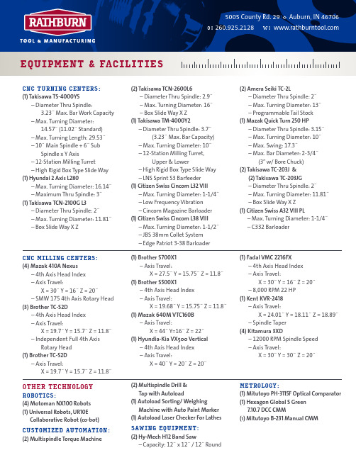
(1) Citizen Swiss Cincom L38 VIII – Max. Turning Diameter: 1-1/2˝ – JBS 38mm Collet System – Edge Patriot 3-38 Barloader
CNC MILLING CENTERS: (4) Mazak 410A Nexus
– 4th Axis Head Index – Axis Travel:
X = 30˝ Y = 16˝ Z = 20˝ – SMW 175 4th Axis Rotary Head (3) Brother TC-S2D – 4th Axis Head Index – Axis Travel:
X = 19.7˝ Y = 15.7˝ Z = 11.8˝ – Independent Full 4th Axis
Rotary Head (1) Brother TC-S2D
– Axis Travel: X = 19.7˝ Y = 15.7˝ Z = 11.8˝
OTHER TECHNOLOGY ROBOTICS: (4) Motoman NX100 Robots (1) Universal Robots, UR10E
(1) Autoload Laser Checker For Lathes
SAWING EQUIPMENT: (2) Hy-Mech H12 Band Saw
– Capacity: 12˝ x 12˝ / 12˝ Round
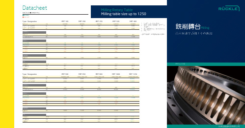
金圣通科技-德国RUCKLE(锐科乐)MRT≤1250铣削转台样本
8 10,500
20 6,500
40
7 13,500
10 10,000
20
6 15,500
˕ ˕ ˕
20,000
25,000
30,000 | ˕
+/- 2 0.02 0.01
+/- 2 0.025 0.01
+/- 2 | ˕ 0.03 | ˕ 0.01 | ˕
ሤࠉᙾѯMilling
ޣҴІЬ҂ԓђϏϜЗᔗң
ᚈᆨقಜ ᚈᆨװΩ
ᆡ࡚ २౫ᆡ࡚3 ᐘӪᘜ࡚ ༬ᘜ࡚ 4
mm kg kg
mm Nm
rpm Nm rpm Nm rpm
Nm
arcsec mm mm
Type / Designation
ᙾѯАω ॓ၸ२໕ |ޣఌᙾໆ ॓ၸ२໕ | Ь҂ఌᙾໆ 1
ኟᔣ၇ဋ ໆܜАω ഷτ་ఈ ᘜװΩ
HEADTec GmbH Otto-Schmerbach-Str. 19 D — 09117 Chemnitz Phone + 49 (0)371 — 334265 -0 Fax + 49 (0)371 — 334265 -98 info@headtec.de
Vario-Fertigungstechnik GmbH Tuchschererstr. 17 D — 09116 Chemnitz Phone + 49 (0)371 — 27828 -0 Fax + 49 (0)371 — 27828 -49 info@vario-ft.de
850
+/- 2 0.01 0.01
MRT 500
650|800|1,000 55,000 2,800
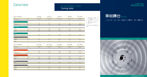
金圣通科技-德国RUCKLE(锐科乐)TRT车削转台样本
+|- 2 0.01 0.01
+|- 2 0.015 0.01
+|- 2 0.02 0.01
+|- 2 0.02 0.01
TRT
ᐘӪᘜ࡚ ༬ᘜ࡚
4
Type / Designation
ᙾѯАω ഷτϜЗ॓ၸ२໕ mm kg
TRT 1000
1,500 | 1,800 | 2,000 12,000
TRT 1400
ሰؒ
ࡋЙޠሰؒۢ؛ࠣޠѓ੬ ܓș Ꭱ ऌყޠ৵ѢምȄӤኻ๗ᄻАω ޠTRT ق ӗϏձѯȂє֥ΠөᆎϛӤޠᘩ८ІַڏȂ Ӊཏ೪ۢᙾഁ 10RPM ژ500RPMȂ ٯႁ ژ180kNm ାװΩȄାথܓѠڨܜђ ϏӈഷାѠႁ 5 ϵАȂ॓ၸΩ࣐ 200 ᏡȄ ᒶᐆܓᚈۢقಜւܼђϏࢻโװΩႁ 80kNm ਣȂᆱࡼۢڐ՞ᆡ࡚ܼ +/-5 ِऍȄଷ ԫϟѵȂΩᐈձַޠᆨћዻޠЍІᗘռ бܗտࠔݷᅏΤஞࡍԓ೪ॏȂጃߴႁژ ༬৸ 2500mmȂᐘӪᘜ࡚Ӷ 20͢mȂ༬৸ 500mmȂ༬ᘜ࡚Ӷ 5͢m ޠᆡྦ࡚Ȅ
Datasheet
Turning Rotary Table Turning table
Type / Designation
ᙾѯАω ഷτϜЗ॓ၸ२໕ mm kg
TRT 400
600 | 700 | 800 1,750
TRT 500
700 | 800 | 1,000 2,500
TRT 650
1,000 | 1,250 | 1,500 5,000
Distrito Industrial Alvorada / Viamao(DIAV)
锐普德数控R8010T车床数控系统用户手册

2H
172H
5.5 参数恢复..........................................................................................................................................13
0H
150H
1.1 产品特点............................................................................................................................................2
19H
169H
5.2 系统参数修改..................................................................................................................................12
20H
26H
176H
6.1 绝对坐标显示..................................................................................................................................15
27H
6H
156H
第四章 程序管理方式..................................................9
7H
157H
4 .1 程序管理...........................................................................................................................................9
六维台样本

32 kg
Rack 19″ ,3U 450×435×133 mm
以太网 230 V AC 50-60 Hz
轴坐标
范围
(1)
分辨精度
线行程 Tx
±75 mm
0.5 μm
线行程 Ty
±75 mm
0.5 μm
线行程 Tz
±50 mm
0.5 μm
角度轴 Rx
±15°
2.5 μrad
±20 mm
0.1 μm
线行程 Ty
±20 mm
0.1 μm
线行程 Tz
±10 mm
0.1 μm
角度轴 Rx
±10°
2 μrad
角度轴 Ry
±10°
2 μrad
角度轴 Rz
±15°
2 μrad
(1). 当其他轴在零位,以上平台中心为旋转点,此轴线角的最大值。 (2). 在每一个正负运动的方向,重复精度都会有正负 2 的误差。
AIRE 望远镜(印度)
六维台
有效负载 上平台尺寸 平台零位高度
重量 环境
控制
从垂直到水平负载达 到 500kg ø500 mm
~450 mm
90-120 kg 温度 -20℃ --40℃
湿度达 90%
控制盒尺寸 (W×D×H)
界面
需求电源
600×550×850 mm
以太网 120-240 V AC/8A
08
Sures
应用: 望远镜的定位 高精度定位 光学调整 无线测验 天线鉴定
技术参数 : 有效负载:500KG 分辨精度:0.1um 低交叉连轴运动 6DOF 低交叉耦合运动
SURES 是定位精度非常高的六维台。 它具备高刚性和高精度,专门设计 精密调节巨大望远镜的次镜。
CNC320立式数控转台设计说明书

机电工程学院毕业设计说明书设计题目: CNC320立式数控转台设计学生姓名:赵辉辉学号: 201215010621专业班级:机制Y1208指导教师:王宗才2016年 5 月28 日目录第1章引言 ----------------------------------------------------------------------------------- 11.1 设计要求----------------------------------------------------------------------------- 11.2设计思路----------------------------------------------------------------------------- 1 1.3设计准则 ------------------------------------------------------------------------------------------ 1第2章总体方案论证------------------------------------------ 32.1数控转台的布局 --------------------------------------------------------------------------------- 32.2驱动元件的选择 --------------------------------------------------------------------------------- 32.2.1 步进电动机 ---------------------------------------------------------------------------- 32.2.2伺服电动机 ---------------------------------------------------------------------------- 3 2.3传动方案的确定 --------------------------------------------------------------------------------- 4 2.4工作台的制动 ------------------------------------------------------------------------------------ 5 2.5工作台的定位 ------------------------------------------------------------------------------------ 7第3章数控转台的零件设计------------------------------------ 83.1伺服电动机的确定 ----------------------------------------------------------------------------- 83.2齿轮传动机构的设计-------------------------------------------------------------------------- 83.2.1齿轮的设计 --------------------------------------------------------------------------- 83.2.2齿轮机构的消隙 ----------------------------------------------------------------- 10 3.3蜗轮及蜗杆传动机构的设计 ------------------------------------------------------------- 103.3.1蜗轮及蜗杆的设计---------------------------------------------------------------- 103.3.2蜗轮蜗杆副机构的消隙 -------------------------------------------------------- 12 3.4蜗杆轴的计算与校核 ----------------------------------------------------------------------- 13 3.4.1轴的结构设计----------------------------------------------------------------------- 13 3.4.2轴的计算与校核-------------------------------------------------------------------- 13 3.5轴承的选用 ------------------------------------------------------------------------------------ 16 3.5.1轴承的类型 -------------------------------------------------------------------------- 163.5.2轴承的配合 -------------------------------------------------------------------------- 16 3.5.3 轴承的润滑 -------------------------------------------------------------------------- 163.5.4轴承的密封 -------------------------------------------------------------------------- 163.5.5 轴承的预紧 -------------------------------------------------------------------------- 16 3.6夹紧力的计算------------------------------------------------------------------------------- 16 第4章数控转台的控制系统设计------------------------------ 18 第5章数控转台的三维造型---------------------------------- 195.1蜗轮的三维造型---------------------------------------------------------------------------- 19 5.2 蜗杆的三维造型 ---------------------------------------------------------------------------- 215.3工作台的三维造型 ------------------------------------------------------------------------ 235.4 底座的三维造型 --------------------------------------------------------------------------- 245.5 底座与工作台的装配 --------------------------------------------------------------------- 245.6 夹紧瓦的三维造型------------------------------------------------------------------------ 24 结论-------------------------------------------------------- 27 设计总结 --------------------------------------------------------------------------------------- 28致谢---------------------------------------------------------------------------------------------- 29参考文献 -------------------------------------------------------------------------------------------------- 30摘要为了使一些特殊的零件能够在普通机床上加工出来,减少零件的加工费用,扩大机床的加工性能是非常有必要的。